STM32 ADC Conversion Time Explained
Uncover how to calculate and measure STM32 ADC conversion time. This tutorial Includes sampling, resolution, ADC clock formula, CubeMX setup, and logic analyzer demo.
Recommended Resources:
This is the 6th tutorial in the STM32 ADC series. In the previous tutorials we covered how to configure the ADC in STM32 F1, F4 and F7 series and how to use it in the single channel polling, interrupt and DMA modes to read the potentiometer data. We have also covered the Multiple channels in DMA Normal Mode, Circular Mode and Multiple Channels with DMA.
You Do not need to go through the previous tutorials in order to understand this one. But a basic knowledge of ADC configuration is needed.
VIDEO TUTORIAL
You can check the video to see the complete explanation and working of this project.
Check out the Video Below
Introducing STM32 ADC Peripheral
The Analog-to-Digital Converter (ADC) in STM32 microcontrollers is a powerful peripheral that allows the conversion of analog input signals into digital values. This capability enables STM32 devices to interface seamlessly with real-world sensors and analog inputs, such as temperature sensors, light sensors, potentiometers, and more. The ADC module is highly configurable and supports a range of resolutions and modes, making it suitable for both basic and advanced embedded applications.
Whether you’re developing a battery-powered IoT device or a high-speed data acquisition system, the STM32 ADC provides flexible configuration options, precision control, and efficient performance.
Here are some important features of STM32 ADC:
- Multi-Channel Support – Capable of reading from multiple analog inputs using internal channel scanning, reducing the need for external hardware.
- High Resolution Options – Offers selectable resolutions (6-, 8-, 10-, or 12-bit), allowing a balance between accuracy and conversion speed.
- Multiple Conversion Modes – Supports single, continuous, scan, and discontinuous modes to suit different application needs.
- Flexible Triggering – Conversion can be started via software or automatically triggered by hardware events like timers or external interrupts.
- Low Power Consumption – Designed with power-saving features, ideal for energy-efficient and battery-operated systems.
THE FORMULA
As per the ST’s documentation, the formula to calculate the total conversion time is shown below.
The above formula has 3 parameters:
- @Sampling Cycles is the time in terms of ADC CYCLES, taken by a particular channel to sample the data. This parameter is configurable in the cubeMX and it can be configured separately for each channel.
- @Conversion Cycles is the time in terms of ADC CYCLES, taken by the ADC to convert the sampled data. This parameter is not configurable, but it depends on the ADC resolution we set in the cubeMX. The Higher the resolution, the higher will be this parameter. This parameter also varies across different MCUs, but we can find the value in the reference manual of the MCU itself.
- @ADC Clock is the clock at which the ADC is running.
USING WITH STM32F103
The F103C8 MCU has 12 bit ADC resolution and it is not configurable. As per the reference manual, the conversion time for this 12 bit resolution is 12.5 Cycles.
As per the Formula, the sampling cycles and the ADC Clock is configurable in the cubeMX itself. Whereas the conversion cycles have a fixed value 12.5.
Let’s assume the ADC clock is 1MHz and the Sampling Time is configured as 239.5 Cycles. The Conversion Time has a fixed value of 12.5 Cycles. The total conversion time is calculated as shown below.
USING WITH STM32F446
The F446RE has configurable ADC resolution. The Conversion time with respect to the resolution is mentioned in the reference manual. Below is the image from pg-368 of the reference manual of F446RE.
Here, the Conversion Cycles depends on the resolution you select for the ADC
- For 12 bit Resolution, Conversion CYCLES = 12
- For 10 bit Resolution, Conversion CYCLES = 10
- For 8 bit Resolution, Conversion CYCLES = 8
- For 6 bit Resolution, Conversion CYCLES = 6
CubeMX Configuration
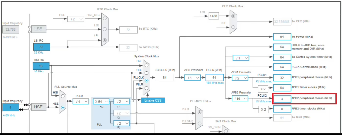
Below is the clock configuration for F446RE.
The APB2 peripheral clock is running at 4MHz. The ADC1, 2 and 3 all are connected to the APB2 Bus, therefore the ADC1 clock is also at the same frequency. We will use the prescaler to further reduce this clock.
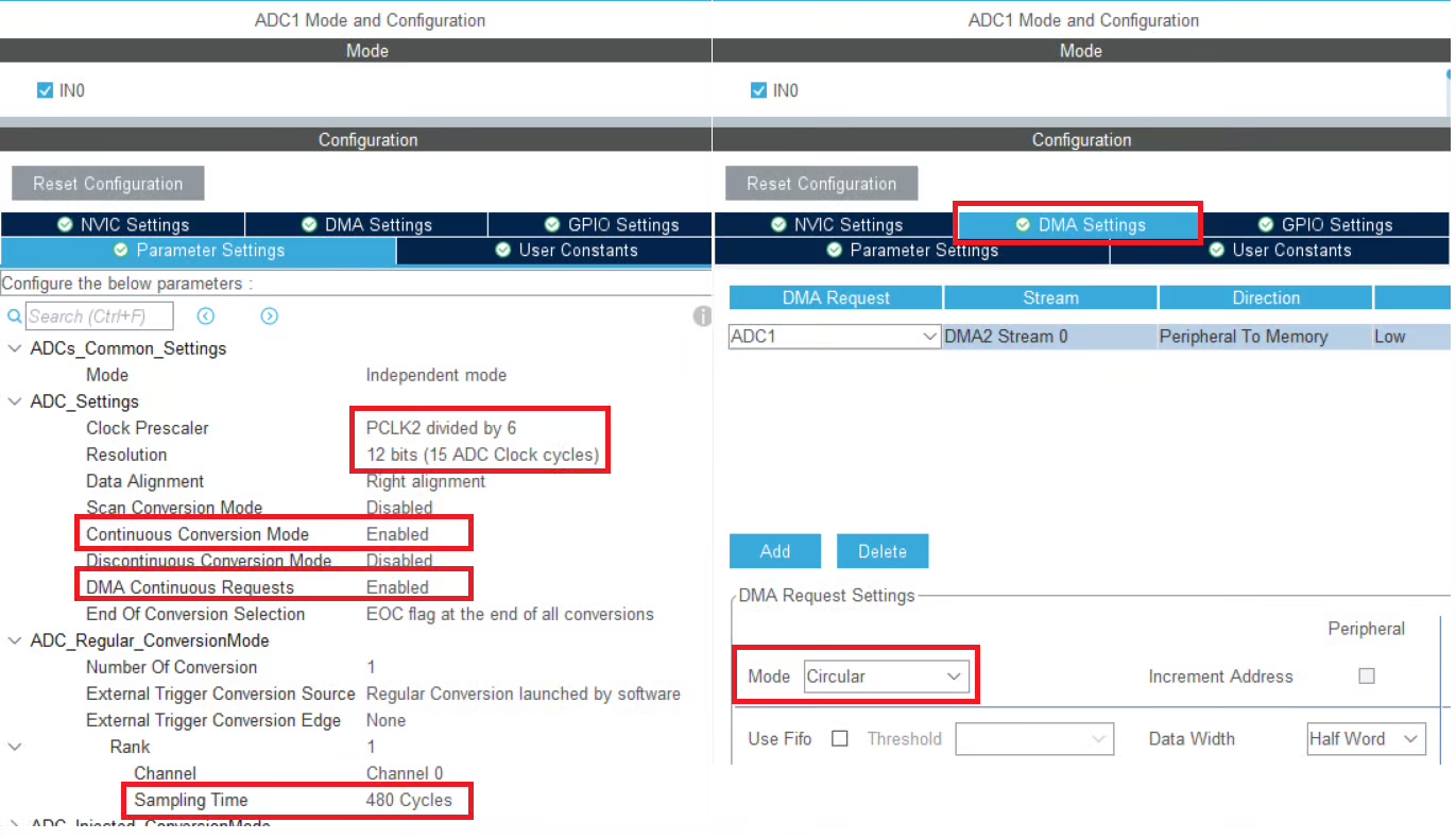
Below is the image showing the ADC configuration.
I am using the prescaler of 6 and this will bring the ADC clock down to 4000000/6 = 666.67 KHz. The ADC Resolution is set to 12bits, therefore the conversion cycles will be 12.
We will use the DMA to transfer the data from the ADC, therefore the DMA is enabled in circular mode. Along with DMA, the continuous conversion mode and DMA continuous request are also enabled.
The sampling time is set to 480 Cycles.
Below is the image showing the calculation for the Total Conversion Time.
We will use the pin PA1 to measure the conversion time for the ADC.
The pin PA1 is configured in the output mode. I will connect the pin PA1 to the logic analyzer, therefore the output speed of the pin is set to very high.
The Code
Inside the main function we will start the ADC in DMA mode.
uint16_t ADC_VAL;
int main()
{
  ...
  HAL_ADC_Start_DMA(&hadc1, &ADC_VAL, 1);
  while (1)
  {}
}ADC_VAL is the variable where the converted channel data will be stored and 1 is the number of channels we are converting.
Once the channel has been converted, an interrupt will trigger and the conversion complete callback will be called. Inside the callback we will toggle the pin PA1.
void HAL_ADC_ConvCpltCallback(ADC_HandleTypeDef *hadc)
{
HAL_GPIO_TogglePin(GPIOA, GPIO_PIN_1);
}The pin toggles each time the conversion is finished. Therefore the pin remains HIGH and LOW for same time, as taken by the ADC to finish the conversion. Hence the high or low time of the pin should be the same as the time we calculated using the formula.
Result
Below is the image showing the result in the logic analyzer.
As you can see above, the pin PA1 remained high for 738 microseconds. This is exactly the same conversion time that we calculated using the formula.
So our formula and calculation was precise, you can see that in the result.
USING WITH STM32H750VB
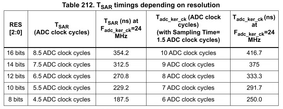
The H750 also has configurable ADC resolution. The Conversion time with respect to the resolution is mentioned in the reference manual. Below is the image from pg-952 of the reference manual of H750VB.
Here, the Conversion Cycles depends on the resolution you select for the ADC
- For 16 bit Resolution, Conversion CYCLES = 8.5
- For 14 bit Resolution, Conversion CYCLES = 7.5
- For 12 bit Resolution, Conversion CYCLES = 6.5
- and so on..
CubeMX Configuration
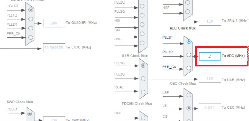
Below is the clock configuration for H750.
I have configured the ADC clock at 2 MHz. We will use the prescaler to reduce the clock further.
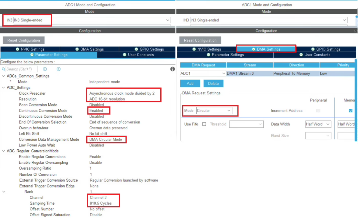
Below is the image showing the ADC configuration.
I am using the prescaler of 2 and this will bring the ADC clock down to 2000000/2 = 1MHz. The ADC Resolution is set to 16bits, therefore the conversion cycles will be 8.5.
We will use the DMA to transfer the data from the ADC, therefore the DMA is enabled in circular mode. Along with DMA, the continuous conversion mode should be enabled and conversion data management should be set to circular DMA.
The sampling time is set to 810.5 Cycles.
Below is the image showing the calculation for the Total Conversion Time.
We will use the pin PD8 to measure the conversion time for the ADC.
The pin PD8 is configured in the output mode. I will connect the pin PD8 to the logic analyzer, therefore the output speed of the pin is set to very high.
The Code
Inside the main function we will start the ADC in DMA mode.
uint16_t ADC_VAL;
int main()
{
  ...
  HAL_ADC_Start_DMA(&hadc1, &ADC_VAL, 1);
  while (1)
  {}
}
ADC_VAL is the variable where the converted channel data will be stored and 1 is the number of channels we are converting.
Once the channel has been converted, an interrupt will trigger and the conversion complete callback will be called. Inside the callback we will toggle the pin PD8.
void HAL_ADC_ConvCpltCallback(ADC_HandleTypeDef *hadc)
{
	HAL_GPIO_TogglePin(GPIOD, GPIO_PIN_8);
}The pin toggles each time the conversion is finished. Therefore the pin remains HIGH and LOW for same time, as taken by the ADC to finish the conversion. Hence the high or low time of the pin should be the same as the time we calculated using the formula.
Result
Below is the image showing the result in the logic analyzer.
As you can see above, the pin PD8 remained high for 1.638 milliseconds. This is not what we calculated using the formula. Actually this is twice the conversion time (819uS * 2) we calculated.
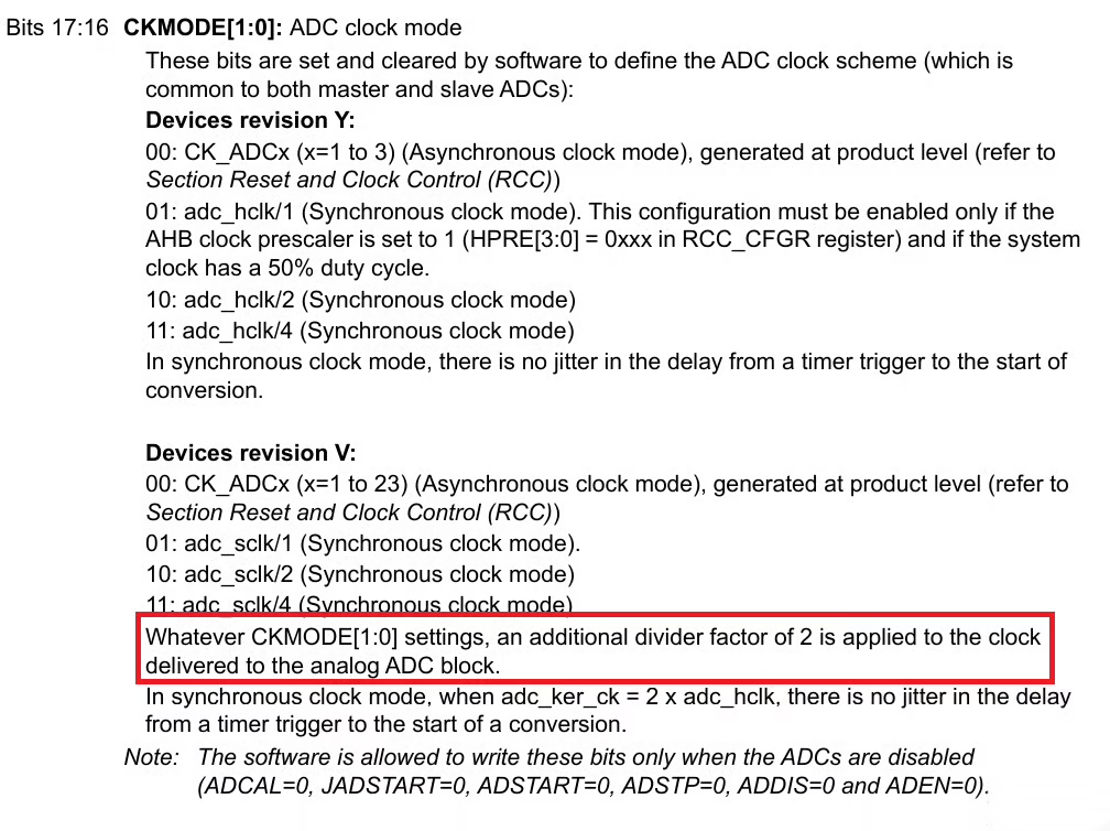
The reason for it is mentioned in the reference manual of H750VB. Below is the image from pg-1036 (ADC_CCR Register).
As mentioned in the manual, the devices with revision V always have an additional divide factor of 2 applied to the ADC Clock. Therefore the conversion time is twice the one which we calculated before.
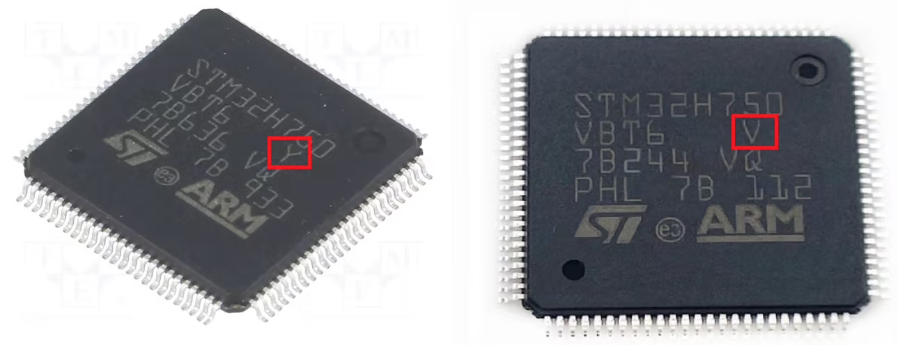
Below are the images showing different revisions for the same MCU.
So you have to carefully find out the device revision for the MCU you are using. If the MCU has revision V, the formula to calculate the total conversion time will be modified as shown below.









No code download for this video???