Home ▸ STM32 Tutorials ▸
Updated On: June 20, 2026
Interface SH1106 1.3″ OLED Display with STM32 Using I2C
The SH1106 looks almost identical to the 0.96″ SSD1306 — same four-pin I2C footprint, same 128×64 pixel layout — but its driver IC has 132 columns of internal memory instead of 128. That 2-pixel offset on each side catches most people out the first time they try to display something, and understanding it is the key difference between this tutorial and a generic OLED guide.
This tutorial shows you how to interface a 1.3″ SH1106 OLED display with an STM32F103 using I2C, STM32CubeMX, and HAL. You’ll configure I2C in Fast Mode (400 kHz), adapt the SH1106 driver library, handle the column offset correctly, and write code to show text, integers, floats, and bitmaps on screen. The complete CubeIDE project is available to download below.
Working with other OLED or LCD displays? Also check out the STM32 OLED tutorials collection — including the SSD1306 0.96″ I2C tutorial and the U8G2 graphics library port for STM32 — and the STM32 LCD tutorials for character LCD options.
SH1106 vs SSD1306 — Key Differences
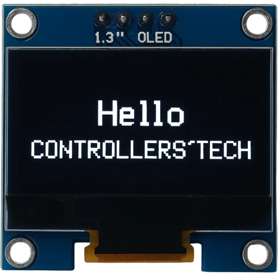
What Is the SH1106 OLED Display?
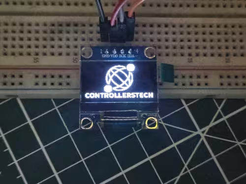
The SH1106 is a monochrome OLED driver IC used in 1.3-inch 128×64 pixel modules. Like the SSD1306, it communicates over I2C or SPI, runs without a backlight (each pixel is self-emissive), and delivers high contrast with very low current draw, making it a natural fit for battery-powered STM32 projects. The larger 1.3-inch panel gives it a slight edge over the 0.96-inch SSD1306 modules when readability matters.
Specifications at a Glance
| Feature | Specification |
|---|---|
| Display type | Monochrome OLED |
| Driver IC | SH1106 |
| Panel size | 1.3 inch |
| Visible resolution | 128 × 64 pixels |
| Internal IC memory | 132 × 64 pixels |
| Operating voltage | 3.3 V – 5 V (module-dependent) |
| Communication | I2C or SPI |
| Default I2C address | 0x3C or 0x3D |
| Viewing angle | > 160° |
| Backlight | None — self-emissive pixels |
The 132×64 Memory & 2px Column Offset Explained
This is the most important hardware detail for the SH1106. Its controller manages 132 columns internally, but the physical panel only shows 128 columns. The 128 visible columns are centred within the 132-column address space, leaving 2 invisible columns on each side.
In practice this means: if you want to draw at the leftmost visible pixel, you do not address column 0 — you address column 2. Most SH1106 drivers handle this automatically by adding a 2-pixel start offset in the SH1106_UpdateScreen() function. If your driver does not, or if you address the display directly with raw page/column commands, you must apply the offset manually.
This is also the root cause of the vertical white band some users see on the left edge of the display (see FAQ section). The SH1106_UpdateScreen fix in SH1106.c resolves it by writing:
SH1106_WRITECOMMAND(0xB0 + m);        // page address
SH1106_WRITECOMMAND(2 & 0x0F);        // lower column address = 2 (offset)
SH1106_WRITECOMMAND(0x10 | (2 >> 4)); // upper column address
SH1106_I2C_WriteMulti(SH1106_I2C_ADDR, 0x40,
                      &SH1106_Buffer[SH1106_WIDTH * m],
SH1106_WIDTH);Without this fix the display writes starting at column 0 of IC memory, which maps to 2 pixels off-screen, hence causing the blank band artifact on the left edge.
Wiring SH1106 OLED to STM32
The I2C wiring is identical to any other I2C OLED. We just need to connect four pins: power, ground, clock and data.
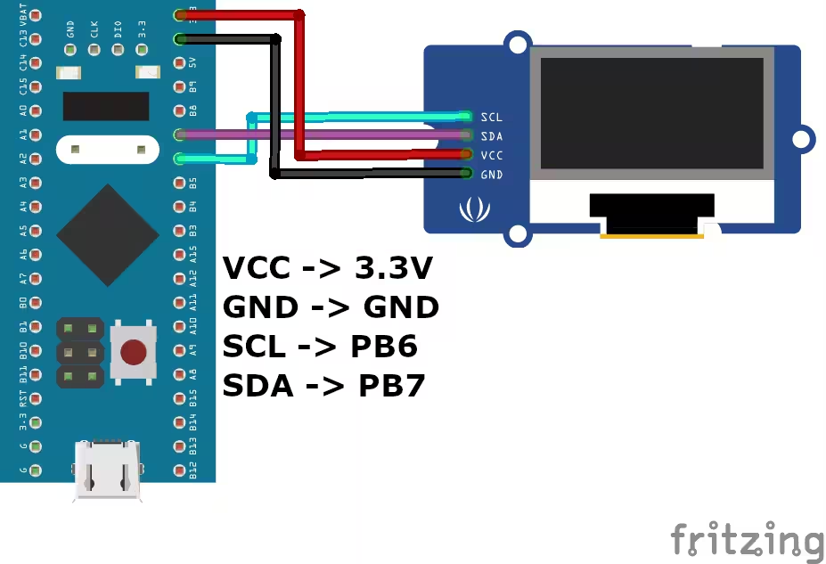
Connection Table & Voltage Notes
| OLED Pin | STM32F103 Pin | Description |
|---|---|---|
| VCC | 3.3 V | Power supply |
| GND | GND | Ground |
| SCL | PB6 | I²C clock |
| SDA | PB7 | I²C data |
Voltage notes:
Most 1.3-inch SH1106 modules accept 3.3 V – 5 V on VCC via an onboard regulator. STM32F103 I2C pins (PB6, PB7) are 5 V tolerant, but run at 3.3 V logic levels. Most modules include onboard pull-up resistors on SDA and SCL; add external 4.7 kΩ pull-ups only if your module does not.
CubeMX Setup, Driver Code & Results
Once the OLED is connected to the STM32 board, the next step is to configure the I2C peripheral using STM32CubeMX. We will start with the clock configuration.
Clock Configuration
Below is the image showing the Clock configuration for the project.
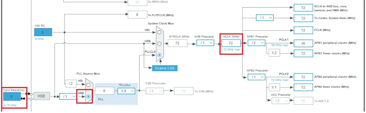
Clock the STM32F103 from the onboard 8 MHz external crystal. Enable the PLL multiplier to reach 72 MHz system clock. The I2C peripheral is sourced from APB1 — keep APB1 at or below 36 MHz in the clock tree.
I2C Configuration (Fast Mode, 400 kHz)
Below is the image showing the I2C configuration.
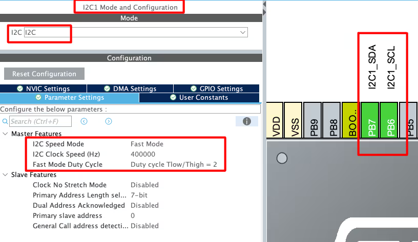
Enable I2C1 in CubeMX and configure:
- Mode: I2C
- Speed: Fast Mode — 400 kHz (required for the SH1106)
- Pins: PB6 (SCL) and PB7 (SDA) — auto-assigned
Note:
Standard Mode (100 kHz) may work but is not recommended. The SH1106 datasheet specifies Fast Mode for reliable data transfer, and slower speeds can cause display update artefacts.
Driver Setup — SH1106.c & SH1106.h
Copy SH1106.c, SH1106.h, fonts.c, and fonts.h from the downloaded project into the Src and Inc folders of your CubeIDE project.
Open SH1106.c and confirm the I2C handler:
extern I2C_HandleTypeDef hi2c1;
#define SH1106_I2C &hi2c1Change hi2c1 to match if you used I2C2 or I2C3 in CubeMX. Then check the resolution defines in SH1106.h:
#define SH1106_WIDTH  128
#define SH1106_HEIGHT  64
Important — apply the column offset fix:
In SH1106.c, locate the SH1106_UpdateScreen() function and ensure the page-write sequence uses column address 2 (not 0) as the starting column. See the code block in the offset section above. Without this fix, you will see a vertical blank band on the left side of the display.
Display Strings on the SH1106
#include "SH1106.h"
#include "fonts.h"
// inside main(), after MX_I2C1_Init()
SH1106_Init();
SH1106_GotoXY(10, 10);
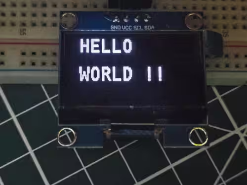
SH1106_Puts("HELLO", &Font_11x18, 1);
SH1106_GotoXY(10, 30);
SH1106_Puts("WORLD !!", &Font_11x18, 1);
SH1106_UpdateScreen();SH1106_Init() sends the full initialization command sequence. SH1106_GotoXY(x, y) positions the cursor in the framebuffer. SH1106_Puts() writes characters to the internal buffer. SH1106_UpdateScreen() must always be called to push the buffer to the physical display, nothing appears on screen until it runs.
Coordinate note:
Because of the 2-pixel column offset, SH1106_GotoXY(0, y) places content at the physical left edge of the screen — the driver handles the offset internally. Do not manually add 2 to your x coordinates unless you are writing raw page/column commands yourself.
Display Numbers and Floats
The SH1106 display only accepts ASCII character data. Convert numbers with sprintf before sending:
#include "SH1106.h"
#include "fonts.h"
#include "stdio.h"
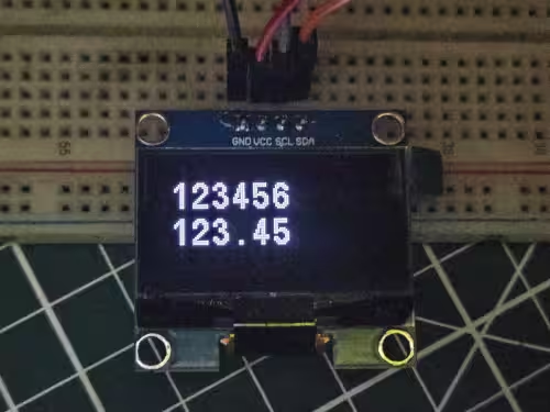
int num = 123456;
float flt = 123.45;
char bufnum[7];
char bufflt[7];
SH1106_Init();
sprintf(bufnum, "%d", num);
sprintf(bufflt, "%.2f", flt);
SH1106_GotoXY(10, 10);
SH1106_Puts(bufnum, &Font_11x18, 1);
SH1106_GotoXY(10, 30);
SH1106_Puts(bufflt, &Font_11x18, 1);
SH1106_UpdateScreen();Size buffers to hold the full string including sign, decimal point, fractional digits, and the null terminator. %d handles signed integers; %.2f formats floats to two decimal places.
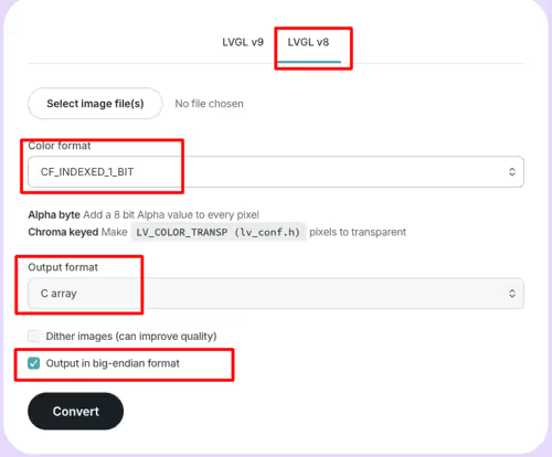
Display Bitmaps
The driver’s SH1106_DrawBitmap() function renders any monochrome image that has been converted to a C byte array.
Step 1 — Convert your image: Use the LVGL image converter tool. Set output format to Binary RGB332 and color depth to Indexed 1-bit, then download the C array. Copy the array into a bitmap.h header in your project.
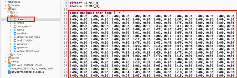
Step 2 — Draw and update:
#include "SH1106.h"
#include "bitmap.h"

SH1106_Init();
SH1106_DrawBitmap(0, 0, logo, 128, 64, 1);
SH1106_UpdateScreen();SH1106_DrawBitmap(x, y, bitmap, width, height, color) — origin (0, 0) is the top-left visible pixel. The 2-pixel column offset is applied internally by SH1106_UpdateScreen() when it flushes the buffer to the display, so bitmap coordinates map directly to visible screen positions.
STM32 SH1106 1.3″ OLED I2C — Video Tutorial
Watch the complete walkthrough: CubeMX Fast Mode I2C setup, SH1106 driver configuration, column offset handling, and HAL code examples for text, numbers, and bitmaps on a 1.3-inch 128×64 OLED with STM32F103.
FAQs — STM32 SH1106 OLED I2C
Conclusion
The SH1106's 2-pixel column offset is essentially the only wrinkle that separates it from a standard SSD1306 integration. Once the SH1106_UpdateScreen() function applies the correct column start address, everything else — text, numbers, bitmaps — follows the same framebuffer-then-flush pattern you'd use on any small OLED.
From here, the natural next steps depend on your project's needs. For a more capable graphics stack with built-in shape drawing, font rendering, and image display, the U8G2 library port for STM32 supports the SH1106 directly over both SPI and I2C. If you want to compare SH1106 against the 0.96-inch variant, the SSD1306 I2C tutorial covers the same flow with hardware scrolling added. For character-based output where a full graphics framebuffer is overkill, the I2C LCD1602 tutorial is the leaner alternative.
Download the complete CubeIDE project below — it includes SH1106.c/.h, fonts.c/.h, and the main.c examples for strings, numbers, and bitmaps, with the column offset fix already applied.
Download STM32 SH1106 1.3″ OLED I2C Project Files
Complete CubeIDE project including SH1106.c/.h driver (with column offset fix), fonts.c/.h, and main.c examples for strings, numbers, and bitmaps. Free to download — support the work if it helped you.
Browse More STM32 Oled Tutorials


Hi, thanks for the detailed explanation. Finally, I got my display working. But one problem I am facing is a vertical white band at the left side of the display. What could be the probable cause & how can I rectify it?
Hi, thanks for the detailed explanation. Finally, I got my display working. But one problem I am facing is a vertical white band at the left side of the display. What could be the probable cause & how can I rectify it?
I think the codes are not fully compatible with SH1106. So I make some changes.
Change the corresponding line in SH1106_UpdateScreen function in SH1106.c to this:
SH1106_WRITECOMMAND(0xB0 + m);
SH1106_WRITECOMMAND(2 & 0xf);
SH1106_WRITECOMMAND(0x10 | (2 >> 4));
SH1106_I2C_WriteMulti(SH1106_I2C_ADDR, 0x40, &SH1106_Buffer[SH1106_WIDTH * m], SH1106_WIDTH);
The changes is based on the solution as provided in this link. I post this the moment I got this to work, so there might be something else that I haven’t taken into account.