EEPROM and STM32
Well you all know what a EEPROM is and that’s why you are here. So let’s get straight to the point
In this tutorial we will interface an I2C based EEPROM with our beloved STM32. To be particular, I am using AT24C256, which is a 256Kb Serial EEPROM utilizing an I2C (2-wire) serial interface. Since we are using I2C, so the code remains same across all the STM32 Devices that supports I2C.
Also I will try to write a more generalized code, so that you can also use it for other EEPROMs that works on I2C.
VIDEO TUTORIAL
You can check the video to see the complete explanation and working of this project.
CubeMX Setup
There is noting special here. Just make sure you enable the I2C
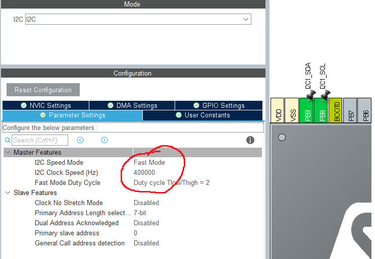
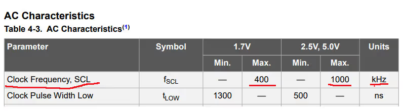
As you can see above, I have selected the fast mode for the I2C. The reason is that this EEPROM can support 400 KHz I2C clock speed and this is mentioned in the datasheet of the device.
This is it for the setup, Now let’s move to the code
The CODE
I have written a library for the EEPROM. You need to include the EEPROM.c and EEPROM.h files in the src and inc folders respectively. I will explain the functions as we progress in the tutorial
Everything important is in the EEPROM.c obviously, so we will take a look at this file
DEFINES
// Define the I2C
extern I2C_HandleTypeDef hi2c1;
#define EEPROM_I2C &hi2c1

// EEPROM ADDRESS (8bits)
#define EEPROM_ADDR 0xA0

// Define the Page Size and number of pages
#define PAGE_SIZE 64     // in Bytes
#define PAGE_NUM 512 // number of pages- As you can see above, first of all we need to define the I2C that we are using for the EEPROM (hi2c1 and &hi2c1)
- Next define thee address for the EEPROM. Make sure you use the 8 bit address (unlike Arduino, which uses 7 bits). These 8 bits include the R/W bit also
The address for the I2C device can be found in it’s datasheet
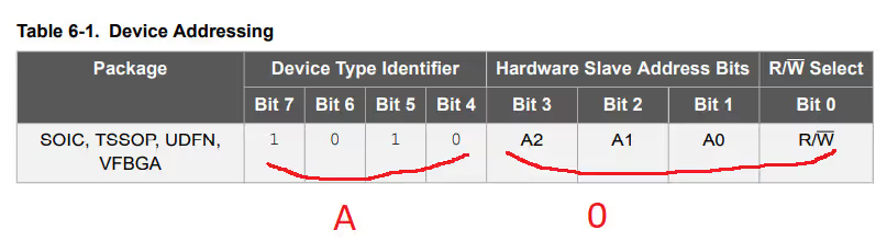
In the picture above, the address for AT24C256 is 0XA0. The A2, A1 and A0 pins can be modified physically to change the address of the device. This is useful in case if you have more than 1 EEPROM connected to the same I2C. The R/W bit can be kept 0 for write operation, and during Read, HAL functions makes it 1 on their own
- Now we need to define the PAGE size and the number of pages.
The memories are generally divided into pages. You need to fid the division for your memory type in it’s datasheet

In case of AT24C256, the memory is divided into 512 pages, and each page is 64 bytes, making it in total of 256 Kbit in size
EEPROM WRITE
Let’s write a function which can write the required data to the EEPROM.
void EEPROM_Write (uint16_t page, uint16_t offset, uint8_t *data, uint16_t size)This functions takes the following arguments
- @page is the number of the start page. Range from 0 to PAGE_NUM-1
- @offset is the start byte offset in the page. Range from 0 to PAGE_SIZE-1
- @data is the pointer to the data to write in bytes
- @size is the size of the data
Before we dig deep into the problems that we are going to face in this part and their solutions, let’s take a look at the address distribution for the memory
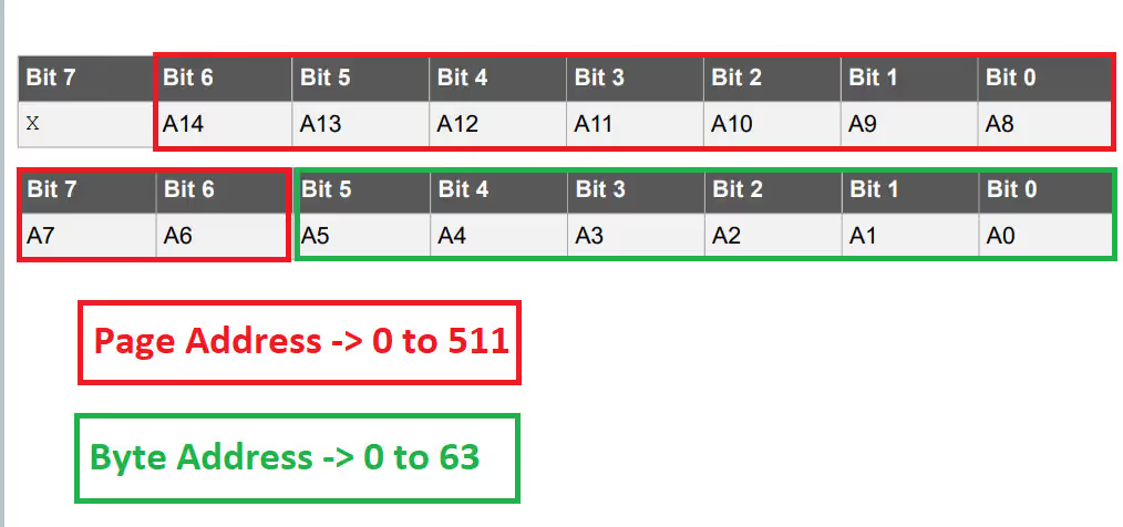
The problem that we face here is the way in which the data is written to the device. When we write the data in bulk, the Byte Address gets incremented by it’s own, but not the page address.
So we have to manually increment the page address. Let’s see the function now
void EEPROM_Write (uint16_t page, uint16_t offset, uint8_t *data, uint16_t size)
{

	// Find out the number of bit, where the page addressing starts
	int paddrposition = log(PAGE_SIZE)/log(2);

	// calculate the start page and the end page
	uint16_t startPage = page;
	uint16_t endPage = page + ((size+offset)/PAGE_SIZE);

	// number of pages to be written
	uint16_t numofpages = (endPage-startPage) + 1;
	uint16_t pos=0;

	// write the data
	for (int i=0; i<numofpages; i++)
	{
		/* calculate the address of the memory location
		 * Here we add the page address with the byte address
		 */
		uint16_t MemAddress = startPage<<paddrposition | offset;
		uint16_t bytesremaining = bytestowrite(size, offset);  // calculate the remaining bytes to be written

		HAL_I2C_Mem_Write(EEPROM_I2C, EEPROM_ADDR, MemAddress, 2, &data[pos], bytesremaining, 1000);  // write the data to the EEPROM

		startPage += 1;  // increment the page, so that a new page address can be selected for further write
		offset=0;   // since we will be writing to a new page, so offset will be 0
		size = size-bytesremaining;  // reduce the size of the bytes
		pos += bytesremaining;  // update the position for the data buffer

		HAL_Delay (5);  // Write cycle delay (5ms)
	}
}- Here we first find out the number of the bit, where the page address starts using log(PAGE_SIZE)/log(2). This bit will depend on your Page Size
- then we set the start page and the end page, and calculate the number of pages to be written
- Now inside the for loop, we will calculate the memory location
To do this we will shift the startpage by the page bit position ( 6, if the page size is 64 bytes) - For example, if the start page is 5, it will be shifted by 6 i.e 5<<6
- we will add the offset here to set the final memory location
- next calculate the remaining bytes
- now we will write the data to the EEPROM using HAL I2C MEM WRITE function
- we will update the parameters now
- and finally a 5 ms delay for the write cycle
This 5 ms is the time required for the EEPROM to write the data into the non volatile memory
This time is defined in the datasheet
EEPROM READ
EEPROM_READ is similar to write function. Every step is same here too.
void EEPROM_Read (uint16_t page, uint16_t offset, uint8_t *data, uint16_t size)
{
	int paddrposition = log(PAGE_SIZE)/log(2);

	uint16_t startPage = page;
	uint16_t endPage = page + ((size+offset)/PAGE_SIZE);

	uint16_t numofpages = (endPage-startPage) + 1;
	uint16_t pos=0;

	for (int i=0; i<numofpages; i++)
	{
		uint16_t MemAddress = startPage<<paddrposition | offset;
		uint16_t bytesremaining = bytestowrite(size, offset);
		HAL_I2C_Mem_Read(EEPROM_I2C, EEPROM_ADDR, MemAddress, 2, &data[pos], bytesremaining, 1000);
		startPage += 1;
		offset=0;
		size = size-bytesremaining;
		pos += bytesremaining;
	}
}As you can see above the entire function is same with very few changes
- Of course we will be reading data, so HAL I2C MEM READ function is used instead of write function
- And since no write cycle is used here, we don’t need to give the 5 ms delay
EEPROM PAGE ERASE
EEPROM_PageErase can be used to erase a single page in the memory
void EEPROM_PageErase (uint16_t page)
{
	// calculate the memory address based on the page number
	int paddrposition = log(PAGE_SIZE)/log(2);
	uint16_t MemAddress = page<<paddrposition;

	// create a buffer to store the reset values
	uint8_t data[PAGE_SIZE];
	memset(data,0xff,PAGE_SIZE);

	// write the data to the EEPROM
	HAL_I2C_Mem_Write(EEPROM_I2C, EEPROM_ADDR, MemAddress, 2, data, PAGE_SIZE, 1000);

	HAL_Delay (5);  // write cycle delay
}- Here we will also first calculate the memory location using the page
- then we create a buffer, where we store the data
- and write the data to the memory location
this write operation is limited to a single page, and that’s why the size will be the page size - since it’s a write cycle, we need to give a 5 ms seconds
- In case you want to erase the entire ROM, call this function in a for loop
Let’s write the main function now
The main function
uint8_t dataRead[128];

uint8_t dataWrite[100];

...........

int main(void)
{

  HAL_Init();

  SystemClock_Config();

  MX_GPIO_Init();
  MX_I2C1_Init();

  for (int i=0; i<512; i++)
  {
	  EEPROM_PageErase(i);
  }

  for (int i=0; i<100; i++)
  {
	  dataWrite[i] = i+10;
  }

  EEPROM_Write(3, 10, dataWrite, 100);
  EEPROM_Read(3, 0, dataRead, 128);

  while (1)
  {

  }
}- Here I am first erasing the entire EEPROM
- Then load the data into the write buffer. This data is just the ascii characters
- Now write the data to the EEPROM at the 3rd page with an offset of 10 bytes.
- And finally start reading from the beginning of the first page to see if the offset was set or not
you can see the result for this program below
Result
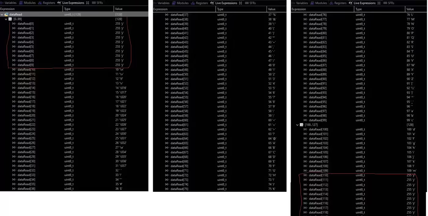
- You can see in the picture above that the first 10 bytes (0 to 9) are empty. This is because of the offset we set during the write process
- Then we have 100 bytes of data from the 10th Byte to 109th Byte
- After this, the ROM is again empty as there is no data written after 109th Byte


i have one doubt. While doing the READ operation, how the eeprom address remains same as WRITE operation address without change in the last bit of the address byte as ‘1’? I have not tried this code. But have this doubt before trying it.
It is taken care by the HAL_I2C functions we use,
HAL_I2C_Master_ReadorHAL_I2C_MemRead.We just need to provide the write address for the device. These functions will automatically add a 1 to the lsb when requesting the data from the slave device.
This code is great, it does work, but there are some issues with it. First, it only works on small EEPROMS (64K or less) that have 16 bit addressing. For larger devices that have 17 bit addressing, the MSB of the address is bit 1 of the device address. Second, the call to the log function is redundant, it does work but can take time on some devices, and cause large libraries to be included, increasing the code size. As the page size is known, you are better off to #define it instead, as it is only used in one place. And last but not least, the call to the HAL function does not check the return status. The call should be enclosed with an if((….) != HAL_OK), and the functions should be declared as returning a HAL_StatusTypeDef type, instead of void. Otherwise, good job!!
In my EEPROM.h I get an Unresolved inclusion for the #include “stm32f4xx_hal.h”.
I tried including the stm32f4xx_hal.h but then I have to keep adding more and more .h files.
Does anybody know if there is a way to include all .h file that are needed for the project ?
I saw somewhere else recently that apparently you should include the main “stm32f4xx.h” header instead of the more specific per device headers, as including those directly might break the header define hierarchy somehow. I’m not sure if this is the issue you had, but it fixed some missing declaration errors for me.
Hi guy, I was used the your code and many thanks. In my MCU (stm32f407VET6), writting and reading can’t be done at the time
// messgae = EEPROM_Erase();
// if (messgae != HAL_OK){
// printf(“erase error \r\n”);
// }
// messgae = EEPROM_Write(0, 0, font, 64);
// if (messgae != HAL_OK){
// printf(“write error \r\n”);
// }
// printf(“write\r\n”);
messgae = EEPROM_Read(1, 0, datar1, 23);
if (messgae != HAL_OK){
printf(“write error \r\n”);
}
for(u16 i=0;i<23;i++){
if(i%8 == 0 && i>0){
printf(“\r\n”); }
printf(“%02x “, datar1[i]);
}
printf(“\r\nread\r\n”);
}
Code works fine
Excellent tutorial.
To save code and memory, I have added a define instead of the LOG calculations:
#define PADDRPOSITION 5 // int PADDRPOSITION = log(PAGE_SIZE)/log(2);
Needs to be modified for each EEPROM type
Can you give me the datasheet of at24c256?
https://ww1.microchip.com/downloads/en/DeviceDoc/doc0670.pdf
It’s called google, same way you found this page actually, use it sometimes
Thank you for your awesome library!
i have integrated your library into my project with touchgfx on a stm32f469 disco. Unfortunately, the writing and reading of the eeprom doesn’t work, if I write in a float value of 123 and read it out again, I don’t get anything back, the read value remains at 0. Is that due to touchgfx or does something have to be configured differently here? I work in the CubeIDE.
It might be the pins. Make sure the I2C pins you are using are not used by touchGFX for some other things.
Try without TouchGFX first and see if it works, then go for touchGFX
For everyone who uses touchgfx and is looking for the error:
in main.c under / * USER CODE BEGIN I2C1_Init 2 * / the command HAL_I2C_DeInit (& hi2c1); is to declare, this is generated by touchgfx by default. After it has been declared, the eeprom works.
Thank you. save my time.
Thankyou so much
Fantastic work !!! many thanks !!!!!!!!