Updated On: April 30, 2026
STM32 UART Idle Line Detection: Interrupt & DMA Reception
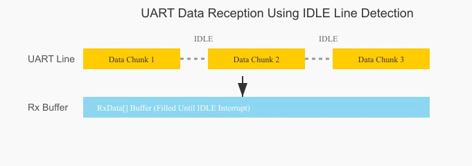
When receiving UART data of unknown length, the standard HAL_UART_Receive_IT() approach falls short — it requires you to specify an exact byte count up front, and stalls if the sender transmits fewer bytes than expected. The UART IDLE line detection feature solves this cleanly: the STM32 fires an interrupt automatically whenever the RX line goes idle after a transmission, regardless of how many bytes arrived.
This tutorial covers three progressively capable reception methods, all built on IDLE line detection. Interrupt mode handles small variable-length frames efficiently with minimal setup. DMA mode handles kilobyte-range data transfers without CPU involvement during reception. Chunked DMA mode handles arbitrarily large data — megabytes — by relaying received chunks to external storage as they arrive. All three use the same callback: HAL_UARTEx_RxEventCallback. The difference is only in how the buffer is managed.
This is Part 5 in the STM32 UART Series. You can check the other tutorials of this series below:
- Configure UART & Transmit Data
- Transmit using Interrupt & DMA
- Receive using Blocking & Interrupt
- Receive using DMA
- How to use Half Duplex Mode
- LIN Communication Tutorial
STM32 UART IDLE Line: How It Works
UART operates at a fixed baud rate, meaning there is a predictable timing between every bit and byte. As long as data keeps arriving within that timing window, the UART peripheral considers the line active. When the transmitter stops sending — leaving the line in the HIGH (mark) state for longer than a full character frame — the UART peripheral flags this as an IDLE condition.
This is useful precisely because it tells the receiver that a transmission has paused or ended, without requiring the sender to include a length header or a terminating character. The IDLE event fires after the last byte has been fully shifted in, giving the firmware a clean signal to process whatever arrived.
When the IDLE Interrupt Fires
Two common scenarios trigger it in practice:
- End of a complete message — the sender transmits a frame and stops. The IDLE interrupt fires once,
Sizereflects the total bytes received. - Chunked transmission — a large dataset is split into smaller packets with short pauses between them. Each pause long enough to exceed one character frame fires the IDLE interrupt separately.
Sizein each callback reflects the cumulative position in the circular DMA buffer, not just the bytes in that chunk.
Which Method to Use
| Scenario | Method | HAL Function |
|---|---|---|
| Variable-length frames, small data (< buffer size) | Interrupt | HAL_UARTEx_ReceiveToIdle_IT() |
| Large frames, a few kilobytes, known upper bound | DMA, single call | HAL_UARTEx_ReceiveToIdle_DMA() |
| Very large / continuous data, megabytes | DMA, circular + chunked copy | HAL_UARTEx_ReceiveToIdle_DMA() + memcpy |
The key difference between interrupt and DMA modes is not just data size — it’s CPU involvement. In interrupt mode the CPU handles every byte transfer from the peripheral. In DMA mode the DMA controller does the transfer and the CPU only wakes up when the buffer is full or an IDLE is detected.
STM32 UART IDLE Line: CubeMX Setup & Code
CubeMX Configuration
For interrupt mode:
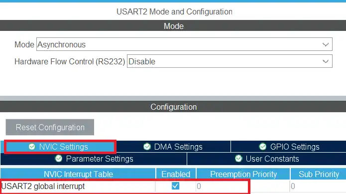
Let’s start by configuring the UART peripheral in the STM32 CubeMX. The image below shows the UART configuration in CubeMX.
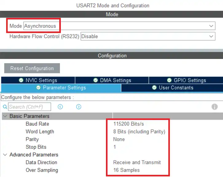
We will use the Asynchronous Mode for the communication. Only 2 pins are used in the Asynchronous mode, TX and RX. The baud rate is set to 115200. We need to use the same baud rate for the transmitter device also.
We shall enable the UART interrupt in the NVIC Settings as shown in the image below.
For DMA mode:
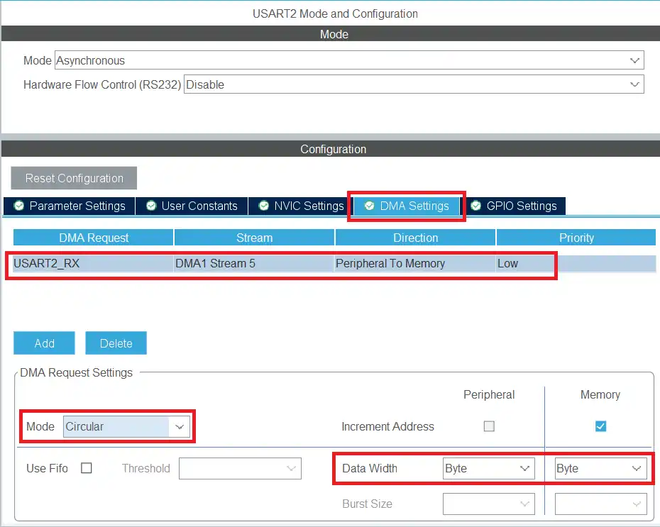
The image below shows the UART configuration in CubeMX.
We will use the Asynchronous Mode for the communication. Only 2 pins are used in the Asynchronous mode, TX and RX. The baud rate is set to 115200. We need to use the same baud rate for the transmitter device also.
We shall enable the UART_RX DMA in the DMA Settings as shown in the image below.
Note:
The DMA is configured in Circular mode, which is essential when working with large or continuous data streams. In circular mode, once the DMA reaches the end of the buffer, it automatically wraps around to the beginning and continues receiving data without stopping. This ensures that no data is lost, even if the incoming stream is longer than the buffer size or arrives continuously.
Method 1: Interrupt Mode (Small Data)
Use this when your maximum expected frame fits within a known buffer size — command parsers, RS485 frames, Modbus packets, GPS NMEA sentences.
Here we will call the function HAL_UARTEx_ReceiveToIdle_IT inside the main function. This function will enable the UART to receive the data in IDLE line interrupt mode.
uint8_t RxData[30];
uint16_t indx = 0;

int main(void)
{
    // ... HAL_Init, SystemClock_Config, MX_GPIO_Init, MX_USART2_UART_Init ...

    HAL_UARTEx_ReceiveToIdle_IT(&huart2, RxData, 30);

    while (1)
    {
        HAL_GPIO_TogglePin(GPIOA, GPIO_PIN_5);
        HAL_Delay(1000);
    }
}

void HAL_UARTEx_RxEventCallback(UART_HandleTypeDef *huart, uint16_t Size)
{
    indx = Size;  // Number of bytes received in this event

    // Process RxData[0..indx-1] here, or set a flag for the main loop

    // Re-arm: HAL disables the interrupt after each trigger
    HAL_UARTEx_ReceiveToIdle_IT(&huart2, RxData, 30);
}The RxData buffer is defined to store a maximum of 30 bytes of data. The indx variable will be used to store the size. In the main function we will call the function HAL_UARTEx_ReceiveToIdle_IT to receive 30 bytes of data in the interrupt mode.
When 30 bytes of data is received or an IDLE Line is detected before that, an interrupt will trigger and the HAL_UARTEx_RxEventCallback will be called. We can process the received data in this callback.
The @Size parameter of this callback represents how many data bytes has been received when the interrupt is triggered. We will store the size to the indx variable so that it can be later used in the while loop or any other function.
The interrupt is disabled after it gets triggered, so we need to call the interrupt again at the end of the callback. This is to make sure that the data reception is continuous.
Result:
The following output demonstrates how the UART IDLE line interrupt works in STM32. These images show the transmitted data from the serial monitor and how the microcontroller receives and processes it using the IDLE line detection feature.
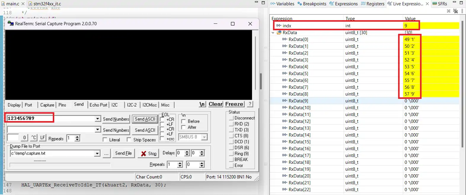
In the first image, you can see 9 data bytes being sent from the serial monitor. The second part of the output displays how these bytes are stored in the RxData buffer, along with the current value of the indx variable. This confirms that the IDLE line interrupt correctly detects the end of transmission and processes the data.
This interrupt-based method works well for receiving small packets of data when the exact size is unknown. As long as the data size is less than or equal to the buffer length, the reception will be reliable.
Method 2: DMA Mode — Kilobyte-Range Data
Use this when receiving a single large frame (firmware chunk, file transfer, bulk sensor data) that fits entirely in RAM.
Here we will call the function HAL_UARTEx_ReceiveToIdle_DMA just once. Below is the code for the same.
uint8_t RxData[4096];
uint16_t indx = 0;
int count = 0;

int main(void)
{
    // ... init ...

    HAL_UARTEx_ReceiveToIdle_DMA(&huart2, RxData, 4096);

    while (1)
    {
        HAL_GPIO_TogglePin(GPIOA, GPIO_PIN_5);
        HAL_Delay(1000);
    }
}

void HAL_UARTEx_RxEventCallback(UART_HandleTypeDef *huart, uint16_t Size)
{
    indx = Size;   // Cumulative position in the circular DMA buffer
    count++;       // How many IDLE events fired (equals number of chunks from sender)
}The RxData buffer is defined to store a maximum of 4096 bytes of data. The indx variable will be used to store the size. The count variable tracks how many times the callback was called. In the main function we will call the function HAL_UARTEx_ReceiveToIdle_DMA to receive 4096 bytes of data in the DMA mode.
When 4096 bytes of data is received or an IDLE Line is detected before that, an interrupt will trigger and the HAL_UARTEx_RxEventCallback is called. We can process the received data in the callback.
The @Size parameter of this callback represents how many data bytes has been received when the interrupt is triggered. We will store the size to the indx variable so that it can be later used in the while loop or any other function. We will also increment the count variable to track how many times this callback was called.
Result:
The image below demonstrate the output when receiving data using the UART IDLE line detection with DMA in circular mode on an STM32 microcontroller. They show how the MCU handles large data streams efficiently without losing any bytes.
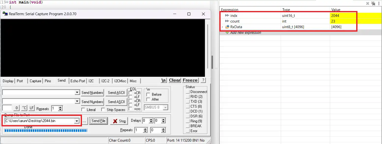
In the example above, the microcontroller successfully receives the entire dataset. The indx variable reflects the total size of the transmitted data, confirming that all bytes were captured correctly.
When transmitting large datasets, the sender often divides the data into smaller chunks (23 bytes per chunk in this example). Each pause between chunks triggers the IDLE line interrupt multiple times. With DMA in circular mode, new data is written sequentially into the buffer, and the Size variable retains its value across multiple calls. This cumulative approach ensures that the indx variable represents the total data received, not just the bytes from the most recent interrupt.
The count variable indicates how many times the interrupt callback was triggered during the transfer, providing insight into the chunking behavior of the sender.
This DMA-based method is ideal for receiving data in the range of a few kilobytes, as the buffer can store all incoming bytes in RAM. The received data can then be processed either immediately within the callback or later in the main loop. The indx variable serves as a reliable measure of the total data received.
Method 3: DMA Mode — Large / Chunked Data
Use this when data exceeds available RAM — receiving megabyte-scale files, streaming sensor data to SD card, or any case where the total size is unknown at compile time.
When handling very large amounts of data, often in the range of megabytes, a simple UART reception approach may fail. This happens because defining a buffer large enough to hold all the data in RAM is impractical. To overcome this, we use a smaller buffer to receive data in chunks. Each chunk is then transferred to an external memory storage, such as an SD card or external flash memory.
The following code demonstrates this approach using STM32 HAL functions.
#define RXSIZE 256

uint8_t  RxData[RXSIZE];       // Circular DMA receive buffer
uint8_t  FinalBuf[4096];       // Destination — replace with SD card write in production
uint16_t indx1 = 0;            // Read position in RxData
uint16_t indx2 = 0;            // Write position in FinalBuf
uint16_t rxcplt = 0;           // Number of complete RXSIZE chunks received
int      count  = 0;           // Total callback invocations

int main(void)
{
    // ... init ...

    HAL_UARTEx_ReceiveToIdle_DMA(&huart2, RxData, RXSIZE);

    while (1)
    {
        HAL_GPIO_TogglePin(GPIOA, GPIO_PIN_5);
        HAL_Delay(1000);
    }
}

void HAL_UARTEx_RxEventCallback(UART_HandleTypeDef *huart, uint16_t Size)
{
    count++;
    memcpy(FinalBuf + indx2, RxData + indx1, Size - indx1);

    if (Size == RXSIZE)
    {
        // Full buffer received — DMA has wrapped, reset read pointer
        rxcplt++;
        indx2 = RXSIZE * rxcplt;
        indx1 = 0;
    }
    else
    {
        // Partial buffer (IDLE fired before buffer full)
        indx2 += (Size - indx1);
        indx1 = Size;
    }
}Here, RxData is a 256-byte buffer used for chunked reception, while FinalBuf represents the complete data storage in an external memory device. The indx1 variable keeps track of the current position in RxData, and indx2 tracks the position in FinalBuf.
The rxcplt variable counts how many 256-byte chunks have been received, which helps update indx1 and indx2 correctly. Finally, count tracks the number of times the RX callback is triggered.
In the main function, we call HAL_UARTEx_ReceiveToIdle_DMA to start receiving data in DMA mode. This function enables the UART peripheral to receive data until the buffer is full or an IDLE line is detected.
int main()
{
  ....
  HAL_UARTEx_ReceiveToIdle_DMA(&huart2, RxData, RXSIZE);
  while (1)
  {
    HAL_GPIO_TogglePin(GPIOA, GPIO_PIN_5);
    HAL_Delay(1000);
  }
}When 256 bytes are received or an IDLE line is detected before that, an interrupt triggers the RX event callback. This is where the received data is processed and stored in the FinalBuf buffer.
void HAL_UARTEx_RxEventCallback(UART_HandleTypeDef *huart, uint16_t Size)
{
	memcpy (FinalBuf+indx2, RxData+indx1, Size);
	if (Size == RXSIZE)
	{
		rxcplt++;
		indx2 = RXSIZE*rxcplt;
		indx1=0;
	}
	else
	{
		indx2 = indx2 + (Size-indx1);
		indx1 = Size;
	}
}In the callback function:
- The
memcpyfunction copies the received data from RxData to FinalBuf. - If a full 256-byte chunk is received, rxcplt is incremented, and indx2 and indx1 are updated accordingly.
- If less than 256 bytes are received, indx2 is incremented by the actual number of bytes received, and indx1 is updated to the new position in RxData.
This approach ensures large data can be reliably received in small chunks without exhausting the MCU’s RAM.
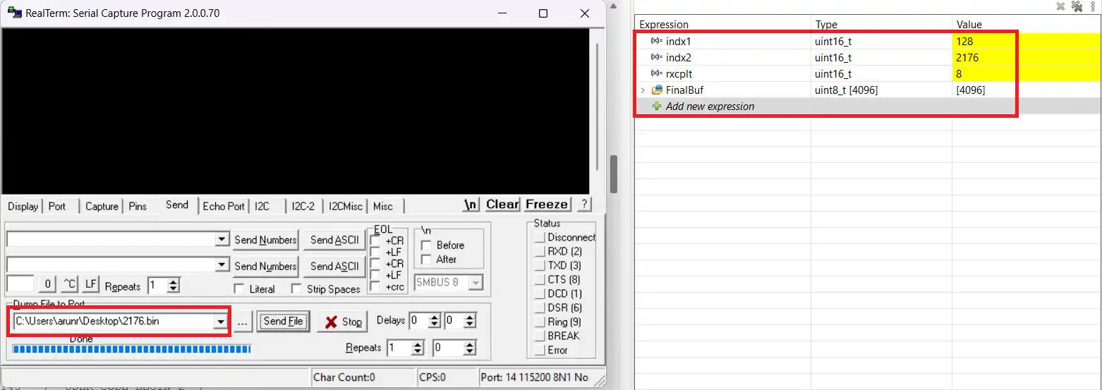
As you can see above, the indx2 variable is the same as the size of the file sent by the software. The rxcplt is 8, which represents how many times the entire 256 bytes were received. The indx1 variable represents the number of bytes received after last time the 256 bytes were received. 256*8 + 128 = 2176.
STM32 UART IDLE Line Reception — Video Tutorial
This video walks through all three IDLE line reception methods on STM32 — interrupt mode for small variable-length frames, DMA mode for kilobyte-range data, and chunked DMA mode for large continuous streams. Includes CubeMX configuration, live code walkthrough, and verified results for each method.
STM32 UART IDLE Line — Frequently Asked Questions
Conclusion
In this tutorial, you learned three ways to receive variable-length UART data on STM32 using IDLE line detection — interrupt mode for small frames, single DMA call for kilobyte-range data, and circular DMA with chunked memcpy for large continuous streams.
The key things to carry forward: always re-arm in interrupt mode, never re-arm in DMA Circular mode, understand that Size in DMA mode is a cumulative buffer position not a per-callback byte count, and keep callback processing short to avoid blocking in interrupt context.
This is the reception method used in the RS485 tutorial and the Modbus RTU series — both rely on HAL_UARTEx_ReceiveToIdle_IT() as their frame detection mechanism. In the next part of the UART series, we cover Half-Duplex communication using single-wire UART mode.
Download STM32 UART IDLE Line Project Files
Complete CubeIDE project with all three IDLE line reception methods — interrupt mode, DMA for kilobyte-range data, and chunked DMA for large data streams. Includes CubeMX config and HAL source for UART2. Free to download — support the work if it helped you.
Browse More STM32 UART Tutorials
STM32 UART Part 2 – Transmit using DMA & Interrupt
STM32 UART Part 3 – Receive Data in Blocking & Interrupt mode
STM32 UART DMA Receive: Normal & Circular Mode (HAL)
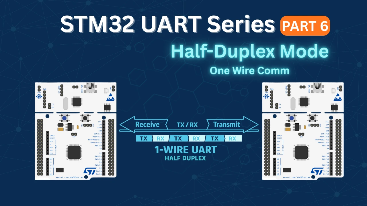
STM32 UART Part 6 – Half-Duplex Communication (Single-Wire Mode)
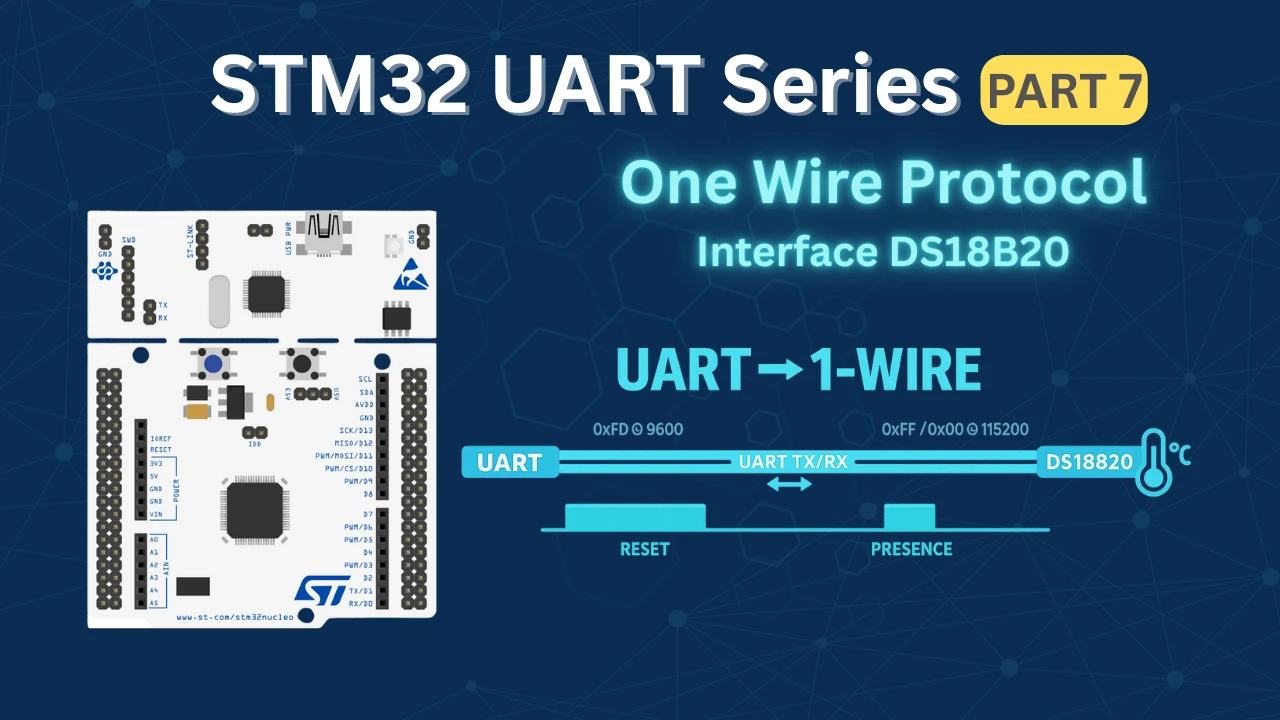
STM32 UART Part 7 – How to use one-Wire Protocol

Subscribe
Login
0 Comments
Newest
