Home ▸ STM32 Tutorials ▸
Updated On: March 23, 2026
Send and Retrieve Data from Display
This is the 4th tutorial in the STM32 LVGL series and today we will see how to send and retrieve data from the display. In today’s tutorial, we will send the data from UART and ADC to the display. Also we will retrieve the button states from the display and control the LEDs on the MCU.
VIDEO TUTORIAL
You can check the video to see the complete explanation and working of this project.
Connection & CubeMX Config
I have already covered in the previous tutorial how to connect the SPI Display and the touch controller to the MCU. I am skipping that part and will only focus on the UART, ADC and LEDs in today’s tutorial.
UART Config
Below shown is the UART configuration in the cubeMX.
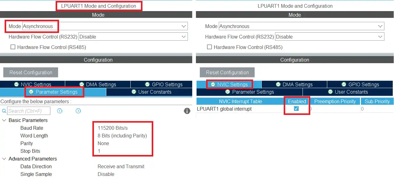
The UART is enabled in the Asynchronous mode with 115200 Baud, 8 data bits, 1 stop bit and no parity. I have also enable the UART interrupt to receive the data in the Interrupt Mode.
below is the image showing the connection to the USB TTL Module.
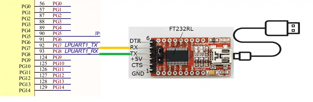
The UART pins are always connected in cross, connecting the TX pin to the RX of the module and RX pin to the TX of the module. The module is then connected to the computer, where we will receive the data from.
ADC
The ADC will be used to read the Potentiometer voltage in the digital form. We will then display the digital values on the UI.
Below is the image showing the ADC configuration in the cubeMX.
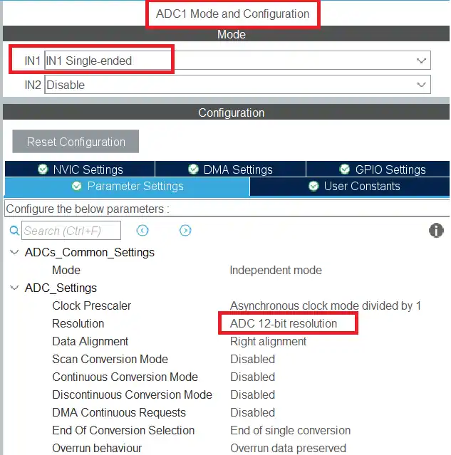
I have enabled the ADC channel 1 in the single ended mode. The resolution is set to 12 bits.
The image below shows the Potentiometer connection to the MCU.
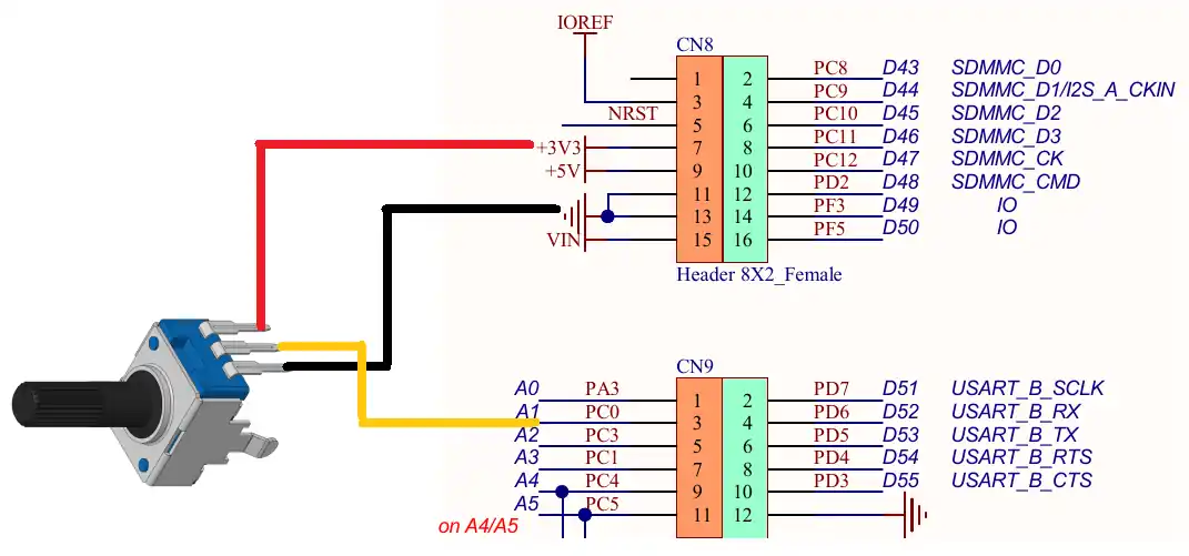
The potentiometer is powered by the 3.3V from the MCU itself. The analog pin is connected to the pin PC0, which is the ADC1 CH1 pin.
LEDs
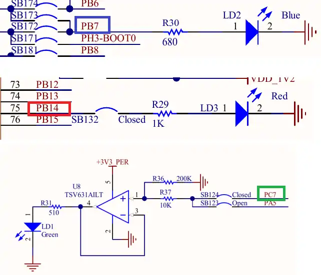
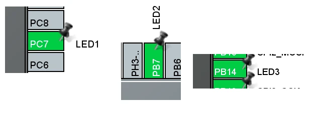
I am using 3 on board LEDs, which will be controlled by the buttons on the display. Below the image shows the LEDs and their pins.
In the cubeMX, we will set these pins as output as shown below.
UI Design
I have designed a text area to display the UART data.
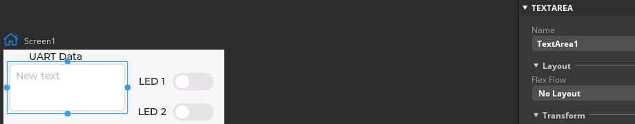
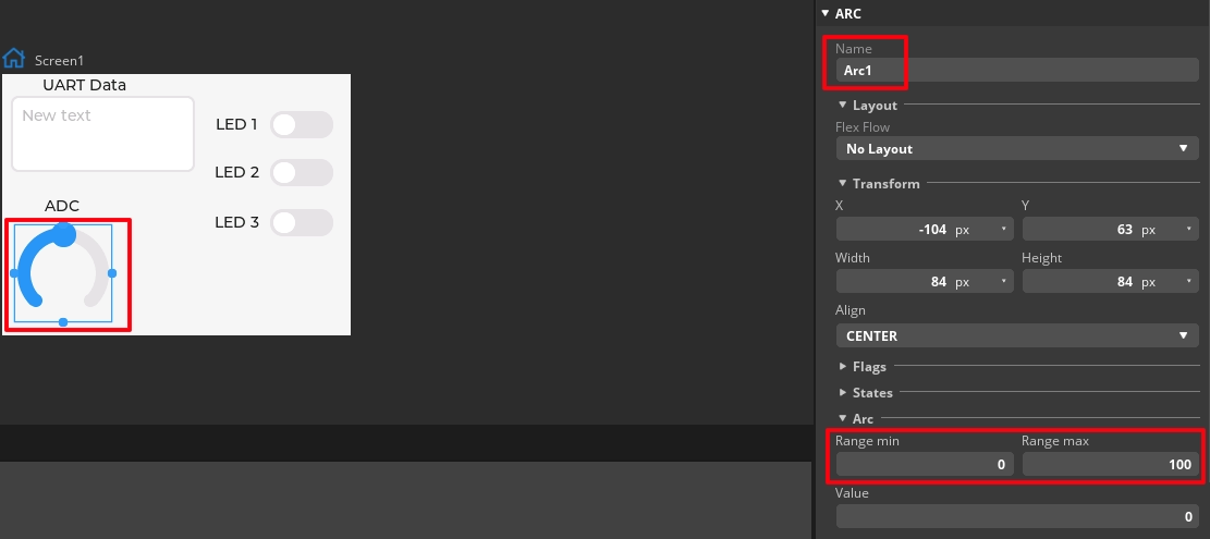
The Arc will be used to display the ADC value. The arc range is set between 0 to 100, so we will also map our ADC value within this range.
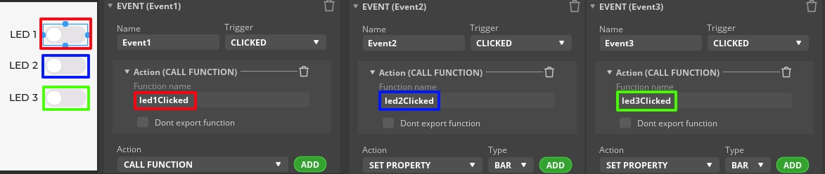
There are 3 switches to control the 3 LEDs on the MCU. I have defined events for all the 3 switches, which will trigger when the switch is clicked. Here we will call respective function for each switch.
The Code
ADC function
We will write a separate function to Read ADC and send it to the UI.
void adcRead (void)
{
	HAL_ADC_Start(&hadc1);
	HAL_ADC_PollForConversion(&hadc1, 100);
	uint16_t ADC_VAL = HAL_ADC_GetValue(&hadc1);
	HAL_ADC_Stop(&hadc1);

	int value = map (ADC_VAL, 0, 4095, 0, 100);
	lv_arc_set_value(ui_Arc1, value);
}Here we will Read the ADC value in the polling mode. Then map the value within the range of 0 to 100. And finally send it to the Arc we created in the UI.
We will call the ADC function in the while loop inside the main function.
  while (1)
  {
	  lv_timer_handler();
	  HAL_Delay(5);

	  adcRead();
}UART Function
Inside the main function, we will receive the data via the UART in the interrupt mode.
HAL_UARTEx_ReceiveToIdle_IT(&hlpuart1, RxData, 32);Here I am receiving 32 bytes at max. Once all the 32 bytes has been received, or if there is an IDLE line before that, an interrupt will trigger and the RXEventCallback will be called.
void HAL_UARTEx_RxEventCallback(UART_HandleTypeDef *huart, uint16_t Size)
{
	lv_textarea_set_text(ui_TextArea1, RxData);
	memset (RxData, '\0', 32);
	HAL_UARTEx_ReceiveToIdle_IT(&hlpuart1, RxData, 32);
}Inside the callback, we will send the Received data to the textArea in the UI. Then clear the buffer to remove the residue and call the receive function again.
Button Events
We have defined 3 buttons on the UI. When the buttons will be clicked, the UI events call the respective functions.
void led1Clicked(lv_event_t * e)
{
	if (lv_obj_has_state(ui_Switch1, LV_STATE_CHECKED))
	{
		HAL_GPIO_WritePin(LED1_GPIO_Port, LED1_Pin, GPIO_PIN_SET);
	}

	else
	{
		HAL_GPIO_WritePin(LED1_GPIO_Port, LED1_Pin, GPIO_PIN_RESET);
	}
}Here I have shown the function for LED1 button only. The rest of them are also the same.
Basically we will check the state of the switch. If the switch is checked (if it is ON), we will turn the respective LED ON. Otherwise turn the LED OFF.
The Result
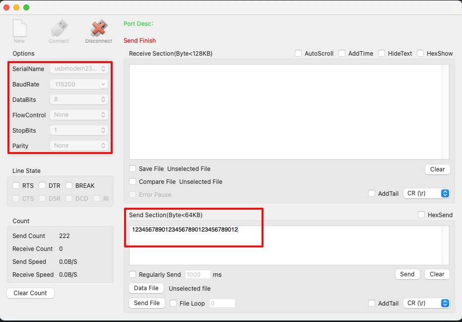
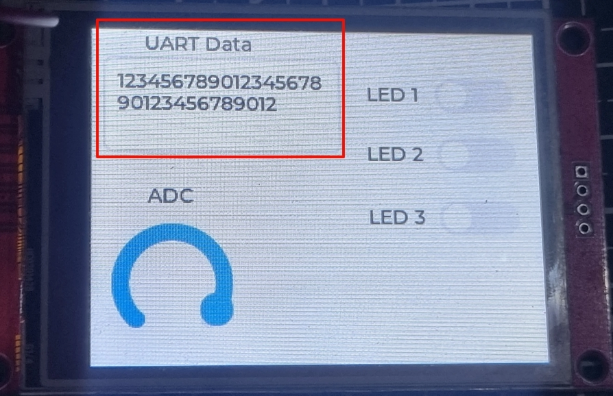
Below the images shows the UART Data sent by the computer and the one displayed on the LCD.
To view the Buttons and ADC output, check out the video below.
STM32 LVGL Tutorial Series
LVGL on STM32 || PART 2
LVGL on Riverdi STM32-H7 Display
LVGL ON STM32 || PART5
LVGL on STM32 || PART 6
LVGL on STM32 || PART7 || Load LVGL from Ext Flash
STM32 GC9A01 Round Display: SPI & LVGL Integration Guide
STM32 Analog Clock on GC9A01 — LVGL, SquareLine Studio & RTC

Subscribe
Login
0 Comments
Newest
