
Updated On: June 20, 2026
Getting Started with TouchGFX and STM32: Step-by-Step Guide
In this TouchGFX STM32 tutorial, you will learn how to get started with GUI development on STM32 Discovery boards, including STM32F7 and STM32H7 families. TouchGFX is a powerful and beginner-friendly GUI design tool from ST, making it very convenient to build modern user interfaces for STM32 microcontrollers.
In this project, we will create a simple embedded GUI where a TouchGFX toggle button on the display controls an LED connected to the microcontroller. Step by step, you will see how to set up a project in TouchGFX Designer, add widgets, generate code, and integrate everything in STM32CubeIDE.
This is Part 1 of the STM32 TouchGFX tutorial series, and it covers the basics. You will design a button-based GUI in TouchGFX, configure hardware in CubeMX, and write the code in CubeIDE to link the two. By the end, you will understand the foundation of interactive GUI design on STM32, which you can expand in advanced parts of this series.
For upcoming topics, the series will also explore other TouchGFX components and show how to use them effectively with STM32 MCUs.
STM32 TouchGFX Video Tutorial
Prefer video? Watch the same TouchGFX configuration, CubeMX setup, and code in action.
Watch the Video
Table Of Contents
- Benefits of Using TouchGFX for STM32 GUI Development
- STM32 TouchGFX Project Prerequisites
- Step 1: Create Project in TouchGFX Designer
- Step 2: Build the GUI – Add Background and Toggle Button
- Step 3: Define Interaction in TouchGFX Designer
- Step 4: Generate Code & Open in STM32CubeIDE
- Step 5: Configure Hardware with STM32CubeMX
- Step 6: Write the ToggleLED() Function in Code
- Step 7: Build, Flash & Test
- Step 8: Results & Verification
- Conclusion
Benefits of Using TouchGFX for STM32 GUI Development
Before we start building the project, it’s important to understand why developers prefer TouchGFX with STM32 microcontrollers. TouchGFX is a powerful embedded GUI framework designed specifically for STM32 boards, and it offers several advantages that make GUI development easier and faster.
Key Benefits of TouchGFX on STM32:
- Optimized for STM32 hardware – It takes full advantage of STM32’s graphics accelerators and memory features, which results in smooth performance.
- Beginner-friendly interface – The drag-and-drop designer allows even beginners to create professional-looking GUIs without deep coding knowledge.
- Low resource usage – TouchGFX is lightweight, so you can run rich graphics on microcontrollers with limited RAM and Flash.
- Wide library of widgets – It comes with ready-to-use buttons, images, text areas, and animations that save development time.
- Seamless STM32CubeIDE integration – It works directly with STM32CubeIDE and STM32CubeMX, making it easy to connect GUI elements with hardware.
- Real-world applications – TouchGFX is used in IoT devices, home appliances, medical displays, and industrial systems where interactive graphics are required.
By using TouchGFX for STM32 GUI projects, you get a professional toolchain that simplifies embedded graphics development while delivering excellent performance on microcontrollers.
STM32 TouchGFX Project Prerequisites
Before starting this TouchGFX STM32 tutorial, make sure you have the required hardware and software ready. The project uses the STM32F750 Discovery board with its built-in display, along with tools like TouchGFX Designer, STM32CubeMX, and STM32CubeIDE.
Here are the components used in this project. Some links are affiliate links that help support this work at no extra cost to you:
- STM32 TouchGFX Designer
- STM32 CubeIDE
- STM32 Discovery board with TouchGFX Support
Step 1: Create Project in TouchGFX Designer
The first step in building your STM32 GUI project is creating a new project in TouchGFX Designer. The image below shows how to create a project in TouchGFX Designer.
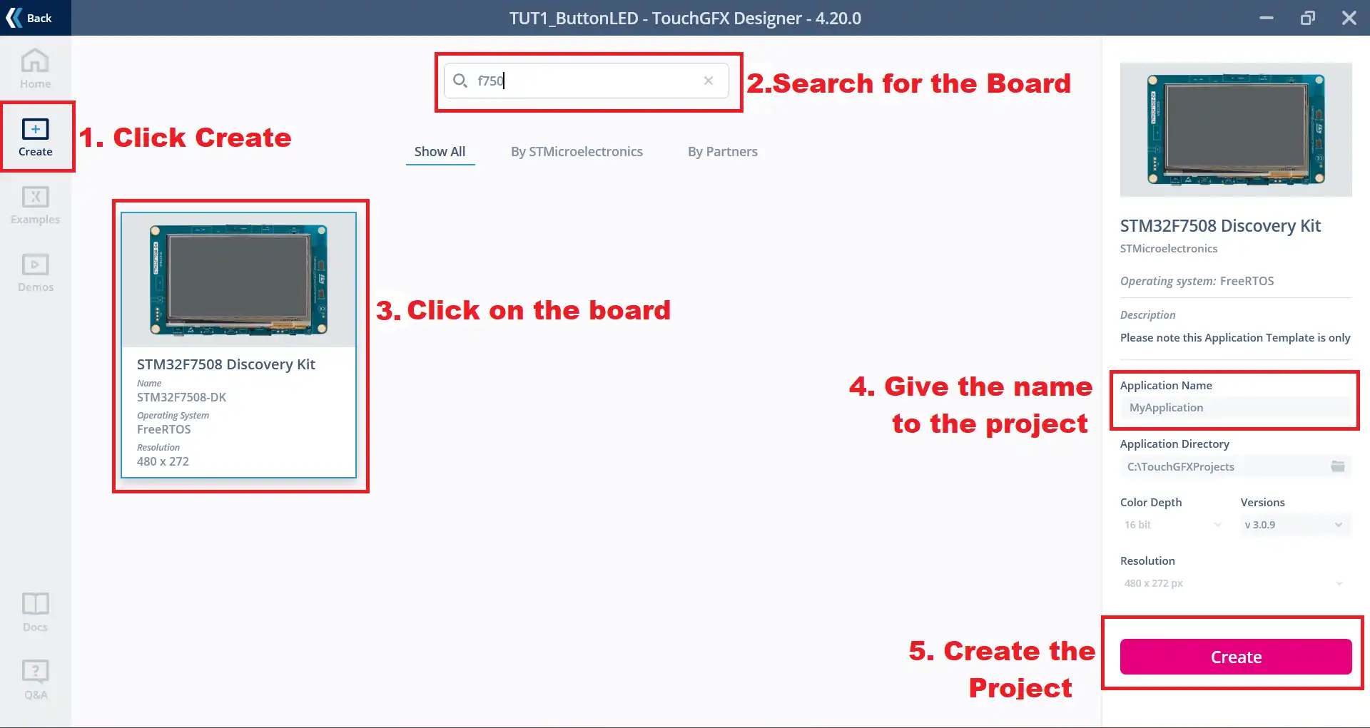
- To begin, open TouchGFX Designer and click on the Create tab. This option allows you to start a new STM32 GUI project.
- Next, use the search bar to find your specific controller board. In this tutorial, we are working with the STM32F750 Discovery board, so type “STM32F750” into the search field. TouchGFX Designer will show a list of compatible boards.
- From the results, select the correct board for your project. After that, enter a suitable name for your project so it is easy to identify later.
- Finally, click the Create button. TouchGFX Designer will now generate the project framework, which becomes the foundation for your embedded GUI development with STM32.
Step 2: Build the GUI – Add Background and Toggle Button
Once the project is created in TouchGFX Designer, the next step is to design the graphical interface. In this part, we will add a background image to make the display look complete and then place a toggle button widget using deag-and-drop tools in touchGFX that will control the LED on the STM32 board.
Add the background Image
First thing we will do is, add the background image to our project. Make sure the image is in the PNG format and is of same resolution as the display.
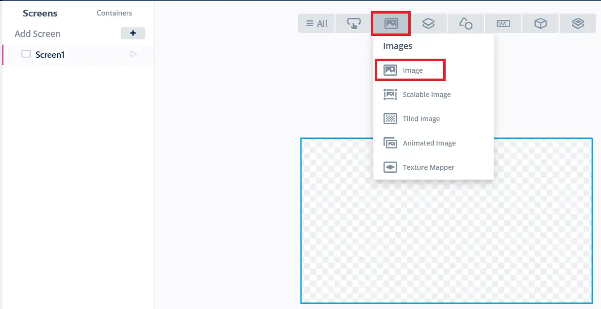
To add a background, move your cursor to the Image tab and select Image from the list of available widgets. As soon as you do this, an image placeholder will appear on the display screen.
Next, click on this image placeholder to open its properties panel. In the properties, go to the Image section and click on No Image. Then, press the “+” button to import your desired background image.
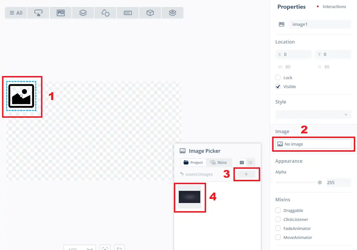
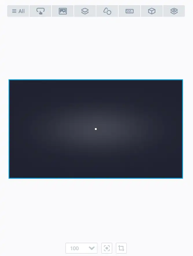
Once the image shows up in the Image Picker, select it, and TouchGFX will automatically place it on your display. You can now see a preview of how the final background will look on your STM32 GUI.
Add the Toggle Button
Now we have added the background image to our display, the next element we add is the toggle button. This button will be used to toggle the LED on the controller.
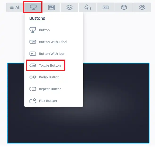
To add a button, move your cursor to the Buttons tab and select Toggle Button from the list of available widgets.
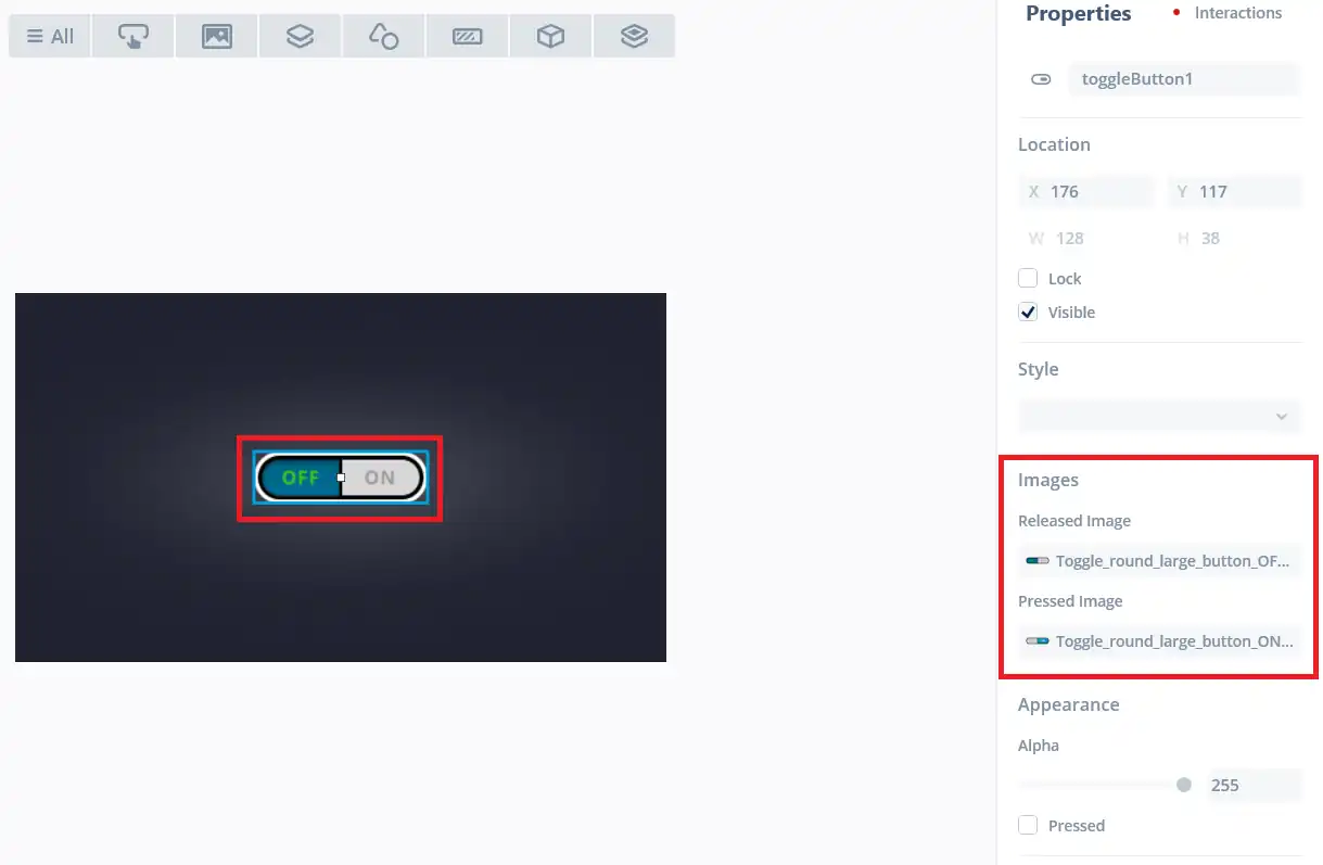
You can easily adjust the position of the toggle button by dragging it anywhere on the display area. When you click on the button, its properties panel will appear on the right side of the screen.
From here, you can customize the button according to your needs. For example, you can select whether the button should be round, rectangular, or another shape. This flexibility allows you to design a button that fits perfectly with the layout of your STM32 TouchGFX GUI project.
Step 3: Define Interaction in TouchGFX Designer
After adding the background and toggle button, the next step is to make the button functional. In TouchGFX Designer, this is done through the Interactions panel, where you can link button events to specific actions. By defining these interactions, you connect the graphical interface with the logic that will run on your STM32 microcontroller.
Interactions are basically limited to the screens on which you are adding them. For example, if you have 2 screens, the all the interactions added on screen 1 will only work on screen 1, similarly, interactions added on screen 2 will work only on Screen 2.
The image below shows how to add an interaction to Screen1.
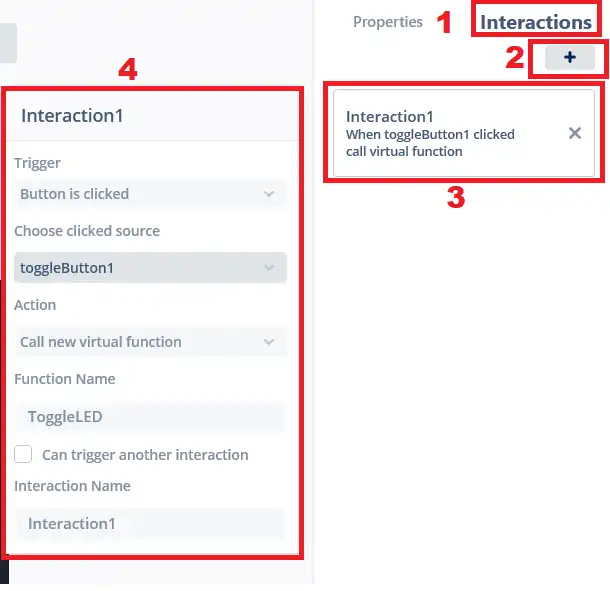
To begin, open the Interaction tab in TouchGFX Designer. Click the “+” button to create a new interaction. Once it appears, select it to edit the settings.
Next, choose the type of interaction you want on the screen. In this example, the Trigger is set to activate when the toggleButton1 is clicked. When this button is pressed, TouchGFX will call a new virtual function named ToggleLED.
We will later define this ToggleLED function inside STM32CubeIDE, where it will contain the code to toggle the LED connected to the STM32 controller.
Step 4: Generate Code & Open in STM32CubeIDE
Once the GUI design and interactions are complete, the next step is to generate the project code from TouchGFX Designer. This process creates all the necessary files and prepares the project so it can be compiled and linked with hardware functions.
After code generation, you can open the project directly in STM32CubeIDE, where you will write the function logic and integrate the STM32 hardware with the TouchGFX GUI.
Generate the Project
The following options can be seen on the bottom right corner of the TouchGFX Designer.
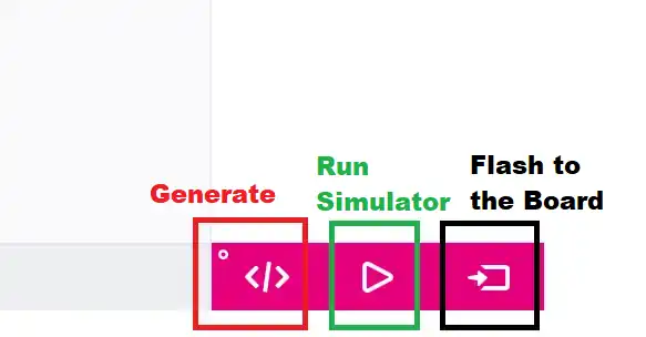
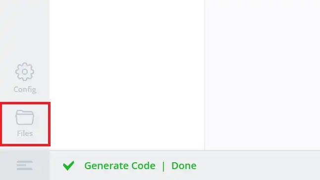
Here we have the options to Generate the project, or Run the simulator, or Flash the project to the board. Since we still need to write the code in the STM32CubeIDE, we will simply click on “</>” button generate the Project.
Once the project is generated, we can open the project folder by clicking the Files button on the bottom left corner of the TouchGFX Designer.
Open the project in cubeIDE
Clicking on the Files button will take you to the TouchGFX folder inside the main project folder.
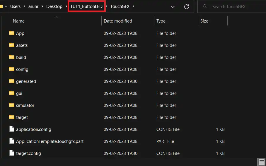
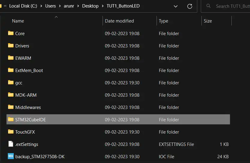
To open the project in STM32CubeIDE, first navigate to the main project folder that TouchGFX generated. Inside it, you will find a subfolder named STM32CubeIDE. Open this folder and double-click on the .project file or load this folder from the CubeIDE itself. This will launch the complete project in CubeIDE.
Once loaded, you can explore the project structure in STM32CubeIDE. The images below illustrate how the files are organized, showing where the TouchGFX GUI code and the STM32 hardware configuration files are located.
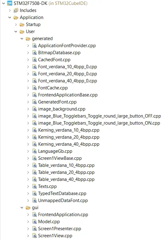
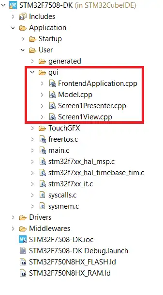
All the project assets are stored inside the generated folder. These files are automatically created by TouchGFX Designer and should not be modified, as they are meant only for reference. Instead, the main development work takes place in the gui folder, which is where you will add or edit code for your TouchGFX projects. Whenever you create or update GUI elements in TouchGFX Designer, the generated folder updates automatically, while your custom code stays safe inside the gui folder.
Step 5: Configure Hardware with STM32CubeMX
After setting up the GUI in TouchGFX and generating the project, the next step is to configure the hardware using STM32CubeMX. In this project, we will configure pin PA0 as an output to drive the LED.
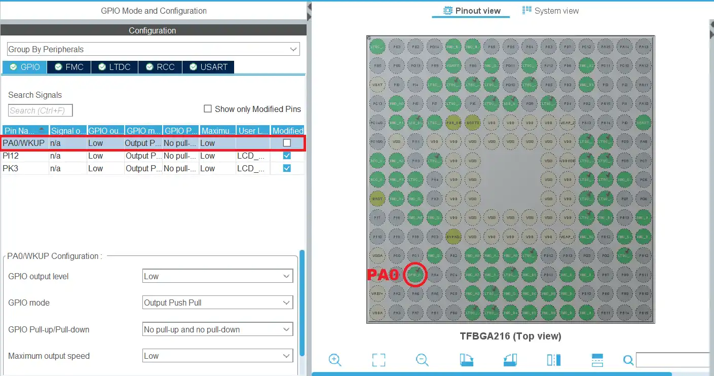
Set the pin PA0 as an output pin. This pin will be used to drive the LED. Once configured, you can connect the LED to PA0.
After setting PA0 as an output, click Save and then Generate Code in STM32CubeMX. This step creates all the low-level initialization files needed for your STM32 hardware. The generated code links directly with the TouchGFX project, so the interaction you defined in the GUI (the toggle button) can call functions that control the LED on PA0. In simple terms, CubeMX handles the hardware setup, while TouchGFX manages the graphics, and both come together inside STM32CubeIDE.
Step 6: Write the ToggleLED() Function in Code
With the hardware configured in CubeMX, the next step is to bring the GUI and hardware together through code. We will create the ToggleLED() function, which we defined in the ouchGFX, and will be called whenever the TouchGFX toggle button is pressed.
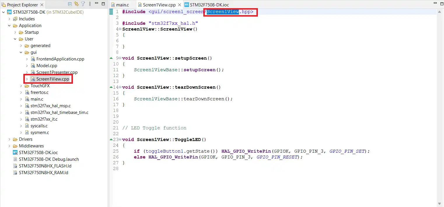
To connect the TouchGFX GUI button with the STM32 hardware, we need to edit two files: Screen1View.hpp and Screen1View.cpp.
1. Edit Screen1View.hpp
Open the file Screen1View.hpp. This file is not directly accessible, so you can open in from the Screen1View.cpp file as shown in the image below.
Inside the class declaration, add the following line: virtual void ToggleLED();
class Screen1View : public Screen1ViewBase
{
public:
    Screen1View();
    virtual ~Screen1View() {}
    virtual void setupScreen();
    virtual void tearDownScreen();

    virtual void ToggleLED();  // from the interaction
protected:
};

#endif // SCREEN1VIEW_HPPThis declares the ToggleLED() function, which we linked to the toggle button in TouchGFX Designer.
2. Edit Screen1View.cpp
Next, open Screen1View.cpp. At the top of the file, include the HAL header so you can access STM32 hardware functions: #include "main.h".
Now, define the ToggleLED() function. In this function, we will check the button state and then toggle the LED on pin PA0. For example:
#include "main.h"
// LED Toggle function
void Screen1View::ToggleLED()
{
	if (toggleButton1.getState()) HAL_GPIO_WritePin(GPIOA, GPIO_PIN_0, GPIO_PIN_SET);
	else HAL_GPIO_WritePin(GPIOA, GPIO_PIN_0, GPIO_PIN_RESET);
}This code reads the state of toggleButton1. When the button is pressed, it turns the LED ON. When released, it turns the LED OFF.
With this setup, the TouchGFX GUI is now fully linked to the STM32 hardware, and pressing the button on the display will directly control the LED.
Step 7: Build, Flash & Test
Now that the GUI and hardware code are ready, the next step is to build the project and flash it to your STM32 board using STM32CubeIDE. This process will compile all the code, load the firmware onto the microcontroller, and let you test the interaction between the TouchGFX GUI and the LED.
1. Build the Firmware
- In STM32CubeIDE, click on the Build Project icon (hammer symbol) in the toolbar, or go to Project > Build Project.
- The IDE will compile all source files, including the TouchGFX GUI code and the hardware initialization code generated by CubeMX.
- Check the console for any build errors. If the build is successful, CubeIDE will create a binary file that can be flashed to the board.
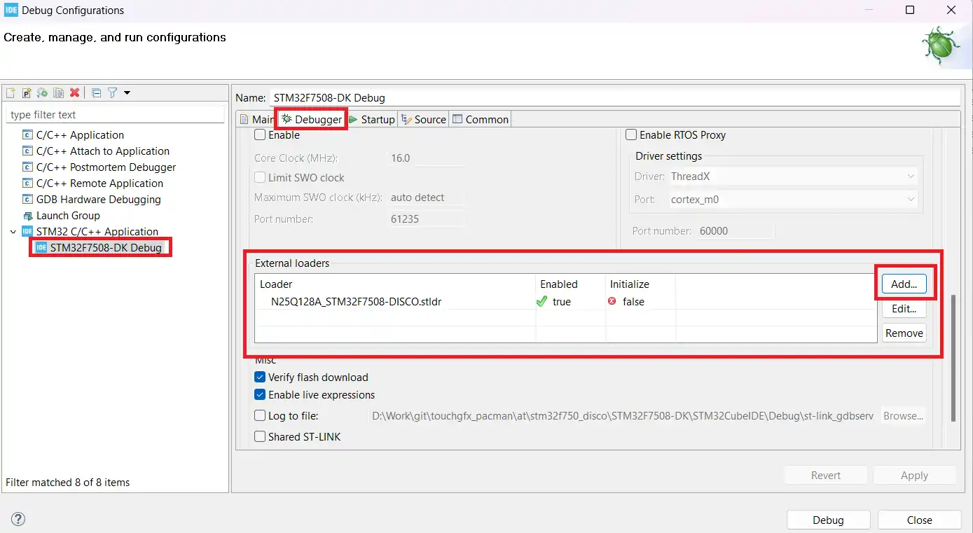
2. Configure the External Loader
Before flashing the code, make sure to select the correct External Loader in the debugger settings. Many STM32 development boards store images, fonts, and other large assets from TouchGFX Designer in external flash memory. If you do not enable the external loader, the firmware may fail to flash correctly. In some cases, the firmware runs, but the display remains blank because the GUI assets cannot load from external memory.
By enabling the external loader, we ensure that the images and fonts are properly loaded from the external flash and displayed on the screen. The image below shows where to configure the external loader option in STM32CubeIDE.
3. Flash the Firmware
- Connect your STM32F750 Discovery board to the computer using a USB cable.
- Click the Debug or Run button in STM32CubeIDE.
- The IDE will erase the board’s flash memory and load your newly built firmware.
- Once the process is complete, the program will start running automatically on the microcontroller.
4. Test the Project
- Look at the display on your Discovery board. You should see the GUI with the background and the toggle button.
- Press the toggle button on the screen. The LED connected to pin PA0 will turn ON when the button is pressed.
- Press the button again to toggle it off, and the LED will turn OFF.
At this point, your TouchGFX STM32 project is fully functional: the GUI we built in TouchGFX Designer is controlling real hardware through STM32CubeIDE.
Step 8: Results & Verification
By pressing the toggle button on the display, you can observe how the TouchGFX GUI interacts directly with the STM32 hardware. The LED connected to pin PA0 changes its state based on the button input, confirming that the setup works as expected.
The images below demonstrate this behavior:
- In the first image, the toggle button is in the OFF state, and the LED remains OFF.
- In the second image, the toggle button is switched to the ON state, and the LED turns ON.
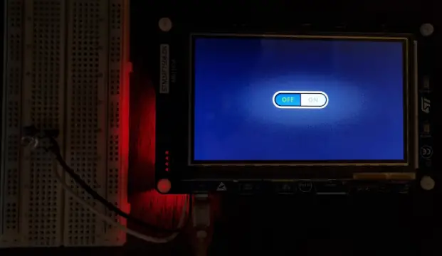
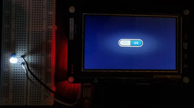
This animated GIF illustrates the live interaction between the TouchGFX GUI and the STM32 hardware.
Troubleshooting Tips
- Double-check that you configured pin PA0 as an output in CubeMX if the LED does not respond.
- Enable the external loader in STM32CubeIDE when images fail to appear on the display.
- Select the correct ST-LINK debugger in CubeIDE to ensure proper flashing and debugging.
- Rebuild the project whenever GUI changes do not show up on the board.
Conclusion
This tutorial showed how to connect a TouchGFX GUI with STM32 hardware by controlling an LED using a toggle button. You now understand the complete workflow—designing in TouchGFX Designer, configuring GPIO in STM32CubeMX, and coding logic in STM32CubeIDE.
For more learning, explore the full TouchGFX tutorial series. You can also check out Part 2: How to Use TextArea and Wildcards to enhance your GUI with text elements.
Browse More TouchGFX Tutorials

TouchGFX #3. Sending data to UI || MVP

TouchGFX#4. Sending data from another task || Gauge || Animation

TouchGFX #5. Data from UART to UI
TouchGFX #6. How to Build a Multiscreen Project

TouchGFX #7. How to implement on screen keyboard

TouchGFX #8. Send data from GUI to MCU
TouchGFX LED Toggle Project Download
STM32 TouchGFX Toggle LED FAQs


Hi i tried the same with stm32h753i-eval2 the gui is printing on the lcd screen but its not getting on/off touch is not working while debbugging it it reaches hardfault error
Check the events which are leading to hardfault. You can see the function sequence on the left side of the debugger.
Hello Prabhu, i have the same problem!
Have u found a solution for this error?
Hi I tried the same with STM32F769NI DISCO board. I am getting an error:
no declaration matches ‘void Screen1View::Led()’ Screen1View.cpp /STM32F769I_DISCO/Application/User/gui line 158 C/C++ Problem
You missed some definition, probably the LED() function’s definition in the view.cpp file.
Hi Prabhu,
I have the same problem even I followed every step
Have you found the solution for this error?
Tks in advanced,
Open Screen1View.hpp file and add the prototype for the function. As below..
virtual void ToggleLED();// interaction1
Hello
Your tutorials are excellent
I have a problem, which is that I can’t write a graphic program to control the light intensity, and by writing GUI, you are teaching about ADC modules such as loadcell and PMW contorell.