Interface DS3231 RTC module with STM32
Today in this tutorial we are going to interface DS3231 RTC module with STM32. The module works on I2C communication protocol, and therefore we need only 2 wires to interface it with the microcontroller.
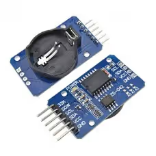
The following are the features of DS3231 RTC module
- Highly Accurate RTC Completely Manages All Timekeeping Functions
- Real-Time Clock Counts Seconds, Minutes, Hours, Date of the Month, Month, Day of the Week, and Year, with Leap-Year Compensation Valid Up to 2100
- Digital Temp Sensor Output: ±3°C Accuracy
- Register for Aging Trim
- Two Time-of-Day Alarms
- Programmable Square-Wave Output Signal
- Simple Serial Interface Connects to Most Microcontrollers
- Fast (400kHz) I2C Interface
- Battery-Backup Input for Continuous Timekeeping
- 3.3V Operation
In this Tutorial, we are going to cover the RTC and the temperature section. The remaining features like ALARM, and square wave will be covered in upcoming tutorials.Let’s first start by setting up the CubeMx for the I2C.
VIDEO TUTORIAL
You can check the video to see the complete explanation and working of this project.
CubeMX Setup
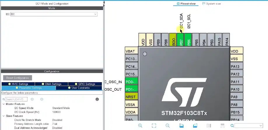
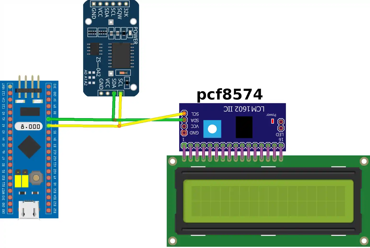
In the setup above, I have enabled the I2C peripheral. Both, the RTC module, and LCD will be connected to this same I2C. The connection is Shown below
There is nothing special about Interfacing DS3231 with any microcontroller. It’s basically a memory device, which we can write the data to and read the data from. Just like any other memory device, we have to do the following in order to perform the read/write operation
- Select the device by sending the device address on the I2C line
- Select the memory address that you want to access
- write/read the data to the address
The following is the picture from the datasheet of the device. It shows the registers available in the DS3231 for writing and reading data.
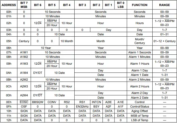
As I mentioned, in this tutorial we are only going to interface the RTC and temperature part. therefore we are interested in the registers ranging from address 00h to 06h for the clock and date, and 10h 11h for the temperature.
Some Insight into the CODE
First of all I have defined the address of the device as mentioned in it’s datasheet.
#define DS3231_ADDRESS 0xD0The data stored in the TIME and DATE Registers is in the BCD (Binary Coded Decimal) format, so first we need the functions to convert from decimal to bcd and other way around. The following are the functions to do so
// Convert normal decimal numbers to binary coded decimal
uint8_t decToBcd(int val)
{
  return (uint8_t)( (val/10*16) + (val%10) );
}
// Convert binary coded decimal to normal decimal numbers
int bcdToDec(uint8_t val)
{
  return (int)( (val/16*10) + (val%16) );
}Before reading time, we need to set the time. The following function is defined to set the time. The parameters are self explanatory.
/* function to set time */

void Set_Time (uint8_t sec, uint8_t min, uint8_t hour, uint8_t dow, uint8_t dom, uint8_t month, uint8_t year)
{
	uint8_t set_time[7];
	set_time[0] = decToBcd(sec);
	set_time[1] = decToBcd(min);
	set_time[2] = decToBcd(hour);
	set_time[3] = decToBcd(dow);
	set_time[4] = decToBcd(dom);
	set_time[5] = decToBcd(month);
	set_time[6] = decToBcd(year);

	HAL_I2C_Mem_Write(&hi2c1, DS3231_ADDRESS, 0x00, 1, set_time, 7, 1000);
}We have to convert the decimal values to the corresponding BCD value before writing them to the registers.
I am using HAL_I2C_Mem_Write to write data directly to the address given. As you can see above, I have used single address (0x00), and written 7 bytes of data to it. This operation is called Multi-Write, and is supported by pretty much every memory device. The address gets incremented automatically, when you write the next byte of data.
This way it is similar to as writing 1 byte of data to each of the first 7 registers (00h to 06h). The function is defined as follows
/**
  * @brief  Write an amount of data in blocking mode to a specific memory address
  * @param  hi2c Pointer to a I2C_HandleTypeDef structure that contains
  *                the configuration information for the specified I2C.
  * @param  DevAddress Target device address: The device 7 bits address value
  *         in datasheet must be shifted to the left before calling the interface
  * @param  MemAddress Internal memory address
  * @param  MemAddSize Size of internal memory address
  * @param  pData Pointer to data buffer
  * @param  Size Amount of data to be sent
  * @param  Timeout Timeout duration
  * @retval HAL status
  */
HAL_StatusTypeDef HAL_I2C_Mem_Write(I2C_HandleTypeDef *hi2c, uint16_t DevAddress, uint16_t MemAddress, uint16_t MemAddSize, uint8_t *pData, uint16_t Size, uint32_t Timeout);Get_Time function is used to read the time and date from the module, and save the data into the time structure.
void Get_Time (void)
{
	uint8_t get_time[7];
	HAL_I2C_Mem_Read(&hi2c1, DS3231_ADDRESS, 0x00, 1, get_time, 7, 1000);
	time.seconds = bcdToDec(get_time[0]);Get
	time.minutes = bcdToDec(get_time[1]);
	time.hour = bcdToDec(get_time[2]);
	time.dayofweek = bcdToDec(get_time[3]);
	time.dayofmonth = bcdToDec(get_time[4]);
	time.month = bcdToDec(get_time[5]);
	time.year = bcdToDec(get_time[6]);
}As seen above, HAL_I2C_Mem_Read is used to read the memory address (0x00) directly, and we are reading 7 bytes of data from this address, so 1 byte will be read from the each incremented address. We also need to convert this data into the decimal format before displaying it.
Get_Temp reads the temperature and than returns a float value
float Get_Temp (void)
{
	uint8_t temp[2];
	HAL_I2C_Mem_Read(&hi2c1, DS3231_ADDRESS, 0x11, 1, temp, 2, 1000);
	return ((temp[0])+(temp[1]>>6)/4.0);
}As you can see above, we are reading 2 bytes of data from the 0x11 (11h) address. The LSB (temp[1]) needed to be shifted to the right by 6 places as shown in the picture below

Temperature is represented as a 10-bit code with a resolution of 0.25°C and is accessible at location 11h and 12h. The temperature is encoded in two’s complement format. The upper 8 bits, the integer portion, are at location 11h and the lower 2 bits, the fractional portion, are in the upper nibble at location 12h. For example, 00011001 01b = +25.25°C.
The function force_temp_conv forces the conversion of the temperature by writing into the CONV bit of the control register at the location 05h
void force_temp_conv (void)
{
	uint8_t status=0;
	uint8_t control=0;
	HAL_I2C_Mem_Read(&hi2c1, DS3231_ADDRESS, 0x0F, 1, &status, 1, 100);  // read status register
	if (!(status&0x04))  // if the BSY bit is not set
	{
		HAL_I2C_Mem_Read(&hi2c1, DS3231_ADDRESS, 0x0E, 1, &control, 1, 100);  // read control register
		HAL_I2C_Mem_Write(&hi2c1, DS3231_ADDRESS, 0x0E, 1, (uint8_t *)(control|(0x20)), 1, 100);  // write modified control register with CONV bit as'1'
	}
}The main function
  lcd_init ();

  Set_Time(00, 03, 14, 5, 3, 1, 19);
  while (1)
  {
	  Get_Time();
	  sprintf (buffer, "%02d:%02d:%02d", time.hour, time.minutes, time.seconds);
	  lcd_put_cur (0,0);
	  lcd_send_string(buffer);

	  sprintf (buffer, "%02d-%02d-20%02d", time.dayofmonth, time.month, time.year);
	  lcd_put_cur(1, 0);
	  lcd_send_string(buffer);

	  force_temp_conv();

	  TEMP = Get_Temp();

	  lcd_put_cur(0, 10);

	  sprintf (buffer, "%f", TEMP);

	  lcd_send_string(buffer);

	  HAL_Delay(500);
}We have to set the time once in the main function, and than we can always read the time in the while loop.
One more very important thing. After setting the time, you must flash the code again with the Set_Time function as commented out as shown below
// Set_Time(00, 03, 14, 5, 3, 1, 19);So, just comment out the function and flash again. This is to ensure that, if microcontroller resets, the RTC won’t start from this time again.
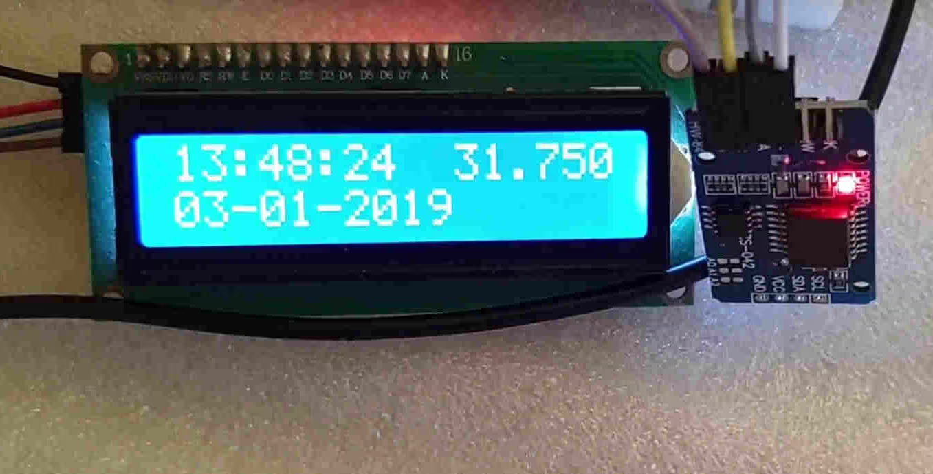
RESULT


First of all thank you for the informative video. I have a question regarding the used adresses in set_time and get_time function. Why is the DS3231_Adress not equal to 0xD0 with respect to HAL_I2C_Mem_Write. The DS3231 is normally 0x68 and with “write” command should be left shifted with 0 which leads to a new address of 0xD0. I cant seem to get correct values from the realtimeclock module.
Hello Sir, I’m modify your program to press switch for the first time to set the time, Thanks.
if(HAL_GPIO_ReadPin(GPIOC, GPIO_PIN_13) == GPIO_PIN_RESET)
{
Set_Time(30, 7, 16, 7, 10, 4, 23);
}
good solution..
Hello, thank you very much, sir.
Thanks for the explanation of how to get the RTC running on a STM32 MCU.
Two remarks on your code for the reading of the temperature:
1.: In your function force_temp_conv, you’re trying to compute the value of or-ing the control byte and converting it into a pointer with this code:
(uint8_t *)(control|(0x20))
What the code actually does is compute the value of (control | 0x20) and the typecasting it to a pointer, which points to a uint8_t at address (control | 0x20), which is not what you actually want. Which would be something like
(uint8_t *)&(control|(0x20)), which is not possible since the computation doesn’t allocate the memory for you.
I have no better solution than to compute the value first, store it in control and then pass a pointer to the address of control in to the call:
control |= 0x20;
HAL_I2C_Mem_Write(&hi2c1, DS3231_ADDRESS, 0x0E, 1, (uint8_t *)&control, 1, 100);
2.: The code for reading the temperature has problems with negative values. You should typecast type[0] from an uint8_t to an int8_t.
Thanks again for the good introduction.
Christof
Dear Sir,
Thanks for your post.
Could you please show me how to store data in DS3231 EEPROM and how we can read data from EEPROM after system switched on several days after.
i have one doubt , cording to datasheet , 0x00 is for seconds so how you are setting time by pushing all the things(hour,minute,seconds) in 0x00 .
I think you will understand my issue and tell me the reason behind it.
we can write multiple data starting at 0x00. one 1 data byte get stores at 0x00, and for the next data byte, the register will automatically increment to 0x01. That’s how the devices work
Hi Sir, thanks for the video, please update features like alarm.