WS2812 LEDs using SPI
Few months ago I covered how to interface WS2812 LED with STM32 using the Timer’s PWM mode. This is yet another tutorial on the WS2812 Addressable LEDs but today we will use SPI.
VIDEO TUTORIAL
You can check the video to see the complete explanation and working of this project.
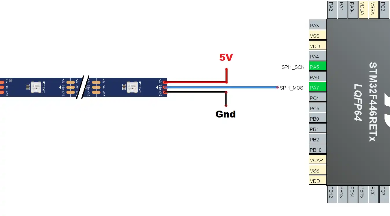
We will only use the SPI MOSI pin to send the data to the LEDs. So this setup still needs only 1 pin to interface the WS2812 driver to the MCU.
SPI is being used because of its high baud rate. The bit timing required for the LEDs is very low (around 0.4us) and with SPI we can achieve this.
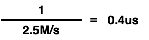
The idea is very simple. If we set the SPI baud rate at 2.5Mbits/s, each bit would represent a pulse of 0.4us.
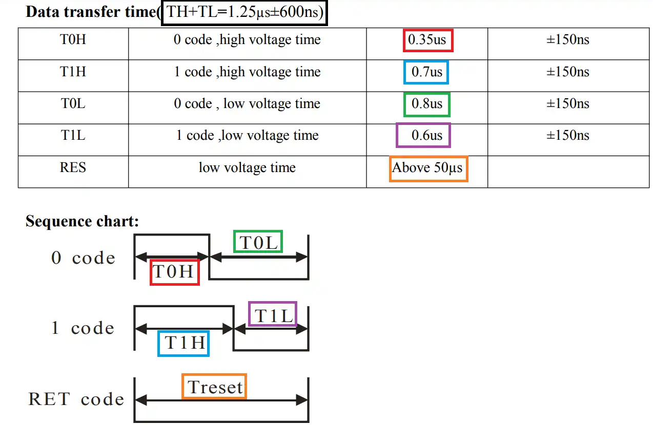
According to the datasheet of the WS2812, a bit is considered as 0 if the signal remains HIGH for 0.35us and LOW for 0.8us. And for a bit to be considered as a 1, the signal remains HIGH for 0.7us and LOW for 0.6us. Of course this is flexible with an error up to ±150ns.
Also the reset signal is supplied by pulling the data line low for more than 50us.
We will use 3 SPI bits to represent a single bit for the WS2812. The 3 SPI bits will have the time period of 1.2us (0.4*3).
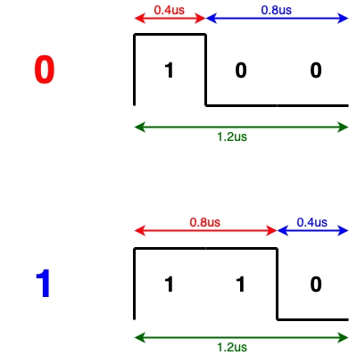
As shown above, to send a 0 to the driver, we can send the bits 100. This will keep the pulse high for 0.4us and low for 0.8us. Which is as per the timing required for a 0 in the datasheet.
Similarly to send a 1 to the driver, we can send the bits 110. This will keep the pulse high for 0.8us and low for 0.4us. Which is the acceptable timing for a 1 as per the datasheet.
We will see this in more details in the code section below. Let’s start with the setup.
CubeMX Setup
We just need to enable the SPI and set the baud rate to 2.5Mbits/sec.
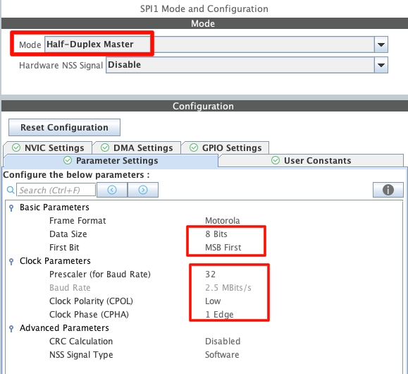
- Here the SPI is configured in Half Duplex Mode as we only need to send the data to the driver. We are not accepting any data from it.
- The Data Size is 8 bit as we will be storing only 3 bits for each driver bit. The data must be sent as the MSB first.
- The Prescaler is setup in a way that we get the baud rate of 2.5MBits/s.
- The CPOL is Low and CPHA is 1 Edge. This is basically MODE 0 of the SPI.
In Half Duplex Mode, the 2 pins gets auto selected, i.e The SCK (Clock) and the MOSI (Data out) pins. Out of these we will only use the MOSI pin to connect to the Data pin of the WS2812.
The code
I have created separate library files for the WS2812_Spi. So most of the code is written in the WS2812_spi.c file.
Definitions
#define NUM_LED 8
uint8_t LED_Data[NUM_LED][4];

extern SPI_HandleTypeDef hspi1;

#define USE_BRIGHTNESS 1
extern int brightness;We will first define the number of LEDs in the strip or matrix. Then create a matrix with the number of rows same as the LEDs and 4 columns.
The 3 columns will be used to store the cooler codes (RGB) and the 4th column will be used to store the LED number.
Then define the SPI handler as the external variable. The main definition of this handler is in the main file.
I have also included the brightness control (Not very accurate but works). You can decide whether to use the brightness feature (setting it to 1) or not to use (by setting it to 0). An external integer, brightness, is defined to hold the brightness value. This variable is actually defined in the main function and can have the value from 0 to 100.
The setLED function
The setLED function will be used to store the cooler code for the respective LED in the matrix we just created.
void setLED (int led, int RED, int GREEN, int BLUE)
{
	LED_Data[led][0] = led;
	LED_Data[led][1] = GREEN;
	LED_Data[led][2] = RED;
	LED_Data[led][3] = BLUE;
}Here @led is the number of LED (0 to NUM_LED-1) where we want to store the RGB code. The rest of the parameters are the color codes.
The first element of the matrix stores the LED number, and the rest of them stores the color codes. Note that I am storing the GREEN color first. This is because as per the datasheet of the driver, the color data is sent in the GRB format.

Send Data to the Driver
To send the data to the driver, we first need to extract each bit of the color data and then assign the 3 SPI bits for each one of them.
void ws2812_spi (int GREEN, int RED, int BLUE)
{
#if USE_BRIGHTNESS
	if (brightness>100)brightness = 100;
	GREEN = GREEN*brightness/100;
	RED = RED*brightness/100;
	BLUE = BLUE*brightness/100;
#endif
	uint32_t color = GREEN<<16 | RED<<8 | BLUE;
	uint8_t sendData[24];
	int indx = 0;

	for (int i=23; i>=0; i--)
	{
		if (((color>>i)&0x01) == 1) sendData[indx++] = 0b110;  // store 1
		else sendData[indx++] = 0b100;  // store 0
	}

	HAL_SPI_Transmit(&hspi1, sendData, 24, 1000);
}Here we will first combine the 3 color bytes to make a single 24 bit color data. The sendData array is defined with 24 elements to store 3 bits for each color data bit.
Now in the for loop we will start extracting each bit of the color data from the most significant bit first. If the bit is a 1, we will store the SPI bits 110 in the respective element in the array. Otherwise if the bit is a 0, we will store the bits 100 at the respective element in the array.
Basically we will start extracting from the 23rd bit (G7) of the color data, and store the respective SPI data in the sendData[0]. When we will send this array to the SPI, the element [0] will be sent first, and hence in a way we are sending the 23rd bit (G7) of the color data first.
We also use the brightness value to control the colors. The RGB color values will change based on the brightness value before we even combine them.
Once all the extraction is finished, we will send all 24 bytes to the SPI.
The actual send function
The above function is sued to send the data for a single LED to the driver. But in reality we need to send the data for all the LEDs every time we make changes even in a single LED. The WS2812_Send function will be used to call the above function for all the LEDs.
void WS2812_Send (void)
{
	for (int i=0; i<NUM_LED; i++)
	{
		WS2812_Send_Spi(LED_Data[i][1],LED_Data[i][2],LED_Data[i][3]);
	}
	HAL_Delay (1);
}Here we will call the for loop as many times as the number of LEDs we have connected in series. For each LED, we will send the data via the SPI.
The data is stored in the LED_Data matrix we defined earlier in the file. The GREEN color is stored in the 1st element, then the RED in the 2nd and the BLUE in the 3rd.
Once all the data is sent, we will give a delay of 1ms for the RESET code. As per the datasheet we need to keep the line LOW for more than 50us to indicate that all the data for the LEDs has been sent.
The main function
In the main function we will send the color codes to the respective LEDs. For the testing purpose I am setting all the LEDs to RED GREEN and BLUE for 1 second each.
 while (1)
  {
	  for (int i=0; i<4; i++)
	  {
		 setLED(i, 255, 0, 0);
	  }
	  WS2812_Send(5);
	  HAL_Delay(1000);

	  for (int i=0; i<4; i++)
	  {
		 setLED(i, 0, 255, 0);
	  }
	  WS2812_Send(5);
	  HAL_Delay(1000);

	  for (int i=0; i<4; i++)
	  {
		 setLED(i, 0, 0, 255);
	  }
	  WS2812_Send(5);
	  HAL_Delay(1000);
}In the code above, I am sending all the three colors 1 by 1, each after a delay of 1 second. Below is the result of this code.
As you can see the LEDs are displaying all 3 colors after a delay of 1 second each.
We can display any color with its RGB code. For example, below is the code for displaying some random color on a particular set of LEDs.
for (int i=0; i<8; i++)
{
setLED(i, 0, 0, 0);
}
WS2812_Send();
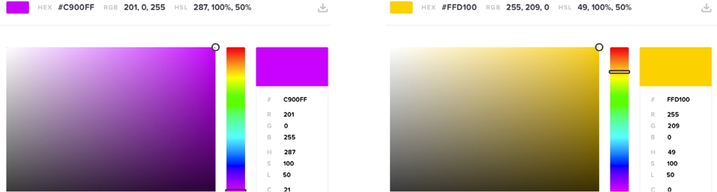
setLED(0, 201, 0, 255);
setLED(4, 255, 209, 0);
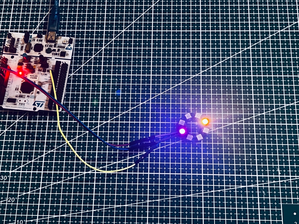
WS2812_Send();Here I am first setting all the LEDs to 0, so to turn them off. Then only the LED 0 and LED 4 will display particular colors with the mentioned RGB values.
Below are the images showing the output.


Sorry maybe I’m being dense but I don’t understand how you can store 3 bits in bytes and only transmit 3 bits out of 8 by spi. Or do you add 5 zeros after each bit ?
yes they are 0’s
Could i suggest using a DMA for this? Connecting 400 LEDs or similar has a real CPU load/takes a relatively long time for the CPU otherwise.
Sure you can use DMA too.
Thank you so much for the detailed explanation. It helped me to make my led strip work in my luckfox pico pro
Thank you for posting. For a Infineon PSoC CY8C4247AZI dev. kit the achievable SPI Bit Rate of 2.6Mbps works well.
The presented code undoubtedly works but is very inefficient. The code sends 3 bits for every 8 bit SPI message. At the very leas 6 bits can be packed into each message without too much effort. With a bit more effort all 8 bits of the SPI message can be used.
yes ofcourse. This was made this way to keep things simple so that everyone could understand the process. Rest is upto you on how to implement it more efficiently.
Here is optimized code.
union LED_colors_decoder_union
{
uint32_t GRB_colors_32;
uint8_t GRB_colors_bytes[4];
};
bool decode_led_colors(unsigned char* buffer)
{
//declare the required unions.
union LED_colors_decoder_union incoming_colors;
union LED_colors_decoder_union outgoing_decoded_stream;
// reset the values as they may be filled with garbage.
outgoing_decoded_stream.GRB_colors_32 = 0;
incoming_colors.GRB_colors_32 = 0;
unsigned int LED_tail = 0;
int i;
int j;
int k = 0;
int l;
// cycle thrugh the entire LED series and decode it into the required SPI message.
for (l = 0; l < number_of_LEDs; l++)
{
//Grab the 3 colors for a single LED.
incoming_colors.GRB_colors_bytes[0] = LED_get_color(LED_tail + 2);
incoming_colors.GRB_colors_bytes[1] = LED_get_color(LED_tail + 1);
incoming_colors.GRB_colors_bytes[2] = LED_get_color(LED_tail + 0);
LED_tail += 3;
for (i = 0; i < 3; i++)
{
for (j = 0; j < 8; j++)
{
//compare each bit of the color and replace that bit with a 3 bit combination.
if (incoming_colors.GRB_colors_32 & 0x800000)
{
//if the bit was a one replace it with 0b110
incoming_colors.GRB_colors_32 <<= 1;
outgoing_decoded_stream.GRB_colors_32 <<= 3;
outgoing_decoded_stream.GRB_colors_32 |= 0b110;
} else
{
//if the bit was a zero replace it with 0b100
incoming_colors.GRB_colors_32 <<= 1;
outgoing_decoded_stream.GRB_colors_32 <<= 3;
outgoing_decoded_stream.GRB_colors_32 |= 0b100;
}
}
//Now write those 3 resultant bytes to the buffer.
buffer[k] = outgoing_decoded_stream.GRB_colors_bytes[2];
k++;
buffer[k] = outgoing_decoded_stream.GRB_colors_bytes[1];
k++;
buffer[k] = outgoing_decoded_stream.GRB_colors_bytes[0];
k++;
outgoing_decoded_stream.GRB_colors_32 = 0;
}
}
//fill in the last 3 buffer spots with zeroes for the message brake.
buffer[k] = 0;
k++;
buffer[k] = 0;
k++;
buffer[k] = 0;
k++;
return true;
};