Home ▸ STM32 Tutorials ▸
How to add Touch Interface to the LCD
This tutorial is the PART2 of the Interfacing the LCD via the FMC peripheral. In the PART1 we covered how to connect the LCD via the FSMC, How to configure the FSMC and how to turn ON the display. Today we will see how to add the touch interface to our Display.
I am using the STM32F412 discovery development board. The LCD is already attached to this board and it is connected via the FSMC. The LCD uses the ST7789H2 controller and FT6X06 touch controller.
VIDEO TUTORIAL
You can check the video to see the complete explanation and working of this project.
Connection
I have already covered the LCD connection via the FSMC in the PART1 of this series. Today we will just focus on the touch controller.
Below is the image showing the schematic of the touch controller .
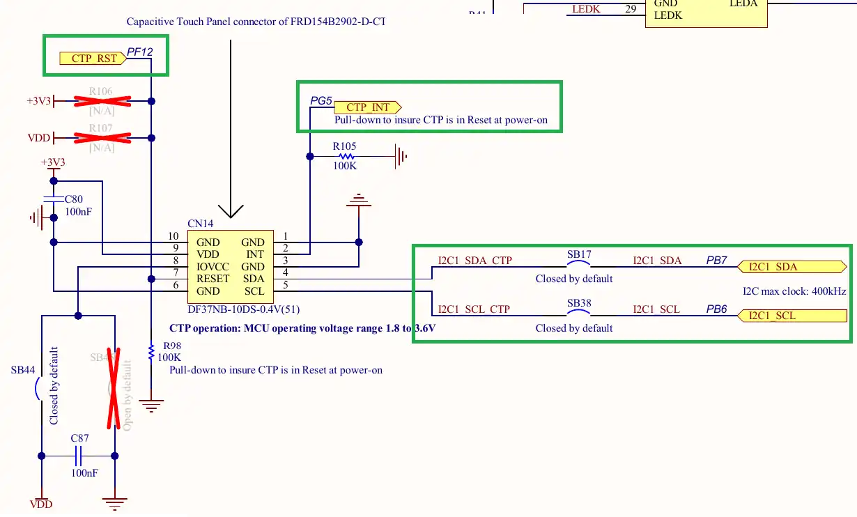
The touch controller FT6X06 uses the I2C to communicate with the MCU. In the image shown above you can see the I2C SDA line is connected to the pin PB7 (I2C1 SDA) and the SCL line is connected to the pin PB6 (I2C1 SCL).
Other than the I2C pins, we also the have the pin for the Interrupt and Reset. The Interrupt pin is used to send the interrupt signal to the MCU whenever a touch is detected. We will leave this pin disconnected as we will not be using the interrupt. The Reset pin is used to reset the touch controller and it is connected to the pin PF12 of the MCU.
The cubeMX is setup according to this configuration. Below is the image showing the cubeMX configuration.
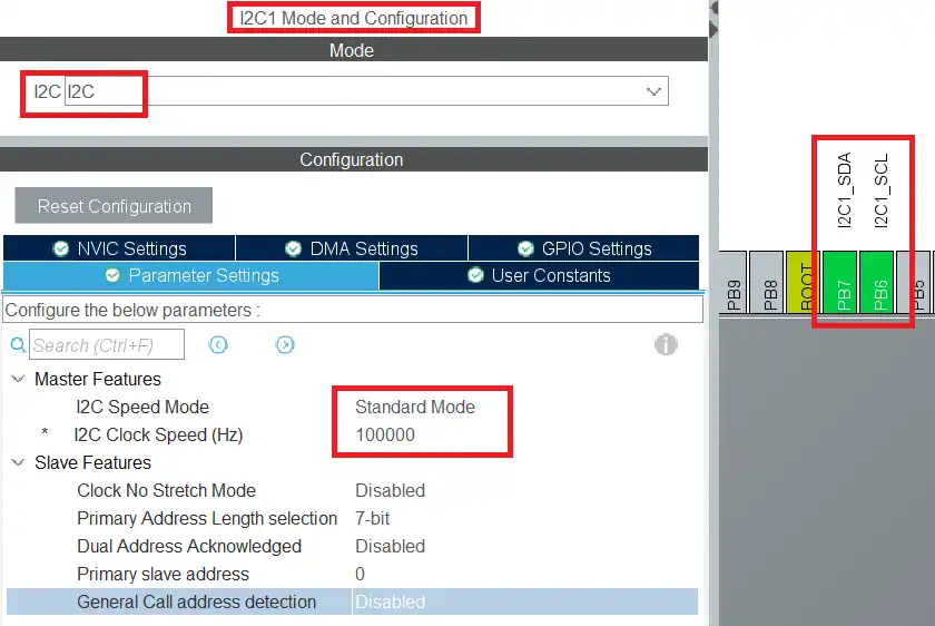
As shown above, the I2C1 is configured in the standard mode with the clock speed of 100KHz. The pins PB6 and PB7 got selected as the SCL and SDA pins. These pins are as per the schematic of the touch controller.
We also need to set the pin PF12 as the output so that we can use it to control the touch reset.
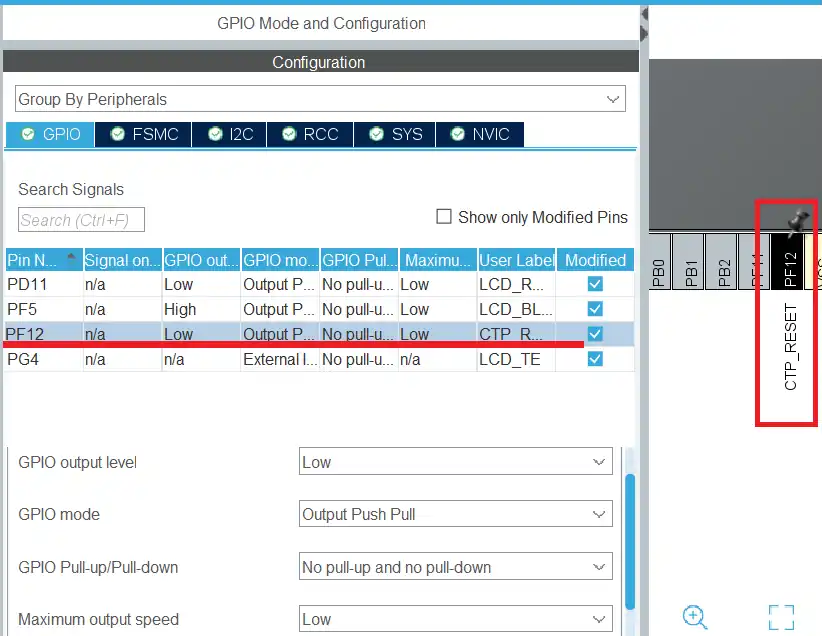
I have renamed the pin PF12 as CTP_RESET.
The Code
I got the Library for the ft6x06 from the ST’s database. You can get it inside the STM32Cube folder in your computer at STM32Cube\Repository\STM32Cube_FW_F4_V1.28.0\Drivers\BSP\Components\ft6x06.
There are other touch controller libraries available inside these folders as well. But all these libraries do not include functions to connect the touch controller to the MCU. We need to define those functions ourselves and their code will change based on how the touch controller is connected to the MCU. We can write the functions in terms of I2C, SPI or even using the normal GPIO operations.
Below is the image showing the functions needed to be defined. The functions are defined as the external functions in the FT6X06 header file and they will be used to connect the display to the MCU.
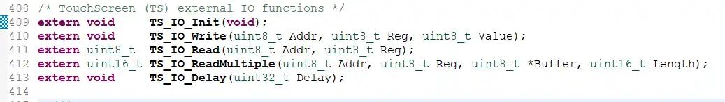
We will create new source an header files to define these functions separately. I am naming the files as LCD_Touch.c and LCD_Touch.h.
LCD_Touch.c file
First we have the initialization function.
void TS_IO_Init(void)
{
	HAL_GPIO_WritePin(CTP_RESET_GPIO_Port, CTP_RESET_Pin, GPIO_PIN_RESET);
	HAL_Delay(10);
	HAL_GPIO_WritePin(CTP_RESET_GPIO_Port, CTP_RESET_Pin, GPIO_PIN_SET);
	HAL_Delay(10);
}Here we will reset the CTP Reset pin and then set it again after some time. This will reset the touch controller.
Next is the function to write the data.
void TS_IO_Write(uint8_t Addr, uint8_t Reg, uint8_t Value)
{
  HAL_I2C_Mem_Write(&hi2c1, Addr, Reg, 1, &Value, 1, 100);
}The IO Write function is used to write the data to the touch controller. Since we are using the I2C to interface the touch controller, the data will be written using the same.
We will use the function HAL_I2C_Mem_Write to write the data into a particular Register. The parameters of this function are as follows:
- @Addr is the slave address and it will be passed from the IO_Write function.
- @Reg is the address of the memory location inside the touch controller, where the data will be written.
- @1 denotes the size of the Register memory address. 1 means the memory address is 8 bit in size and 2 means 16 bit in size.
- @value is the value we want to store in the register. We need to pass the address of the value variable as we are only writing 1 byte.
- @1 denotes that the size of the data is 1 byte.
- @100 milliseconds is the timeout for this function
Next we have the function to read the data.
uint8_t  TS_IO_Read(uint8_t Addr, uint8_t Reg)
{
	uint8_t data;
	HAL_I2C_Mem_Read(&hi2c1, Addr, Reg, 1, &data, 1, 100);
	return data;
}the IO_Read function is used to read the data from the touch controller’s memory.
We use the function HAL_I2C_Mem_Read to read the data from a particular memory location. The parameters of this function are as follows:
- @Addr is the slave address and it will be passed from the IO_Read function.
- @Reg is the address of the memory location inside the touch controller, where the data will be read from.
- @1 denotes the size of the Register memory address. 1 means the memory address is 8 bit in size and 2 means 16 bit in size.
- @data is the variable where the byte read will be stored. We need to pass the address of this variable as we are only reading only 1 byte.
- @1 denotes that the size of the data to be read is 1 byte.
- @100 milliseconds is the timeout for this function
Next is the function to read multiple data bytes.
uint16_t TS_IO_ReadMultiple(uint8_t Addr, uint8_t Reg, uint8_t *Buffer, uint16_t Length)
{
	return (HAL_I2C_Mem_Read(&hi2c1, Addr, Reg, 1, Buffer, Length, 1000));
}The function IO_ReadMultiple is used to read multiple data bytes starting from a given memory location. We use the same function HAL_I2C_Mem_Read to read the data bytes. The parameters used are as follows:
- @Addr is the slave address and it will be passed from the IO_ReadMultiple function.
- @Reg is the address of the memory location inside the touch controller, where the data reading will start from.
- @1 denotes the size of the Register memory address. 1 means the memory address is 8 bit in size and 2 means 16 bit in size.
- @Buffer is the pointer to the variable where the bytes read will be stored.
- @Length denotes the size of the data to be read. We pass it from the main function itself.
- @1000 milliseconds is the timeout for this function
At last we have the function for the delay.
void TS_IO_Delay(uint32_t Delay)
{
	HAL_Delay(Delay);
}Here we will just call the function HAL_Delay and pass the Delay parameter to this function.
The main Function
In the main function we will initialize the LCD first and then initialize the touch controller.
  ST7789H2_Init();
  LCD_Fill(0xF800, 0, 0, 240, 240);
  ft6x06_Init(0x70);  // 0x38>>1 = 0x70
ft6x06_TS_Start(0x70);The function ST7789H2_Init() is used to initialize the LCD and LCD_Fill(…) is used to fill the display with RED color in the background.
Then we will call the function ft6x06_Init to initialize the touch controller, and the function ft6x06_TS_Start to start reading the touches. These functions uses the slave address as the parameter.
The slave address for this controller is not mentioned in its datasheet, but you can find it on https://i2cdevices.org/addresses. Just search for ft6x06 and you can find the device address.
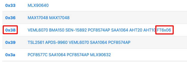
You can see the slave address is 0x38. This is a 7 bit address without including the R/W bit. The HAL uses 8 bit address, so we need to shift this address to the left by 1 place. 0x38<<1 = 0x70.
We will continuously read the touches inside the while loop.
  while (1)
  {
	  if (ft6x06_TS_DetectTouch(0x70))
	  {
		  ft6x06_TS_GetXY(0x70, &RAW_X, &RAW_Y);
	  }

	  HAL_Delay(100);
}The function ft6x06_TS_DetectTouch is used to detect the touch. This function returns 0 if no touch is detected and it returns 1 or 2 based on the number of touches detected. So it will return either 1 or 2 if the touch is detected. And if that happens, we will read the x and y coordinates and store them in the variables RAW_X and RAW_Y.
Result
You can see the changes in the X and Y coordinates in the gif shown below.

You can see when I move the finger along the x axis, only the X coordinate changes and the Y coordinate remain pretty much the unchanged.
You can see the detailed working in the video attached below.
STM32 FSMC Tutorial Series
STM32 FMC || LCD PART2 || How to add touch interface to the LCD
STM32 FMC || LCD PART3 || Add LVGL & Create UI
LVGL on STM32 || PART 6

Subscribe
Login
0 Comments
Newest
