STM32 Watchdog Tutorial – IWDG vs WWDG with Examples
In this tutorial, we’ll learn how to use the STM32 watchdog timers — the Independent Watchdog (IWDG) and the Window Watchdog (WWDG). These are essential for improving system reliability by resetting the MCU during software faults. Developers often search for stm32 watchdog examples, iwdg stm32, and wwdg stm32, so we’ll cover both step by step.
You’ll learn the key difference between them (IWDG can be refreshed anytime, WWDG only in a specific time window), see how to calculate timeout values, and implement them with HAL_IWDG_Refresh and HAL_WWDG_Refresh functions.
This tutorial will be covered into two halves. The first half will cover the IWDG, and the second will cover WWDG.
R307 Fingerprint Module Video Tutorial
While the written guide below provides all the details and code for reference, sometimes a visual demonstration can make all the difference. I’ve created a complete video walkthrough that runs through the entire process in real-time. Follow the written steps here while watching the implementation in the video to solidify your understanding and catch any subtle details
Watch the VideoWhy Use Watchdog Timers in STM32?
Watchdogs improve fault tolerance in embedded systems.
They act like a safety guard that keeps checking if the system is still working properly. If something goes wrong, the watchdog can reset the system to bring it back to normal.
Common reasons to use them include:
- Detecting software hangs or deadlocks:
If the program stops responding or gets stuck, the watchdog can notice it. - Recovering from infinite loops or stalled tasks:
Sometimes the code may run in circles forever or a task may freeze. The watchdog can restart the system so it continues to work. - Ensuring reliable operation in safety-critical applications:
In areas like medical devices, automotive systems, or industrial machines, failure is not acceptable. Watchdogs help keep the system safe and dependable. - Independent operation from the main system clock (IWDG):
Some watchdogs have their own clock source. This makes them more reliable because they still work even if the main clock fails. - Configurable precision window detection (WWDG):
With a window watchdog, you can set time limits more precisely. It checks not only if the system is refreshed but also when. This helps catch timing errors.
Parts Requires
You can test this project on any STM32 dev board that supports the watchdog functionality. Below are some dev boards you can try.
STM32 Independent Watchdog (IWDG) – Setup & Example
- The independent watchdog is used to detect and resolve malfunctions due to software failures. It triggers a reset sequence when it is not refreshed within the expected time-window.
- Since its clock is an independent 32-kHz low-speed internal RC oscillator (LSI), it remains active even if the main clock fails.
- Once enabled, it forces the activation of the low-speed internal oscillator, and it can only be disabled by a reset.
- One of the main benefits for applications is its ability to run independently from the main clock.
Independent WatchDog (IWDG) Configuration
The STM32CubeMX configuration for the IWDG is shown below.
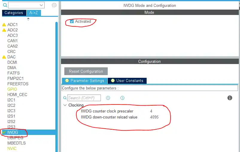
As you can see above, there are two parameters that we need to input i.e. the Prescalar and the Counter values. These values will decide the Reload time for our application. To decide these values, there is a formula provided by ST as shown below
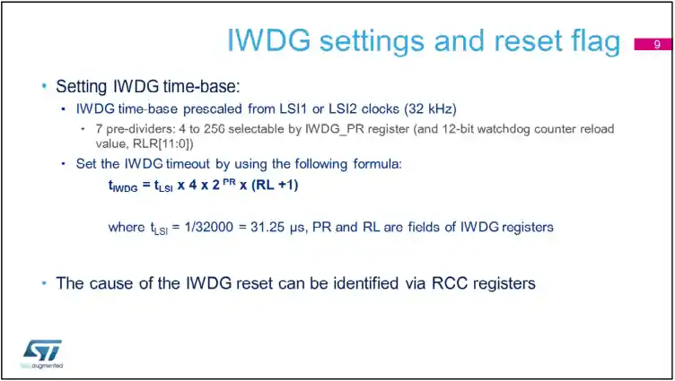
The original formula may seem a little confusing. I have simplified it, and the explanation of the terms used is provided below.
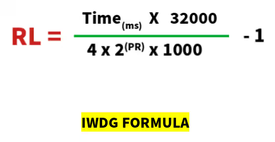
The terms used in the formula above is explained below:
- RL is the Counter value, that we need to put in the CubeMX Configuration.
- Time (in milliseconds) is the timeout value for the watchdog. If the counter is not refreshed before this time, the system will reset.
- PR refers to the prescaler, and its possible values are listed below.
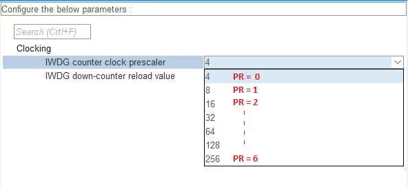
Let’s take an example, if i want to set the Timeout of 20 ms.
- I decided to choose the Prescalar as 8. So PR = 1
- If we substitute these values in the above formula, we will get the RL = 79.
- So we need to substitute counter value = 79 in our setup.
- If the RL value goes higher than 4095, then you need to increase the prescaler.
Step-by-Step Code Explanation
The code below shows how to implement the IWDG in STM32.
int main(void)
{

  HAL_Init();

  SystemClock_Config();

  MX_GPIO_Init();

  HAL_Delay (500);
  HAL_GPIO_WritePin(GPIOA, GPIO_PIN_5, 1);

  MX_IWDG_Init();

  while (1)
  {
    HAL_Delay (18);
    HAL_IWDG_Refresh(&hiwdg);

  }
}MX_IWDG_Init()Initializes the IWDG.- Note that I have turned on the LED before initializing the watchdog. If the system resets due to watchdog, the execution will starts from the beginning and this will act as LED blinking.
- Remember that the Timeout for the IWDG is set to 20ms during configuration. But as I am refreshing the counter after 18ms, the system will never reset, and the while loop will keep executing forever.
With this configuration, the LED will remain ON as the watchdog refreshes before timeout. You can check the video at the beginning of this post to see the working.
Common IWDG Configurations in STM32
- Prescaler (PR): Defines division factor for LSI clock.
- Reload Value (RL): Sets maximum timeout (0–4095).
- HAL_IWDG_Refresh(): Must be called before timeout.
Once enabled, IWDG cannot be disabled except by reset.
STM32 Window Watchdog (WWDG) – Setup & Example
The Window Watchdog (WWDG) is designed to detect software faults.
- It can be configured to identify application behavior that occurs either too late or too early.
- It is especially useful in applications that must respond within a precise timing window.
- Once the watchdog is enabled, it cannot be turned off except by performing a device reset.
In simple terms, the WWDG creates a time window during which the counter must be refreshed. If the refresh happens too early or too late, the watchdog triggers a system reset.
Window WatchDog (WWDG) Configuration
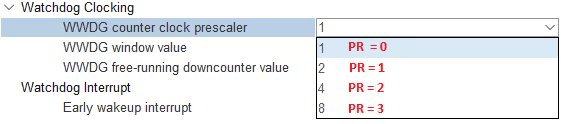
The STM32CubeMX configuration for the WWDG is shown below.

As shown above, we have 3 parameters to configure. They are prescalar, the window value, and the downcounter value.
Let’s first see the formula provided by ST to handle this.
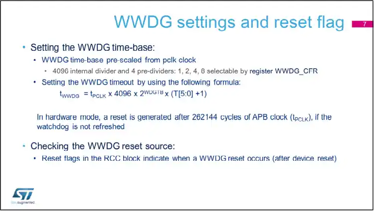
The original formula may seem a little confusing. I have simplified it, and the explanation of the terms used is provided below.
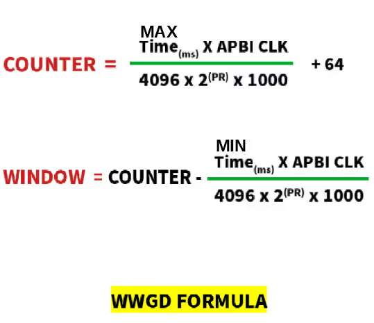
The terms used in the formula are explained below:
- WWDG is connected to the APB1 bus, and therefore derives it’s clock from APB1 CLOCK.
- COUNTER value is the value for downcounter.
- This value is related to the MAX TIME (in milliseconds) of the timeout window.
- WINDOW is the window value in the setup, and related to the MIN TIME (in milliseconds) of the timeout window.
- PR refers to the prescaler, and its possible values are listed below.
Let’s take an example, where I want the timeout window in between the 13ms – 20ms. To do this calculation, the steps are as provided below
- First, do the calculation for COUNTER value, as it is required to calculate WINDOW value.
- I am choosing the prescaler of 4, so the PR = 2
- After substituting the required values in the 1st formula, I got the COUNTER = 119. Here APB1 CLOCK = 45 MHz, and MAX TIME = 20
- Using this COUNTER value, and MIN TIME = 13, we can find the WINDOW value
- WINDOW = 83
- We need the substitute these values in our setup i.e. Prescalar = 4, Window = 83, and Downcounter = 119
- Keep in mind that the min and max values for Window and Downcounter are 64 and 127. So if you are getting the values higher or lower than these, you need to reduce or increase the prescalar respectively.
Step-by-Step Code Explanation
The code below shows how to implement the IWDG in STM32.
int main(void)
{

  HAL_Init();

  SystemClock_Config();

  MX_GPIO_Init();

  HAL_Delay (500);
  HAL_GPIO_WritePin(GPIOA, GPIO_PIN_5, 1);

  MX_WWDG_Init();

  while (1)
  {
    HAL_Delay (15);
    HAL_WWDG_Refresh (&hwwdg);
  }
}MX_WWDG_Init()Initializes the WWDG.- Note that I have turned on the LED before initializing the watchdog. If the system resets due to watchdog, the execution will starts from the beginning and this will act as LED blinking.
- Remember that the Timeout for the WWDG is set between 13ms – 20ms during configuration. But as I am refreshing the counter after 15ms, the system will never reset, and the while loop will keep executing forever.
With this configuration, the LED will remain ON as the watchdog refreshes before timeout. You can check the video at the beginning of this post to see the working.
One thing to keep in mind here is that, if I try to reset the counter in 10ms (<13ms) or 22ms (>20ms), the system will keep resetting and the LED will keep blinking.
IWDG vs WWDG – Key Differences
The Independent Watchdog (IWDG) and Window Watchdog (WWDG) work in different ways. Each has its own features, clock source, and use cases. The table below shows their key differences.
| Feature | IWDG (Independent Watchdog) | WWDG (Window Watchdog) |
|---|---|---|
| Clock Source | LSI (independent, low-speed internal oscillator) | APB1 (derived from system clock) |
| Refresh Flexibility | Can be refreshed anytime before timeout | Must be refreshed within a valid time window |
| Timing Precision | Less precise (depends on LSI accuracy) | More precise (synchronized with system clock) |
| Use Cases | Safety-critical, low-power, fault recovery | Precise timing detection, catching early/late refresh |
| Disable Option | Only via system reset | Only via system reset |
| Power Consumption | Low (uses LSI oscillator) | Slightly higher (uses system clock) |
| Complexity | Simple to configure and use | More complex due to timing window constraints |
| Independence | Independent of system clock (runs even if main clock fails) | Depends on system clock; stops if system clock fails |
| Reset Trigger | If not refreshed before timeout | If refreshed too early, too late, or not refreshed at all |
With this tutorial, you now understand how to use both IWDG and WWDG in STM32. The IWDG is simple and independent of the system clock, making it reliable in case of clock failures. The WWDG, on the other hand, provides finer control by enforcing refreshes within a timing window. We also saw how to calculate prescalers, reload values, and implement refresh functions like HAL_IWDG_Refresh and HAL_WWDG_Refresh. In upcoming guides, we’ll cover advanced topics such as interrupts with IWDG, disabling watchdogs for debugging, and STM32H7 watchdog examples.
PROJECT DOWNLOAD
Project FAQs


Great explanation!
The IWDG modified formula is wrong. it supposed to be,
RL = ((Time x 32000) / (4 * 2^PR)) – 1
Note, the formula for IWDG (RL calc) does not meet the times reported in document RM0090 for STM32F4.
I have tried running same program using different values of prescalar for same time but the leb neither glows nor blinks please upload more videos related to stm32
Thanks for this tutorial.
With my stm32f103c8t in the cubeIDE clockConfiguration module the LSI RC clock is 40kHz (not changeable). So that is the basis for my watchdog timing.
Just for information, that it is not automatically 32kHz to calculate with. Don’t know what influences the LSI RC speed, if it’s stm32 family dependent or something…
If you look at the second picture in the IWDG, it clearly defines the use of LSI.
Since the F103C8 have 40Khz, I guess instead of 32000, you should use 40000.
I haven’t tried it, but let me know the result.
Well, I use prescaler 128 and reload 4095. With 32kHz this should give me 16,4s watchdog timeout. With 40kHz it results in 13,1s timeout.
And what do I “measure” (with LED turning off and on and stop watch)? 14 seconds, which is more like 13s than 16s. But 1s difference is far beyond my reaction time.
Maybe the internal clock is not that precise, or something from the startup takes some time. I also tried with reduced prescaler, instead of calculated 6,5s I measure 7s and instead of 3,3s timeout I get 3,5s… so some proportional problem.
you are very good guy. thanks for sharing your knowledge.
Thanks again.
Great Work !