How to Interface Incremental Encoders with STM32 Using Timer Encoder Mode
Incremental encoders are widely used in robotics, automation, and motor control to precisely track the position and rotation of a shaft. Unlike absolute encoders, they don’t give a fixed position at startup but instead provide pulses that indicate movement and direction.
In this tutorial, we’ll explore how to interface an incremental encoder with an STM32 microcontroller using the Timer Encoder Mode – a hardware-based approach that eliminates the need for GPIO polling and provides reliable, accurate position tracking. Whether you’re a beginner or looking to refresh your knowledge, this guide walks you through both the concepts and practical implementation step by step.
What is an Incremental Encoder and How Does It Work?
An incremental encoder is a linear or rotary electromechanical device that has two output signals, A and B (sometimes labeled as CLK and DT), which issue pulses when the device is moved. Together, the A and B signals indicate both the occurrence of and direction of movement.
Unlike an absolute encoder, an incremental encoder does not indicate absolute position. It only reports changes in position, and for each reported position change, the direction of movement.
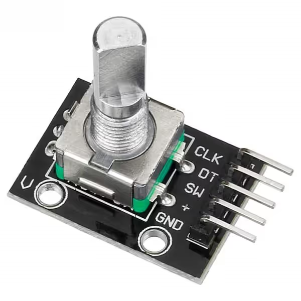
In the above picture, the CLK and DT are the two output signals that I was talking about. These will be considered as the A and B signals from the Encoder. To explain it more clearly, below is the GIF from the Wikipedia page
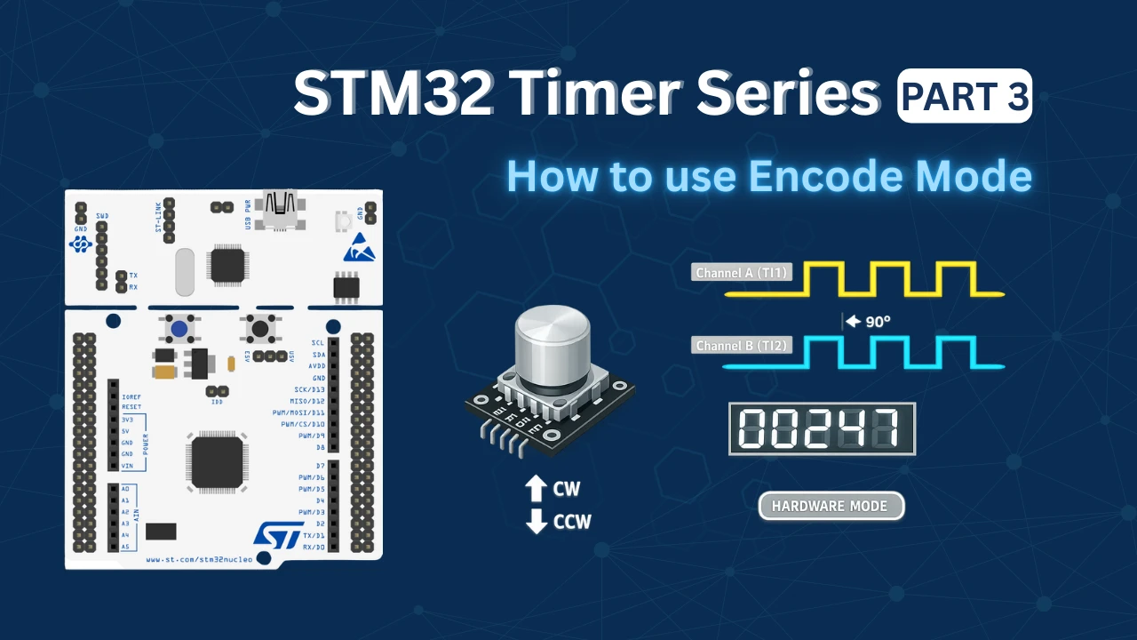
Understanding Quadrature Encoding
The two output signals A and B are 90 degrees out of phase with each other. This phase relationship is what allows us to determine the direction of rotation:
- Clockwise (CW) rotation: Channel A leads Channel B – when A transitions, B is still low
- Counter-Clockwise (CCW) rotation: Channel B leads Channel A – when A transitions, B is already high
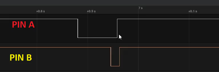
Here’s what the signals look like during rotation:
Clockwise Movement:
- Both signals start HIGH
- Channel A goes LOW first
- Channel B goes LOW after A
- Both go HIGH again
- The pattern repeats
Counter-Clockwise Movement:
- Both signals start HIGH
- Channel B goes LOW first
- Channel A goes LOW after B
- Both go HIGH again
- The pattern repeats

This 90-degree phase shift creates what’s called “quadrature encoding” – named after the four distinct states the two channels create during one complete cycle.
Why Use Timer Encoder Mode Instead of GPIO Polling?
The Old Approach: GPIO Polling
In a traditional GPIO polling approach, you would:
- Continuously check if Pin A is LOW
- When Pin A goes LOW, check the state of Pin B
- Determine direction based on whether Pin B was already LOW (CCW) or still HIGH (CW)
- Wait for pins to return HIGH
- Add delays to debounce
Problems with GPIO polling:
- CPU-intensive – constantly checking pin states in the main loop
- Easy to miss pulses at high rotation speeds
- Requires careful debouncing logic
- Blocking code that prevents other tasks from running
- Inconsistent counting at varying speeds
The Better Approach: Timer Encoder Mode
STM32 timers have a built-in Encoder Mode that uses hardware to:
- Automatically decode quadrature signals
- Count pulses in both directions
- Track direction without software intervention
- Never miss pulses (hardware-based)
- Free up the CPU for other tasks
- Provide consistent, accurate position tracking
The timer hardware handles everything automatically – you just read the counter value whenever you need the current position!
How STM32 Timer Encoder Mode Works
STM32 timers can be configured in encoder mode where:
- Channel 1 (TI1) connects to encoder signal A
- Channel 2 (TI2) connects to encoder signal B
- The timer’s counter register automatically increments/decrements based on the encoder signals
Encoder Mode Types
There are three encoder modes available:
- TI1 Mode (Encoder Mode 1): Counts only on Channel 1 edges based on Channel 2 level
- 1 count per pulse
- Less resolution but simple
- TI2 Mode (Encoder Mode 2): Counts only on Channel 2 edges based on Channel 1 level
- 1 count per pulse
- Less resolution but simple
- TI12 Mode (Encoder Mode 3): Counts on both Channel 1 and Channel 2 edges
- 2 counts per pulse (highest resolution)
- Most commonly used – provides 4x resolution
- Recommended for most applications
TI12 Mode gives you the best resolution because it counts on every edge (rising and falling) of both channels, effectively quadrupling your encoder’s native resolution.
How the Counter Updates
In TI12 mode, the timer counter:
- Increments when rotating in one direction
- Decrements when rotating in the opposite direction
- Updates on every edge of both channels A and B
- Provides 4 counts per encoder pulse cycle
The timing diagram below shows how STM32’s Timer Encoder Mode works in TI12 configuration.
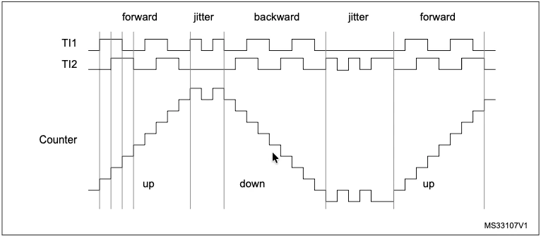
- TI1 and TI2 are the two encoder input channels (A and B signals)
- Forward rotation: TI1 leads TI2 (TI1 transitions first) → Counter increments
- Backward rotation: TI2 leads TI1 (TI2 transitions first) → Counter decrements
- Jitter sections: Show the encoder briefly reversing direction (common during start/stop or vibration)
- Counter waveform: Steps up during forward rotation, steps down during backward rotation
The hardware automatically detects which signal leads and counts up or down accordingly – counting on every edge of both channels for 4x resolution.
STM32CubeMX Configuration
Inside the cubeMX, I am going to configure the Timer 2 in the encoder mode. The image below shows the Timer configuration.
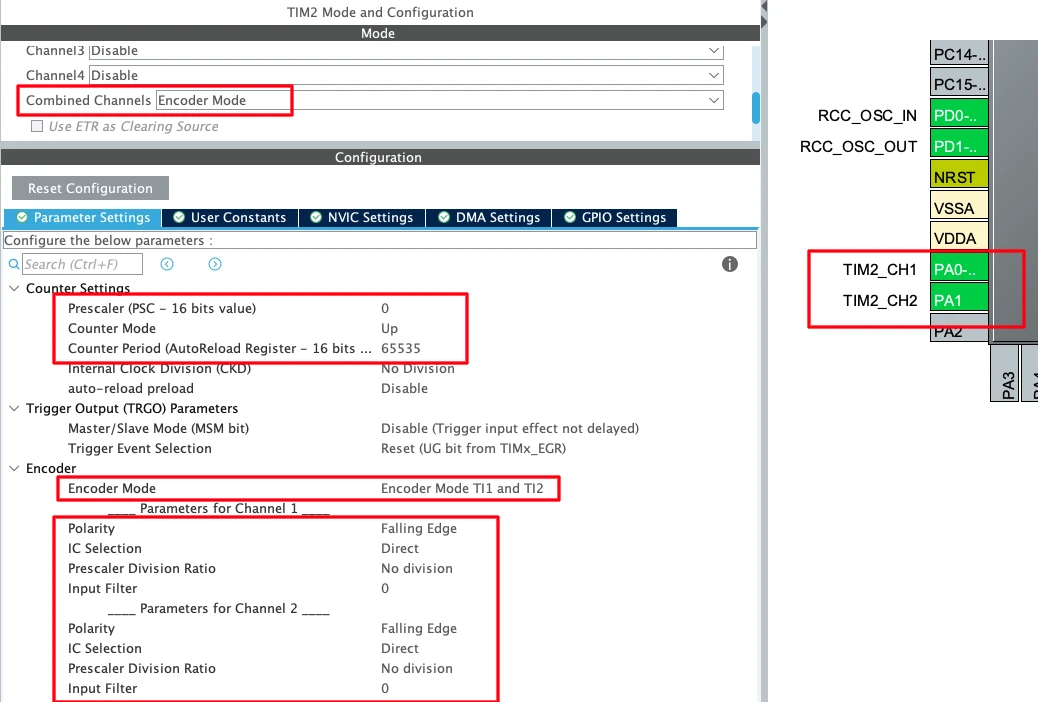
The pins PA0 and PA1 are automatically configured as the Timer encoder pins:
- PA0 → TIM2_CH1 (Encoder A)
- PA1 → TIM2_CH2 (Encoder B)
Configure the following parameters:
Encoder Settings:
- Encoder Mode: TI1 and TI2 (best resolution)
Counter Settings:
- Prescaler: 0 (no prescaling needed)
- Counter Period (ARR): 65535 (maximum for 16-bit timer)
- For 32-bit timers like TIM2 on some devices, you can use 0xFFFFFFFF
- Counter Mode: Up (though encoder mode overrides this)
- Auto-reload Preload: Disable
Input Capture Settings (for both channels):
- IC Polarity: Falling edge (or rising, based on your encoder)
- IC Selection: Direct TI
- IC Prescaler: No division
- IC Filter: 0 (or small value like 5-10 if you have electrical noise)
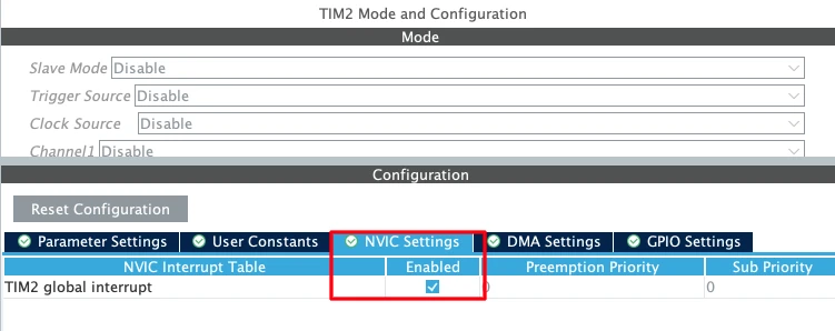
After configuring the parameters, go to the NVIC Tab and enable the interrupt as well.
HAL Code for the Timer Encoder Mode
In your main() function, after initialization, start the encoder:
int main(void)
{
  HAL_Init();
  SystemClock_Config();
  MX_GPIO_Init();
  MX_TIM2_Init();

  // Start encoder mode
  HAL_TIM_Encoder_Start_IT(&htim2, TIM_CHANNEL_ALL);

  while (1)
  {
    // Your code here
  }
}The encoder start function properly configures the channels for encoder mode.
Reading the Encoder Position
Once the pulse from the encoder is captured, an interrupt will trigger and the Input Capture Callback is called. We can read the counter inside this callback.
int16_t counter = 0;
int16_t count = 0;

void HAL_TIM_IC_CaptureCallback(TIM_HandleTypeDef *htim)
{
	counter = __HAL_TIM_GET_COUNTER(htim);
	count = count/4;
}Understanding count Values
With TI12 mode and a typical rotary encoder:
- Each “click” or “detent” you feel produces 4 counts (one complete quadrature cycle)
- A 20-pulse-per-revolution encoder produces 80 counts per revolution in TI12 mode
- A 600-pulse-per-revolution encoder produces 2400 counts per revolution in TI12 mode
To convert to actual position:
// For a 20 PPR encoder
float revolutions = count / 80.0f;
float degrees = count / 80.0f * 360.0f;

// For a 600 PPR encoder
float revolutions = count / 2400.0f;
float degrees = count / 2400.0f * 360.0f;Troubleshooting
Counter Not Changing
- Check pin connections (A to CH1, B to CH2)
- Verify encoder power supply
- Check that encoder mode is started with
HAL_TIM_Encoder_Start() - Confirm pins are properly configured in CubeMX as encoder inputs
Wrong Direction
- Swap encoder A and B connections, OR
- Change IC polarity from FALLING to RISING (or vice versa)
Counting Too Fast or Slow
- Verify encoder mode (should be TI12 for 4x resolution)
- Check encoder specifications (PPR rating)
- Remember: TI12 mode gives 4 counts per encoder pulse cycle
Erratic Counting
- Add input filtering (IC Filter parameter, try values 5-10)
- Check for electrical noise
- Ensure proper grounding
- Add pull-up resistors if encoder has open-collector outputs
- Check encoder power supply voltage
Counter Wrapping Issues
- Use signed integers (
int16_t) to properly handle negative values - For continuous tracking beyond 16-bit range, implement delta calculation as shown in examples
- Consider using a 32-bit timer (TIM2, TIM5) for larger range
VIDEO Tutorial
STM32 Timer Encoder Mode Tutorial Video
This tutorial explains how to interface rotary encoders with STM32 microcontrollers using Timer Encoder Mode. Along with the written guide, this video walks through the timer configuration in CubeMX, encoder mode setup, and the HAL code used to read position and direction from quadrature encoder signals. Watch the video to clearly understand how Timer Encoder Mode works at both the hardware and code level, and why it’s superior to GPIO polling methods.
Watch the VideoConclusion
Timer Encoder Mode represents one of the most elegant solutions in STM32’s peripheral library, transforming what could be a complex software problem into a simple hardware-based implementation. By leveraging the timer’s built-in quadrature decoder, you eliminate the need for polling loops, debouncing logic, and direction detection code. The hardware does all the heavy lifting – monitoring both encoder channels, automatically determining rotation direction, and maintaining an accurate position count even at high speeds. This not only frees up valuable CPU cycles for other tasks but also ensures you never miss a pulse, regardless of how fast the encoder rotates or how much your application code is doing.
Whether you’re building a robot that needs precise wheel odometry, a CNC machine requiring accurate position feedback, or a simple user interface with a rotary knob, Timer Encoder Mode provides a professional-grade solution with minimal code complexity. The ability to simply read a counter value and immediately know your position – without worrying about interrupt timing, debouncing, or missed edges – makes this feature invaluable for any embedded systems engineer. Once you experience the reliability and simplicity of hardware-based encoder reading, you’ll never want to go back to GPIO polling methods. Start experimenting with this powerful feature in your next STM32 project, and you’ll quickly appreciate why it’s the industry-standard approach for rotary encoder interfacing.
Checkout More STM32 Timer Tutorials
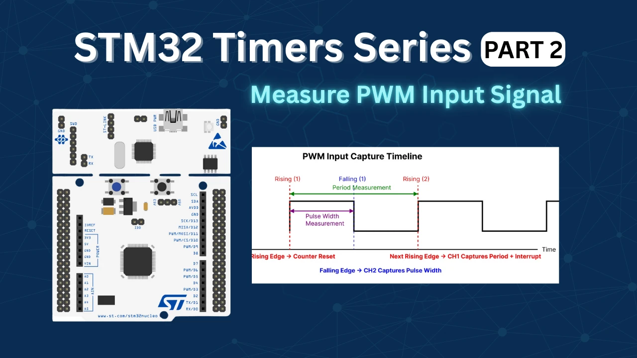
STM32 Timers (Part 2): How to Measure PWM Input Signal
STM32 Input Capture: Measure Frequency & Pulse Width
STM32 Timer Synchronization: Slave Trigger Mode with CubeMX & HAL
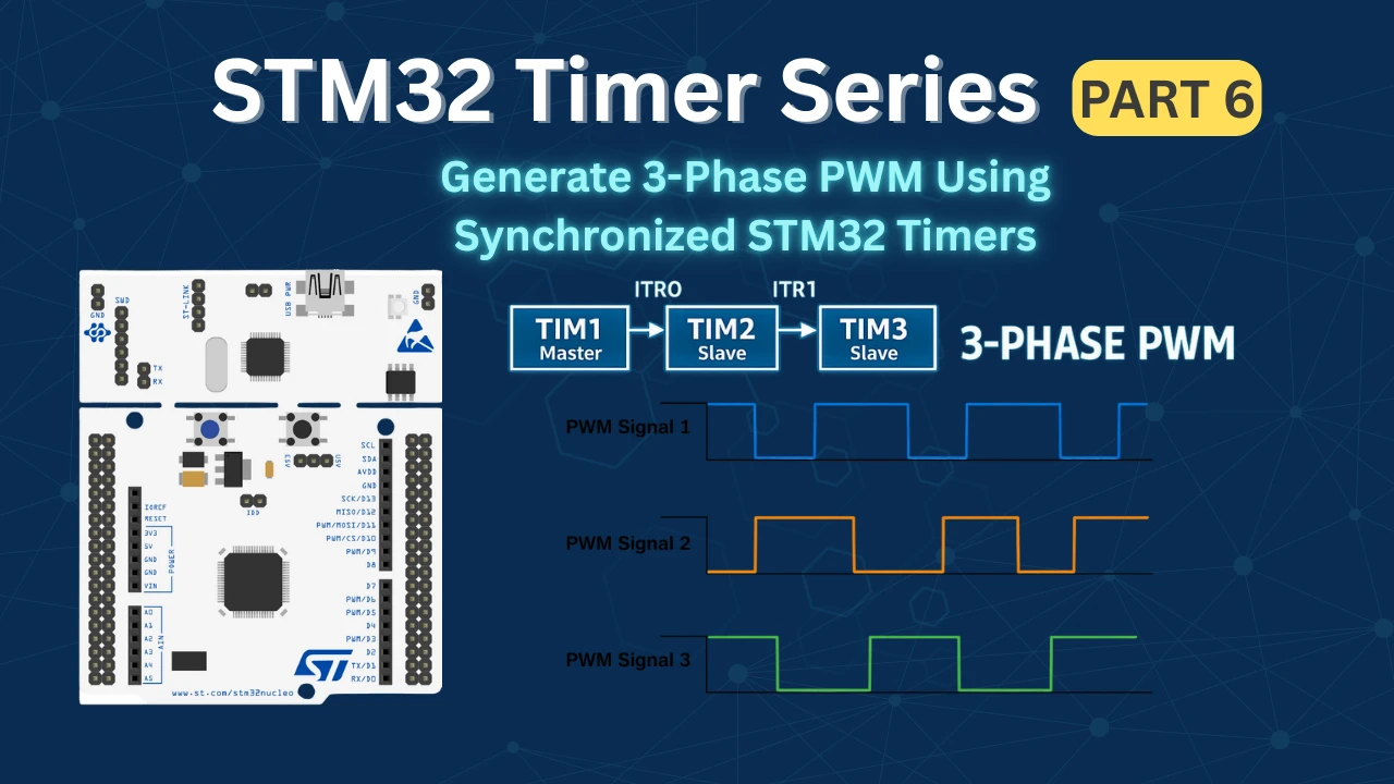
STM32 Timers (Part 6): Timer Synchronization for 3-Phase PWM Generation
STM32 Timers (Part 7): Timer synchronization using Slave Reset mode
STM32 Timers (Part 8): How to Create a 48-Bit Counter by Cascading Timers
STM32 Timers (Part 9): One Pulse Mode (OPM) – Generate Precise Triggered Pulses with Delay and Width Control
STM32 Encoder Mode Project Download
STM32 Encoder Mode FAQs

Subscribe
Login
0 Comments
Newest
