How to use input button in AVR (xplained mini)
This is the 2nd tutorial in the AVR series using the xplained mini microcontroller board and today we will see how to use the input button. We will interface the physical button with and without the interrupt. Also we will use this button to control the LED on board, which we interfaced in the previous tutorial.
The xplained mini already has a button soldered onto the board. Below is the image showing the button.
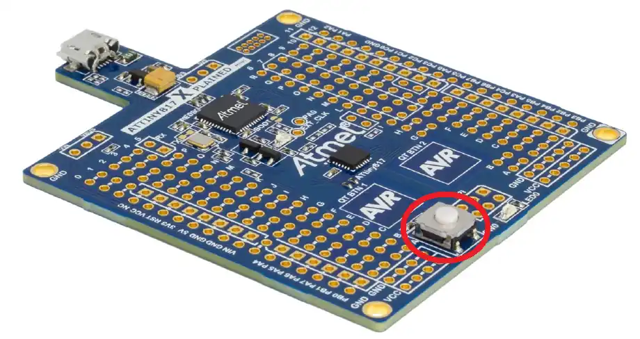
The image below shows the schematic of the button.
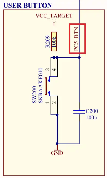
As shown above, the pin PC5 is connected to the VCC and the button. By default, when the button is released, the pin PC5 is pulled up to the VCC. Pressing the button pulls the pin LOW to the ground. We will use this logic to write the code.
VIDEO TUTORIAL
You can check the video to see the complete explanation and working of this project.
Without Interrupt
We will use the clock setup from the previous tutorial.
#define F_CPU 5000000
#include <xc.h>
#include <util/delay.h>
#include <avr/interrupt.h>

void clkInit(void)
{
	_PROTECTED_WRITE(CLKCTRL.MCLKCTRLA, 0);  // Internal 20MHz OSC, CLKOUT=0
	_PROTECTED_WRITE(CLKCTRL.MCLKCTRLB, 0x03);  // PEN=1, DIV=4
	while ((CLKCTRL.MCLKSTATUS & (1<<4)) == 0);  // wait for the osc to stabilize.
}

int main(void)
{
	clkInit();
}This is already explained in the previous tutorial, so I will skip it here.
The Direction Register (DIR) is used to set the pin input or output. The button is connected to the pin PC5 and the LED is connected to the pin PC0. Therefore we need to set the pin PC5 as input and the pin PC0 as output.
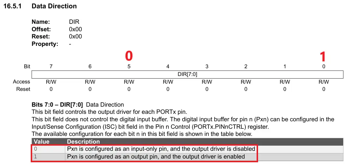
PORTC.DIR = 0x01; // PC5->input, PC0->outputHere I have set the PORTC Direction register to 0x01. This sets the PC5 as input and PC0 as output.
We will read the button state in the while loop. The INPUT Register can be used to read the state of the pin.
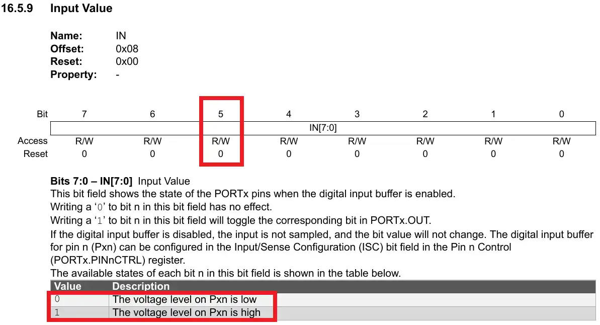
The pin PC5 is pulled up to the VCC and when the button is pressed, it will be pulled LOW to the ground. We will basically monitor the bit 5 of the INPUT Register in the while loop.
  while(1)
  {
	  if ((PORTC.IN & (1<<5)) == 0)
	  {
		  PORTC.OUT |= (1<<0);  // turn the LED ON
		  while ((PORTC.IN & (1<<5)) == 0);  // wait for the button to release
	  }
	  PORTC.OUT &= ~(1<<0);
	  _delay_ms(500);
}- When the button is pressed, the pin PC5 goes low. This is where we will turn the LED ON.
- Then we will wait for the button to be released and the pin PC5 to go HIGH again.
- Once the button is released, we will turn the LED OFF.
Basically the LED will turn ON when the button is pressed, and it will remain ON as long as the button is pressed. It will turn OFF when the button is released.
The gif below shows the working on the xplained mini.

With Interrupt
The Pin n Control Register (PINnCTRL) can be used to enable the External Interrupt for the Respective pin.
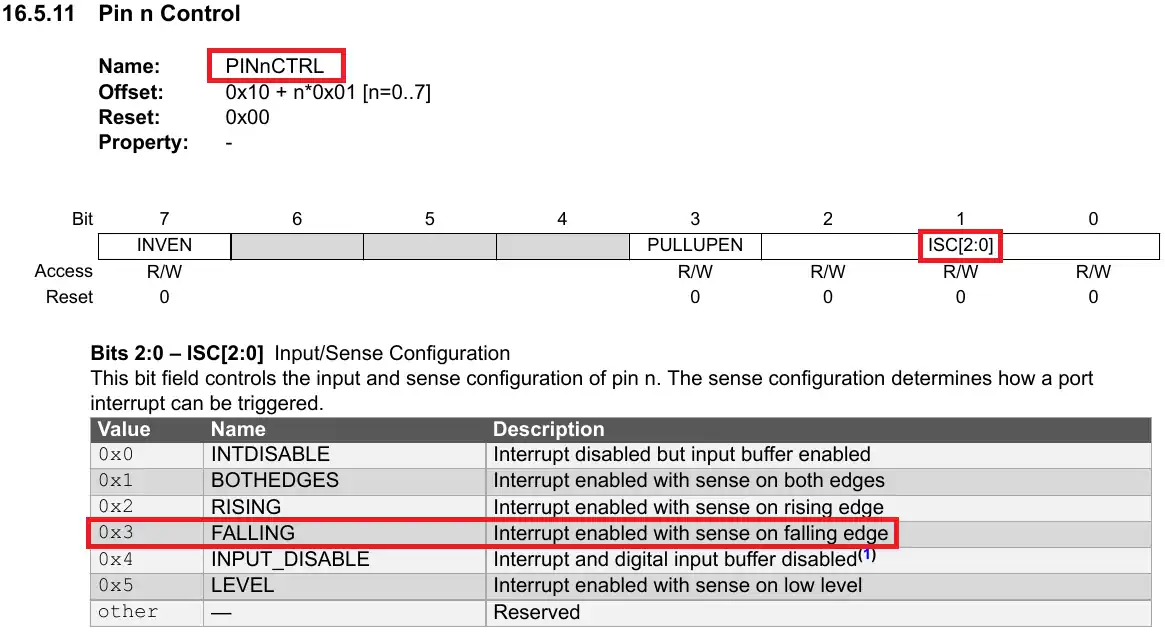
The Bits [2:0] of this Register are used for the Input/Sense configuration. We can set the Interrupt to trigger for the Rising edge, falling edge or both the edges.
I am going to configure the interrupt for the falling edge, so the interrupt will Trigger as soon as the button is pressed.
	PORTC.DIR = 0x01;  // PC5->input, PC0->output
	PORTC.PIN5CTRL |= 0x2;  // falling sense
sei();Here after setting the direction of the pins, I have configured the falling edge interrupt trigger for the pin PC5. then the function sei() is used to enable the global interrupt.
The pin PC5 is in the HIGH state by default. Once the button is pressed, the pin will be pulled LOW to the ground and the interrupt will trigger for the falling edge.
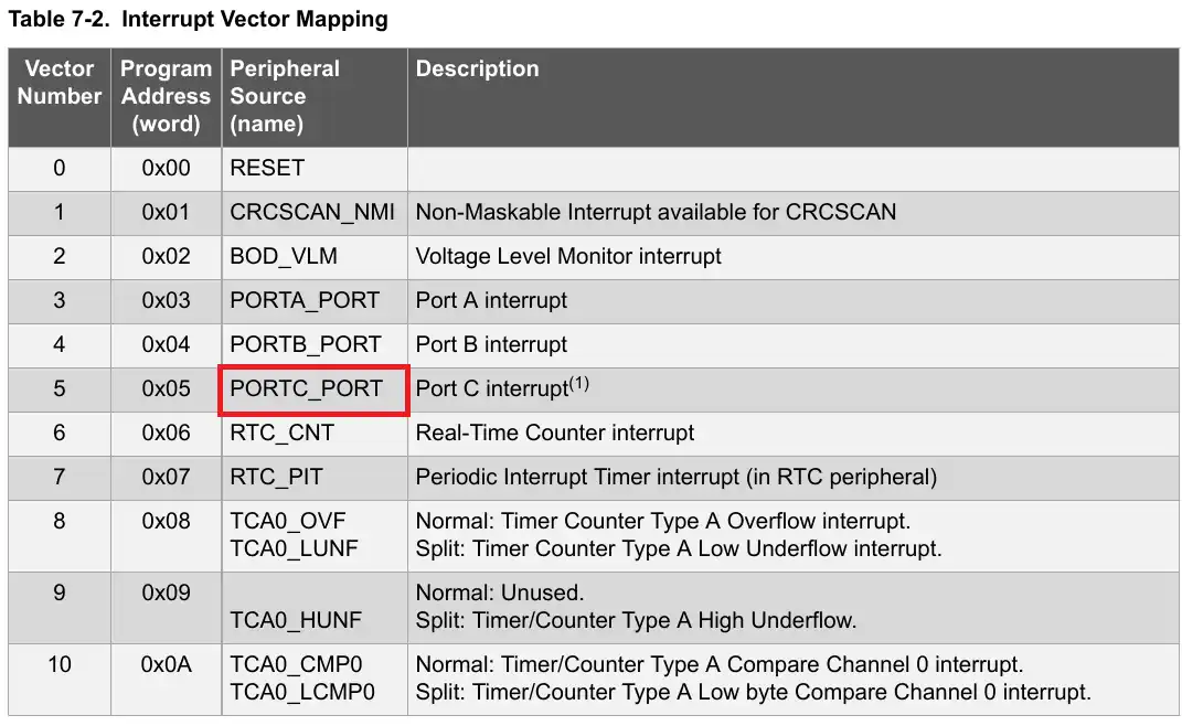
We will write an Interrupt Service Routine (ISR) to handle this interrupt. The parameter of the ISR should be the interrupt vector, which needs to be handled.
You can find the respective Interrupt vector in the device datasheet as shown below.
The interrupt Flags Register (INTFLAGS) can be used to check and clear the respective external interrupt.
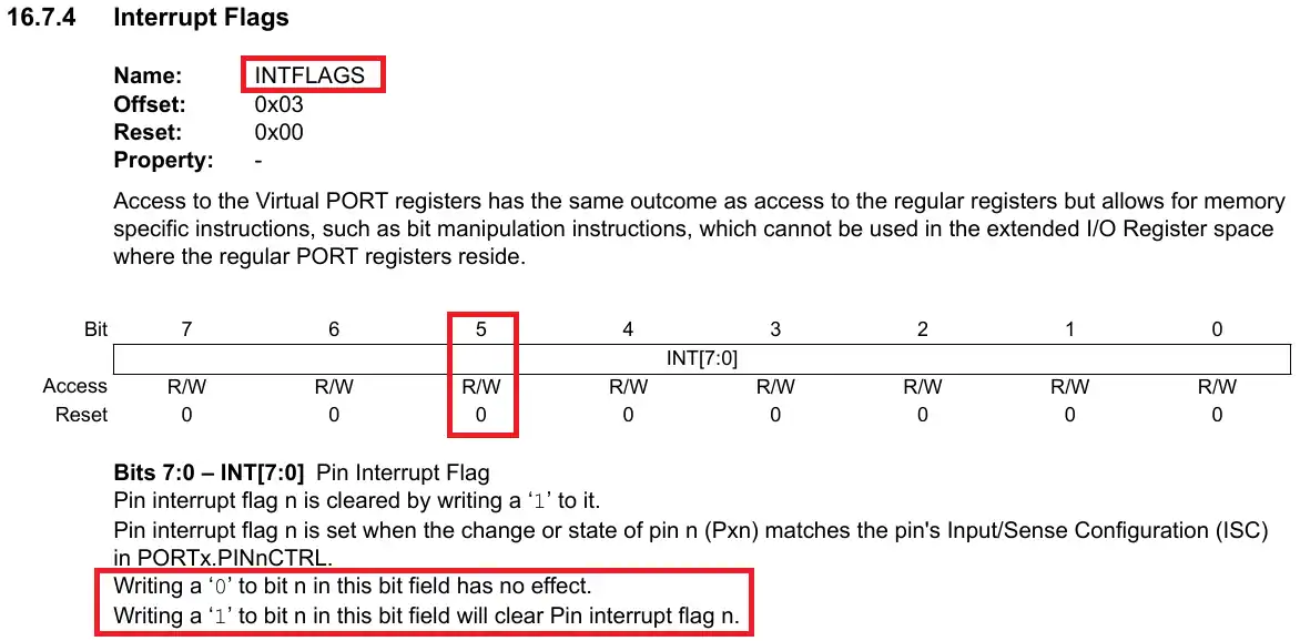
We will use this register to first check if the interrupt is triggered by the pin PC5, and then use it to clear the interrupt flag.
ISR(PORTC_PORT_vect)
{
	uint8_t flag = PORTC.INTFLAGS;
	if (((flag>>5)&0x01) == 1)  // if the interrupt is triggered by the pin PC5
	{
		PORTC.OUTTGL = (1<<0);  // toggle the LED
		PORTC.INTFLAGS |= (1<<5);  // clear the interrupt flag
	}

}Inside the ISR we will check if the interrupt is triggered by the pin PC5. We will check this by monitoring the 5th bit of the INTFLAGS Register.
If the interrupt is triggered by PC5, we will toggle the LED and then clear the interrupt flag by writing a 1 to the 5th bit of the INTFLAGS Register.
Below is the gif showing the result of the interrupt code.


