
Home ▸ STM32 Tutorials ▸
Updated On: April 30, 2026
STM32 Low Power Modes: Sleep, Stop & Standby Explained
Battery life and power budget are what separate a working prototype from a shippable product. STM32 microcontrollers give you three hardware low-power modes — Sleep, Stop, and Standby — covering a range from a few milliamps down to 2 µA, with different trade-offs in wake-up speed, peripheral availability, and memory retention.
This guide covers all three modes with complete HAL code, real wake-up examples (EXTI, UART, RTC timer, wake-up pin), and measured power consumption on the STM32F103 Blue Pill. Each mode has its own section with a dedicated video — scroll to the mode you need or read through in order to understand when to use each one.
STM32 supports the following three low-power modes:
- Sleep Mode – The CPU (including the FPU core) is halted, while all peripherals continue to operate.
- Stop Mode – All internal clocks are halted, significantly reducing power usage while retaining RAM and register contents.
- Standby Mode – The 1.2V domain is powered off, resulting in the lowest power consumption. Most internal state is lost except for data retained in Backup SRAM or powered by VBAT.
STM32 Low Power Modes: Overview & Comparison
STM32 microcontrollers are designed with energy efficiency in mind, offering several low power modes to minimize current consumption during idle or inactive periods. These modes allow developers to optimize power usage depending on the application’s requirements, particularly in battery-powered or energy-sensitive systems.
Sleep, Stop & Standby at a Glance
The three main low power modes available in STM32 are:
- Sleep Mode
In Sleep mode, the CPU is halted while all peripheral clocks continue to run. This allows peripherals like timers, USART, or ADCs to remain active, enabling the MCU to quickly resume operation on an interrupt. It’s ideal for short, low-latency power-saving scenarios. - Stop Mode
Stop mode offers deeper power savings by disabling all clocks, including the system clock, while retaining the contents of RAM and registers. The regulator can be set in either main or low-power mode, and the MCU can be awakened through external interrupts, RTC, or other events. This mode is well-suited for applications with periodic wake-up requirements. - Standby Mode
Standby mode provides the lowest power consumption. In this mode, the 1.2V domain is powered off, most peripherals and internal memory are lost (except for data in Backup SRAM or RTC powered by VBAT). The MCU resumes from a reset after wake-up. This mode is ideal for ultra-low-power applications where the device remains off for extended periods.
Power Consumption Comparison (STM32F103)
The power savings in STM32 depend on the selected mode and voltage regulator settings. Here’s a rough comparison for STM32F103 (Blue Pill) at 3.3V supply:
| Mode | Current Draw (typical) | Wake-up Time | Retains RAM? | Use Case |
| Sleep | ~2–5 mA | Fast | Yes | Short idle time, timer active |
| Stop | ~20–100 µA | Medium | Yes | Periodic wake, sensor sleep |
| Standby | ~1–5 µA | Slow | No | Battery-powered deep sleep apps |
You can measure this using an ammeter in series with VDD or use ST-Link power monitor in STM32CubeIDE.
Feature Comparison Table
he table below compares the Sleep Mode, Stop Mode and Standby Mode.
| Feature / Mode | Sleep Mode | Stop Mode | Standby Mode |
|---|---|---|---|
| CPU | Stopped | Stopped | Powered off |
| Regulator | ON | Main OFF, Low-power ON | OFF |
| Clocks | Running (unless disabled manually) | HSI/HSE/PLL OFF, RTC/LSI/LSE can stay ON | All OFF except LSI/LSE if RTC enabled |
| SRAM / Registers | Retained | Retained | Lost (except Backup domain + RTC) |
| Wake-up sources | Any interrupt | EXTI, RTC, IWDG | Wakeup pin, RTC, NRST, IWDG |
| Wake-up time | Very short | Moderate | Long (reset sequence) |
| Power consumption | Lowest savings | Medium savings | Ultra-low (lowest) |
| Reset after wake-up | No | No | Yes (similar to Power-On Reset) |
Use Sleep for short idle periods, Stop for moderate low-power with quick resume, and Standby for maximum power saving when the MCU can afford a full reset on wake-up.
STM32 Sleep Mode: Enter, Wake Up & SLEEPONEXIT
I will first start with the simplest one, which is the SLEEP MODE. In this mode, CPU CLK is turned OFF and there is no effect on other clocks or analog clock sources. The current consumption is HIGHEST in this mode, compared to other Low Power Modes.
Entering Sleep Mode
To enter Sleep mode, we first need to disable the SysTick interrupt. Otherwise, the periodic SysTick will keep waking up the MCU.
HAL_SuspendTick(); // Disable the SysTick interruptNext, we can put the MCU into Sleep mode using either the WFI (Wait For Interrupt) or WFE (Wait For Event) instruction. If WFI is used, any peripheral interrupt acknowledged by the NVIC can wake the device.
HAL_PWR_EnterSLEEPMode(PWR_MAINREGULATOR_ON, PWR_SLEEPENTRY_WFI);Wake-up from Sleep Mode
Since we entered Sleep mode using WFI, the MCU will wake up whenever any interrupt is triggered. For example, if a GPIO external interrupt occurs:
void HAL_GPIO_EXTI_Callback(uint16_t GPIO_Pin)
{
    HAL_ResumeTick();  // Re-enable SysTick after wake-up
}Inside the interrupt callback, we resume the SysTick so that delay functions and other time-based operations work normally after waking up.
Using SLEEPONEXIT
STM32 also provides a feature called SLEEPONEXIT, which allows the MCU to automatically re-enter Sleep mode after servicing an interrupt. This means:
- The MCU wakes up when an interrupt occurs.
- It executes the corresponding ISR (Interrupt Service Routine).
- When the ISR exits, instead of returning to the main loop, the MCU goes back to Sleep mode immediately.
This is very useful in event-driven applications, where the CPU only needs to wake up to handle interrupts and doesn’t need to run background tasks in the main loop.
To enable this feature, call:
HAL_PWR_EnableSleepOnExit();And to disable it later, use:
HAL_PWR_DisableSleepOnExit();
Note:
Be careful when using SLEEPONEXIT — if your main loop is empty, the MCU may never return to it. This feature is best suited for interrupt-only applications such as ultra-low-power sensor nodes.
Full Sleep Mode Code Example
The entire code for the SLEEP MODE, with SLEEPONEXIT feature is shown below
uint8_t Rx_data;

// SleepOnExit will be applicable when the MCU is wake up by UART
void HAL_UART_RxCpltCallback(UART_HandleTypeDef *huart)
{
    HAL_UART_Receive_IT(huart, &Rx_data, 1);
    str = "WakeUP from SLEEP by UART\r\n";
    HAL_UART_Transmit(&huart2, (uint8_t *)str, strlen (str), HAL_MAX_DELAY);
}

// SleepOnExit will be disabled when the MCU is wake up by EXTI
void HAL_GPIO_EXTI_Callback(uint16_t GPIO_Pin)
{
    str = "WakeUP from SLEEP by EXTI\r\n";
    HAL_UART_Transmit(&huart2, (uint8_t *)str, strlen (str), HAL_MAX_DELAY);
    HAL_PWR_DisableSleepOnExit ();
}


int main ()
{
 ......
 ......
 HAL_UART_Receive_IT(&huart2, &Rx_data, 1);
 while (1)
  {

	  str = "Going into SLEEP MODE in 5 seconds\r\n";
	  HAL_UART_Transmit(&huart2, (uint8_t *)str, strlen (str), HAL_MAX_DELAY);

	  HAL_GPIO_WritePin(GPIOA, GPIO_PIN_5, 1);
  	  HAL_Delay(5000);

/*    Suspend Tick increment to prevent wakeup by Systick interrupt.
	  Otherwise the Systick interrupt will wake up the device within 1ms (HAL time base)
*/
	  HAL_SuspendTick();

	  HAL_GPIO_WritePin(GPIOA, GPIO_PIN_5, 0);  // Just to indicate that the sleep mode is activated

	  HAL_PWR_EnableSleepOnExit ();

//	  Enter Sleep Mode , wake up is done once User push-button is pressed
	  HAL_PWR_EnterSLEEPMode(PWR_MAINREGULATOR_ON, PWR_SLEEPENTRY_WFI);


//	  Resume Tick interrupt if disabled prior to sleep mode entry
	  HAL_ResumeTick();

	  str = "WakeUP from SLEEP\r\n";
	  HAL_UART_Transmit(&huart2, (uint8_t *)str, strlen (str), HAL_MAX_DELAY);

	  for (int i=0; i<20; i++)
	  {
		  HAL_GPIO_TogglePin(GPIOA, GPIO_PIN_5);
		  HAL_Delay(100);
	  }
  }
}Sleep Mode Result
The image below shows the MCU entering and waking up from the Sleep Mode
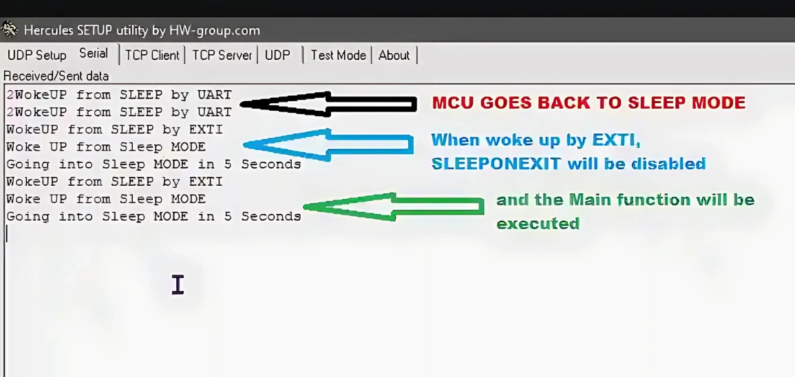
The first Black arrow in the image indicates that when the MCU wakes up because of the UART interrupt, it goes back to sleep after processing the ISR (i.e after printing the string). This shows that the SLEEPONEXIT is working well. The MCU servers the ISR and goes back to sleep, it does not enter the main function at all.
The Blue and Green arrows indicates that when the MCU wakes up because of the EXTI interrupt the SLEEPONEXIT is disabled, and rest of the main function is executed as usual.
STM32 Sleep Mode — Video Tutorial
This video demonstrates STM32 Sleep mode in practice — entering Sleep using HAL_PWR_EnterSLEEPMode(), suspending SysTick to prevent unwanted wake-ups, using SLEEPONEXIT to return to sleep after each ISR, and waking via UART and EXTI interrupts with live current measurement on the Blue Pill.
STM32 Stop Mode: Enter, Wake Up & RTC Timer
Stop mode provides deeper power savings compared to Sleep mode. In Stop mode, the main regulator is turned off, and only the low-power regulator remains active. This allows the MCU to retain SRAM and register contents while drastically reducing current consumption.
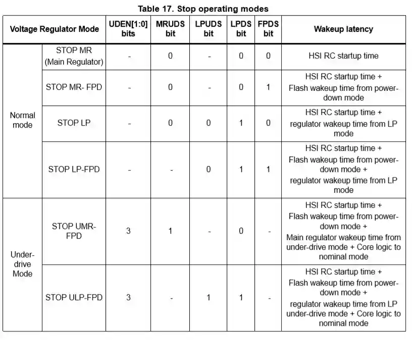
In Stop mode, all clocks in the 1.2 V domain are stopped, the PLLs, the HSI and the HSE RC oscillators are disabled. Internal SRAM and register contents are preserved. STOP MODE have may different categories depending on what should be turned off. Below is the picture from the STM32F446RE reference manual
Entering the Stop Mode
Just like in Sleep mode, we must first disable the SysTick interrupt to prevent it from waking the MCU:
HAL_SuspendTick(); // Disable SysTick to avoid unwanted wake-upsNext, the MCU is placed into Stop mode using either WFI (Wait For Interrupt) or WFE (Wait For Event).
- WFI: Wakes the MCU on any interrupt triggered by EXTI, RTC, or IWDG.
- WFE: Wakes the MCU on an event.
Example using WFI with the low-power regulator enabled:
HAL_PWR_EnterSTOPMode(PWR_LOWPOWERREGULATOR_ON, PWR_STOPENTRY_WFI);Wake-up from Stop Mode
When entering Stop mode with WFI, the MCU can wake up from:
- External interrupts (EXTI)
- Independent Watchdog (IWDG)
- RTC alarms or wake-up events
After waking up, the system clocks are not automatically restored. Therefore, you must:
- Reconfigure the system clock.
- Resume the SysTick interrupt.
Example:
void HAL_GPIO_EXTI_Callback(uint16_t GPIO_Pin)
{
    if (GPIO_Pin == GPIO_PIN_13)  // Example: wake-up by button on pin 13
    {
        SystemClock_Config();  // Reconfigure system clocks
        HAL_ResumeTick();      // Resume SysTick
    }
}
Note:
Forgetting to reconfigure the clock will result in unexpected behavior since peripherals and core clock may remain uninitialized after wake-up.
Using SLEEPONEXIT in Stop Mode
The SLEEPONEXIT feature works the same way in Stop mode as it does in Sleep mode:
- MCU wakes up on an interrupt.
- Executes the ISR.
- Immediately goes back to Stop mode once the ISR exits.
This is useful in event-driven applications where the MCU should stay in Stop mode until an interrupt occurs, without returning to the main loop.
Enable with:
HAL_PWR_EnableSleepOnExit();Disable with:
HAL_PWR_DisableSleepOnExit();Full Stop Mode Code Example
The entire code for STOP MODE is as shown below
// SleepOnExit will be applicable when the MCU is wake up by RTC
void HAL_RTCEx_WakeUpTimerEventCallback(RTC_HandleTypeDef *hrtc)
{
	SystemClock_Config ();
	HAL_ResumeTick();
	char *str = "WAKEUP FROM RTC\n NOW GOING IN STOP MODE AGAIN\n\n";
	HAL_UART_Transmit(&huart2, (uint8_t *) str, strlen (str), HAL_MAX_DELAY);

}

// SleepOnExit will be disabled when the MCU is wake up by EXTI
void HAL_GPIO_EXTI_Callback(uint16_t GPIO_Pin)
{
  if(GPIO_Pin == GPIO_PIN_13)
  {
	  SystemClock_Config ();
	  HAL_ResumeTick();
	  char *str = "WAKEUP FROM EXTII\n\n";
	  HAL_UART_Transmit(&huart2, (uint8_t *) str, strlen (str), HAL_MAX_DELAY);
	  HAL_PWR_DisableSleepOnExit();
  }
}

int main ()
{
 .......
 .......
 .......
  /*## Configure the Wake up timer ###########################################*/
  /*  RTC Wake-up Interrupt Generation:
      Wake-up Time Base = (RTC_WAKEUPCLOCK_RTCCLK_DIV /(LSI))
      ==> WakeUpCounter = Wake-up Time / Wake-up Time Base

      To configure the wake up timer to 20s the WakeUpCounter is set to 0xA017:
        RTC_WAKEUPCLOCK_RTCCLK_DIV = RTCCLK_Div16 = 16
        Wake-up Time Base = 16 /(32KHz) = 0.0005 seconds
        ==> WakeUpCounter = ~10s/0.0005s = 20000 = 0x4E20 */

  HAL_RTCEx_SetWakeUpTimer_IT(&hrtc, 0x4E20, RTC_WAKEUPCLOCK_RTCCLK_DIV16);


  /****** Suspend the Ticks before entering the STOP mode or else this can wake the device up **********/
  HAL_SuspendTick();

  HAL_PWR_EnableSleepOnExit();

  /* Enter Stop Mode */
  HAL_PWR_EnterSTOPMode(PWR_LOWPOWERREGULATOR_ON, PWR_STOPENTRY_WFI);


  HAL_RTCEx_DeactivateWakeUpTimer(&hrtc);

  for (int i=0; i<10; i++)
  {
  	  HAL_GPIO_TogglePin(GPIOA, GPIO_PIN_5);
  	  HAL_Delay(1000);
  }

 while (1)
  {
    .....
  }
}In this example, the STM32 is put into Stop mode with two wake-up sources:
- RTC Wake-up Timer → wakes the MCU periodically (every ~10 seconds in this case).
- External Interrupt (GPIO pin 13) → wakes the MCU when the button is pressed.
Key parts of the code:
HAL_RTCEx_WakeUpTimerEventCallback()
Runs when the RTC wake-up timer expires. The system clock and SysTick are reconfigured, then a message is sent over UART. After handling the event, the MCU goes back into Stop mode automatically (becauseHAL_PWR_EnableSleepOnExit()was enabled).HAL_GPIO_EXTI_Callback()
Runs when the external button (pin 13) is pressed. Like the RTC case, it reconfigures the system clock, resumes SysTick, and sends a UART message.
Additionally, it callsHAL_PWR_DisableSleepOnExit();to stop automatically returning to Stop mode — this lets the main program continue execution.main()setup- Configures RTC wake-up timer for ~10 seconds (
0x4E20with LSI/16). - Suspends SysTick to avoid unwanted wake-ups.
- Enables
SLEEPONEXITso the MCU automatically re-enters Stop mode after ISR handling. - Enters Stop mode with low-power regulator.
- Configures RTC wake-up timer for ~10 seconds (
After exiting Stop mode and disabling the wake-up timer, the code toggles an LED 10 times with a delay, then continues into the infinite loop.
Stop Mode Result
The RTC Setup is very long, and it is explained in the Video. Do check the video below to understand it.
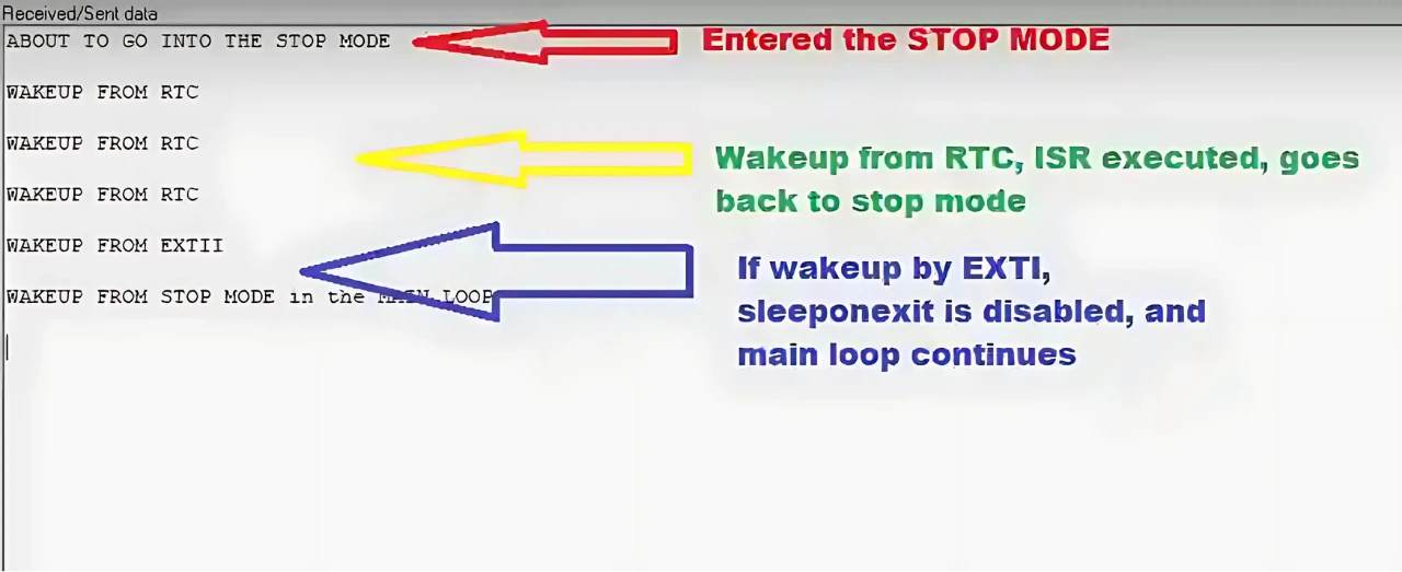
The First Red arrows indicates that the MCU is going in the STOP Mode.
The Yellow arrow indicates that when the MCU wakes-up due to the RTC interrupt, the corresponding ISR is executed and the MCU goes back to STOP mode. This implies that the SLEEPONEXIT is working fine.
The Blue arrow indicates that when the MCU wakes-up due to the EXTI interrupt, the corresponding ISR is executed and it continue with the main loop. This is because we are disabling the SLEEPONEXIT inside this ISR, hence the MCU can not enter the STOP mode automatically again.
STM32 Stop Mode — Video Tutorial
This video covers STM32 Stop mode setup — entering Stop with HAL_PWR_EnterSTOPMode(), configuring the RTC wake-up timer, reconfiguring the system clock after wake-up, SLEEPONEXIT behaviour with RTC and EXTI sources, and live current consumption measurement on the Blue Pill.
STM32 Standby Mode: Lowest Power & Reset on Wake
Standby mode achieves the lowest power consumption on STM32 MCUs. In this mode:
- The voltage regulator is disabled, powering down the 1.2 V domain.
- The PLLs, HSI, and HSE oscillators are turned off.
- Only the contents of the backup registers, RTC, and standby circuitry are retained.
This mode is based on the Cortex-M4 deep-sleep state and is ideal for ultra-low-power applications where the device spends most of its time idle and only wakes up occasionally.
Entering Standby Mode
Before entering Standby mode, you must clear wake-up flags to avoid accidental wake-ups:
/* Clear wake-up flag */
__HAL_PWR_CLEAR_FLAG(PWR_FLAG_WU);

/* Clear RTC wake-up flag */
__HAL_RTC_WAKEUPTIMER_CLEAR_FLAG(&hrtc, RTC_FLAG_WUTF);Next, configure the wake-up source — this can be a wake-up pin (e.g., PA0) or an RTC wake-up timer.
Example: enabling both wake-up pin and RTC timer (5 seconds):
/* Enable wake-up pin */
HAL_PWR_EnableWakeUpPin(PWR_WAKEUP_PIN1);

/* Configure RTC wake-up timer for ~5s */
if (HAL_RTCEx_SetWakeUpTimer_IT(&hrtc, 0x2710, RTC_WAKEUPCLOCK_RTCCLK_DIV16) != HAL_OK)
{
    Error_Handler();
}Finally, enter Standby mode:
HAL_PWR_EnterSTANDBYMode();Wake-up from Standby Mode
Waking from Standby mode is equivalent to a system reset:
- The code starts from the reset vector (like after power-on or hardware reset).
- The only indication of a Standby wake-up is the SBF flag in the PWR_CSR register.
Possible wake-up sources include:
- Rising edge on a wake-up pin (WKUP)
- RTC alarm (A or B) or RTC wake-up event
- Tamper or timestamp event
- NRST pin reset
- Independent watchdog (IWDG)
Full Standby Mode Code Example
The following program demonstrates entering and waking from Standby mode with RTC + wake-up pin:
int main(void)
{
    ...

    /* Check if waking from Standby */
    if (__HAL_PWR_GET_FLAG(PWR_FLAG_SB) != RESET)
    {
        __HAL_PWR_CLEAR_FLAG(PWR_FLAG_SB);  // Clear flag

        char *str = "Wakeup from STANDBY MODE\n\n";
        HAL_UART_Transmit(&huart2, (uint8_t *)str, strlen(str), HAL_MAX_DELAY);

        /* Blink LED */
        for (int i = 0; i < 20; i++)
        {
            HAL_GPIO_TogglePin(GPIOA, GPIO_PIN_5);
            HAL_Delay(200);
        }

        /* Disable wake-up pin and RTC wake-up */
        HAL_PWR_DisableWakeUpPin(PWR_WAKEUP_PIN1);
        HAL_RTCEx_DeactivateWakeUpTimer(&hrtc);
    }

    /* Prepare for Standby */
    __HAL_PWR_CLEAR_FLAG(PWR_FLAG_WU);
    __HAL_RTC_WAKEUPTIMER_CLEAR_FLAG(&hrtc, RTC_FLAG_WUTF);

    char *str = "About to enter STANDBY MODE\n\n";
    HAL_UART_Transmit(&huart2, (uint8_t *)str, strlen(str), HAL_MAX_DELAY);

    for (int i = 0; i < 5; i++)
    {
        HAL_GPIO_TogglePin(GPIOA, GPIO_PIN_5);
        HAL_Delay(750);
    }

    /* Enable wake-up pin */
    HAL_PWR_EnableWakeUpPin(PWR_WAKEUP_PIN1);

    /* Enable RTC wake-up (5s) */
    if (HAL_RTCEx_SetWakeUpTimer_IT(&hrtc, 0x2710, RTC_WAKEUPCLOCK_RTCCLK_DIV16) != HAL_OK)
    {
        Error_Handler();
    }

    char *str2 = "STANDBY MODE is ON\n\n";
    HAL_UART_Transmit(&huart2, (uint8_t *)str2, strlen(str2), HAL_MAX_DELAY);

    /* Enter Standby mode */
    HAL_PWR_EnterSTANDBYMode();

    while (1)
    {
        // Should never reach here
    }
}This code demonstrates entering Standby mode on an STM32:
- Check wake-up from Standby: If the MCU woke from Standby, clear the SBF flag, blink an LED, send a UART message, and disable wake-up sources.
- Prepare for Standby: Clear previous wake-up flags and display a UART message.
- Configure wake-up sources: Enable a wake-up pin (e.g., PA0) and configure an RTC wake-up timer (~5s).
- Enter Standby mode: MCU shuts down almost completely. On wake-up, it behaves like a reset, and code starts from
main()again.
Standby Mode Result
The image below shows the logs and power consumption during the Standby Mode.
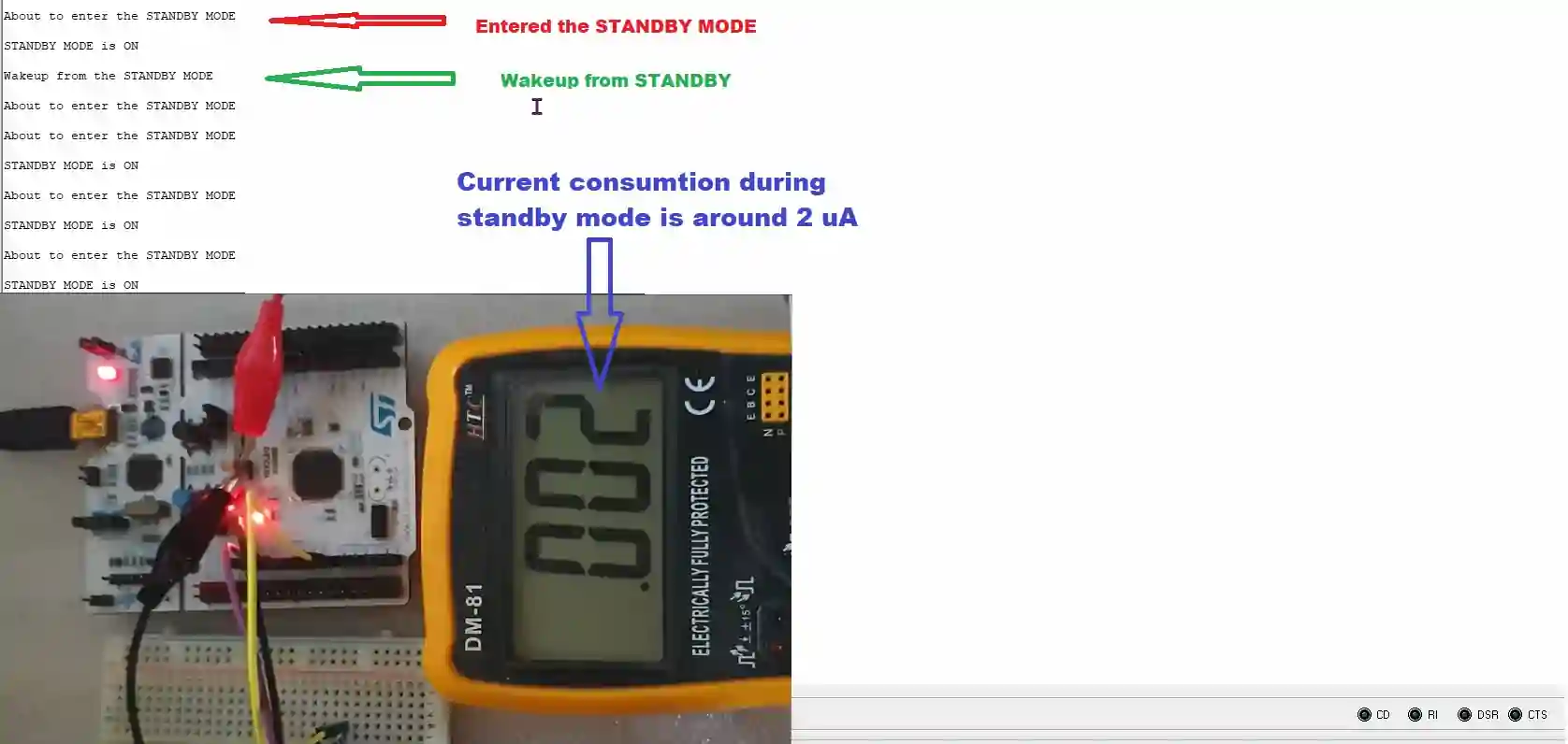
The logs indicate that the MCU successfully enters Standby mode and wakes up whenever an interrupt occurs. In this mode, the power consumption drops to approximately 2 µA.
Key Notes
- Standby mode erases SRAM and peripheral states (unlike Stop mode).
- Always check the SBF flag on reset to know if the MCU woke from Standby.
- Use RTC or backup registers to retain essential information across Standby cycles.
STM32 Standby Mode — Video Tutorial
This video walks through STM32 Standby mode — clearing wake-up flags before entry, configuring the RTC wake-up timer and wake-up pin (PA0), detecting standby wake-up via the SBF flag in main(), and measuring the ~2 µA power consumption on the Blue Pill during standby.
STM32 Low Power Modes — FAQs
Conclusion
STM32 gives you a clean three-tier power saving ladder. Sleep halts the CPU but keeps peripherals and clocks running — fast to enter, fast to exit, but moderate savings. Stop kills all clocks and the main regulator while retaining RAM and registers — much lower power, but requires reconfiguring the system clock on wake-up, or your UART and timers will misbehave. Standby cuts almost everything including the regulator, reaching single-digit microamps, but the price is a full system reset on wake-up — your code starts from main() again and you must check the SBF flag to know why.
The SLEEPONEXIT feature works across both Sleep and Stop modes and is worth using in any interrupt-driven application where the CPU has no background work to do — it eliminates the round-trip to the main loop entirely.
For the lowest system power in practice, remember that the Blue Pill board’s onboard LDO and LEDs add a few milliamps on top of the MCU’s own consumption. For accurate measurements, power the bare MCU directly.
Download STM32 Low Power Modes Project Files
Complete CubeIDE project with all three examples: SleepMode, StopMode & StandbyMode. Free to download — support the work if it helped you.
Browse More STM32 Tutorials

Interfacing MFRC522 RFID Module with STM32 using SPI
LCD 20X4 using I2C with STM32

STM32 Custom Bootloader (Part 3): CRC Based Application Validation
STM32 Custom Bootloader (Part 4): Implementing OTA FLAG Mechanism

W25Q Flash Series Part 2 – Read Data from Device


Hi, I am using the STM32L073 microcontroller and implementing Standby mode with RTC wake-up, but it is exiting the mode immediately. how to solve this?
Make sure to clear all flags before entering standby
__HAL_PWR_CLEAR_FLAG(PWR_FLAG_SB);
__HAL_PWR_CLEAR_FLAG(PWR_FLAG_WU);
__HAL_RTC_WAKEUPTIMER_CLEAR_FLAG(&hrtc, RTC_FLAG_WUTF);
Also confirm if RTC is configured properly. You can try waking up with only the wakeup pin first, not relying on RTC at all.
In stm32f103c8t6 how can we exit from stand by mode using Auto wake up. can u please make a video on that?
using the RTC Alarm. It is already explained in the tutorial.
Hello , isue a dual-core st ( stm32h7) i need put all system in standby mode , but i only use m4core. My m7 core don´t have app yet.
I use the hal function ( HAL_PWR_EnterStandbyMode), my consumption does not go down, which means that the system does not go to full standby..
how can i do?
For sleep mode, you use an arbitrary GPIO pin to wake up MCU. Can I use any pin to wake it up from standby mode?
Hi! Using this example is possible to standby minutes or hours?? Because I tried to change the time of the standby and it only works from 1-30 seconds
The definition of HAL_RTCEx_SetWakeUpTimer_IT function is as follows:
HAL_RTCEx_SetWakeUpTimer_IT (RTC_HandleTypeDef * hrtc, uint32_t WakeUpCounter, uint32_t WakeUpClock)
The “WakeUpCounter” is 32 bit variable, so you can’t input higher value than that.
You can adjust the clock and other things as mentioned in the comment section (where I have used this function) to set the time as per your need.
Thanks!
==> WakeUpCounter = ~5s/0.0005s = 20000 = 0x2710
????
==> WakeUpCounter = ~5s/0.0005s = 10000 = 0x2710
Hi. I boot with stm32L010C6Tx. I am in standby mode. While waiting in standby mode, it shows between 3.1 micro amps and 50 micro amps 50 microamps is too high, I can’t use it like this. . I turned off all peripherals. What else should I turn off? Why coul
void SystemClock_Config(void);
static void MX_GPIO_Init(void);
static void MX_LPUART1_UART_Init(void);
static void MX_I2C1_Init(void);
static void MX_ADC_Init(void);
static void MX_RTC_Init(void);
if (__HAL_PWR_GET_FLAG(PWR_FLAG_SB) != RESET) {
__HAL_PWR_CLEAR_FLAG(PWR_FLAG_SB);
printf(“Wakeup from the STANDBY MODE\n\n”);
for (int i = 0; i < 20; i++) {
HAL_GPIO_TogglePin(GPIOC, GPIO_PIN_13);
HAL_Delay(200);
}
HAL_PWR_DisableWakeUpPin(PWR_WAKEUP_PIN1);
HAL_RTCEx_DeactivateWakeUpTimer(&hrtc);
}
__HAL_PWR_CLEAR_FLAG(PWR_FLAG_WU);
__HAL_RTC_WAKEUPTIMER_CLEAR_FLAG(&hrtc, RTC_FLAG_WUTF);
printf(“About to enter the STANDBY MODE\n\n”);
for (int i = 0; i < 5; i++) {
HAL_GPIO_TogglePin(GPIOC, GPIO_PIN_13);
HAL_Delay(750);
}
HAL_PWR_EnableWakeUpPin(PWR_WAKEUP_PIN1);
if (HAL_RTCEx_SetWakeUpTimer_IT(&hrtc, 0x5A55, RTC_WAKEUPCLOCK_RTCCLK_DIV16)
!= HAL_OK) {
Error_Handler();
}
printf(“STANDBY MODE is ON\n\n”);
HAL_GPIO_DeInit(GPIOC, GPIO_PIN_13);
HAL_GPIO_DeInit(GPIOA, SDIO_Pin);
HAL_GPIO_DeInit(GPIOA,GPO3_Pin);
HAL_GPIO_DeInit(GPIOA,BUZZER_Pin);
HAL_GPIO_DeInit(GPIOA, GPIO_PIN_0);
HAL_GPIO_DeInit(GPIOA, CSB_Pin);
HAL_GPIO_DeInit(GPIOA,FCSB_Pin);
HAL_GPIO_DeInit(GPIOA,SCLK_Pin);
HAL_UART_DeInit(&hlpuart1);
HAL_I2C_DeInit(&hi2c1);
HAL_ADC_DeInit(&hadc);
HAL_PWR_EnterSTANDBYMode();
Awesome explanation!
Thanks
I tried pay pal for donation but it failed. will try something else
Many thanks!
But, I tried to wakeup stm32L053 (nucleo stm32l053) from ALARM A and… nothing! Of course, I used the directives:
__HAL_RTC_ALARM_CLEAR_FLAG(&hrtc, RTC_FLAG_ALRAF);
__HAL_RTC_ALARMA_ENABLE(&hrtc)
before HAL_PWR_EnterSTANDBYMode().
(The line “if (HAL_RTCEx_SetWakeUpTimer_IT(&hrtc, 0x2710, … ” was commented to eleminate effects of WakeUpTimer).
Why this problem appeared?
Thanks your time for your excellent explanation. I found some problem for the standby. Each time when turn on the MCU, it will print “wakeup from standby”, Actually it should not happen until enter standby then exit from standby mode. Also each time when wake up by Wakeup pin (rising PA0 ) it prints “wakeup from standby” twice. So far I haven’t found how to fix that.
that’s an unusual behavior. I would recommend that you debug your code. reset the mcu and step over each function. while doing so, check the contents of PWR_CSR register. The SBF bit is set when the mcu wakes up from standby. SO in case of reset, this shouldn’t be set.
stand_by modda 2mA e kadar düşüyor. vidyoda uA seviyelerinde görünüyor. kod aynı olduğu halde 2mA görüyorum. yardım edermisiniz
maybe urs is not entering the standby.. blink some LED before entering the sleep mode so that you can confirm this
Really nice work. You deserve for much more viewers :O