ATtiny817 Xplained mini || Clock setup || LED Blink
In this series of tutorials we will cover the ATtiny817 AVR controller. I have the ATtiny817 xplained mini evaluation board from the microchip, and I will cover all the tutorials of the AVR series on this board.
The reason for choosing this board is that it has the onboard programming and debugging support. Also it is an official board from the microchip itself.
This is the first tutorial of this series. So today we will see how to create our first project in the microchip studio, how to configure the clock, and how to blink the LED on board.
Below are some features of the ATtiny817 xplained mini evaluation kit.
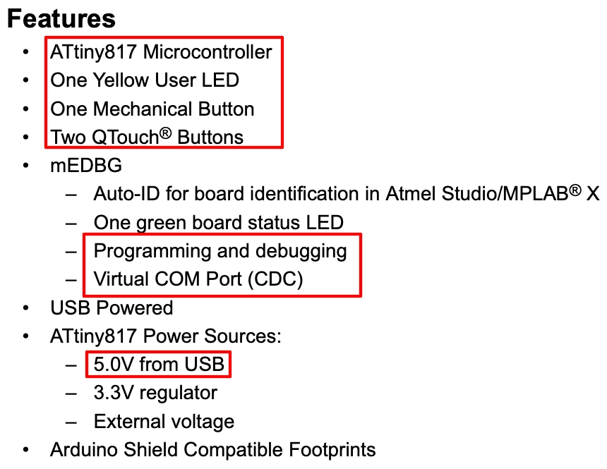
The board can be powered directly from the USB and it has the support for programming and debugging. So we don’t need to connect any additional hardware to power or program it.
VIDEO TUTORIAL
You can check the video to see the complete explanation and working of this project.
Create project in microchip studio
We will start by first creating a new project in the microchip studio. We will use the microchip studio available at https://www.microchip.com/en-us/tools-resources/develop/microchip-studio#
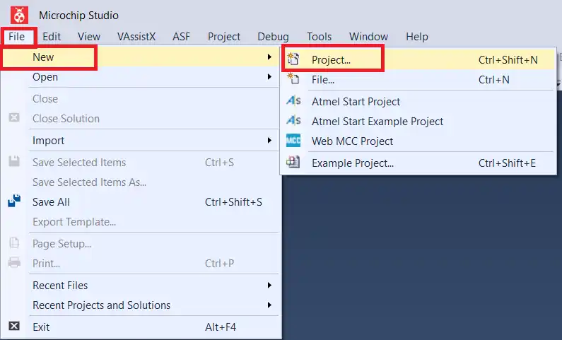
After installing the IDE, click File -> New -> Project
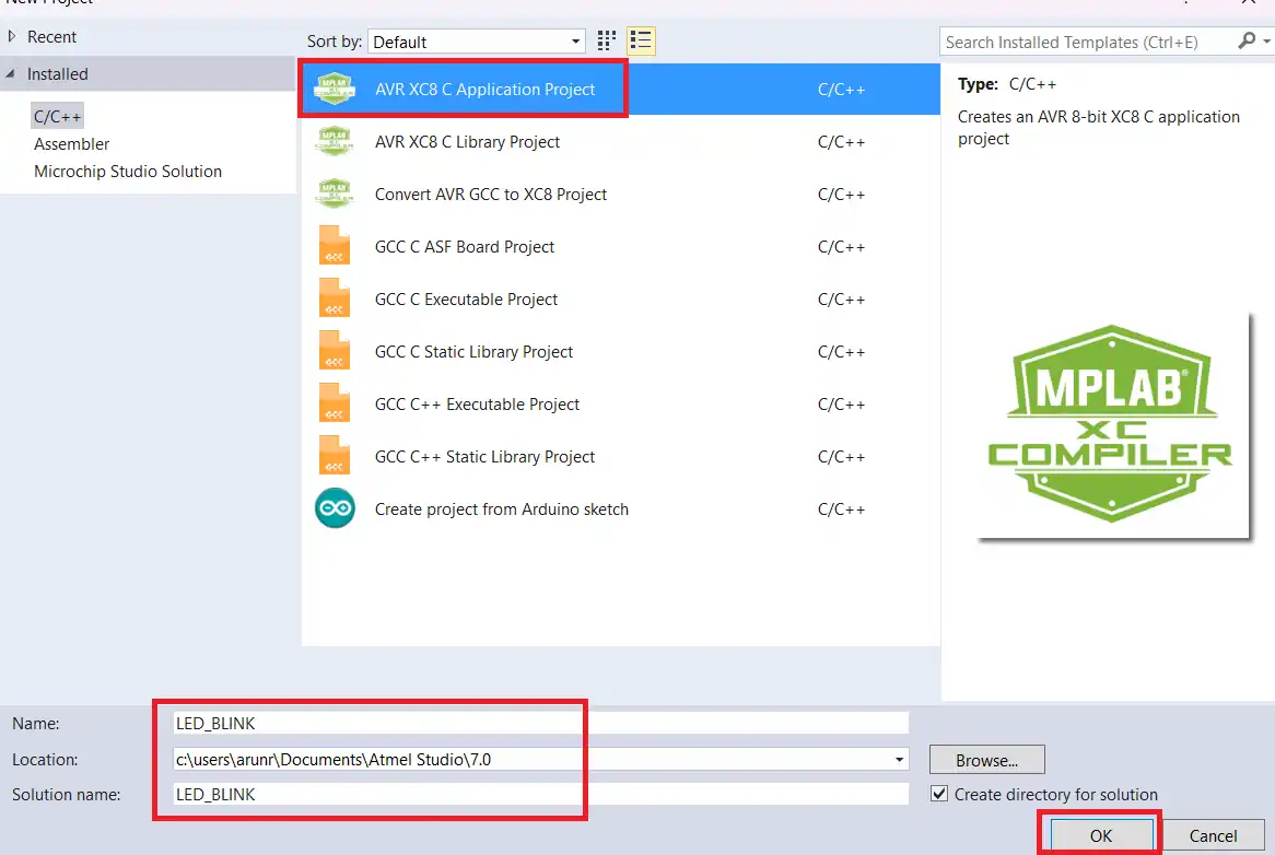
Then click on XC8 C Application Project. Give the name to the project, check the project location and click OK.
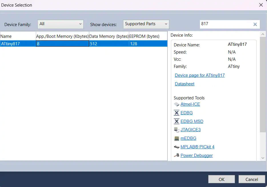
Next in the device selection window, search for the MCU. The select it and click OK.
Below is the final project with regenerated main file.
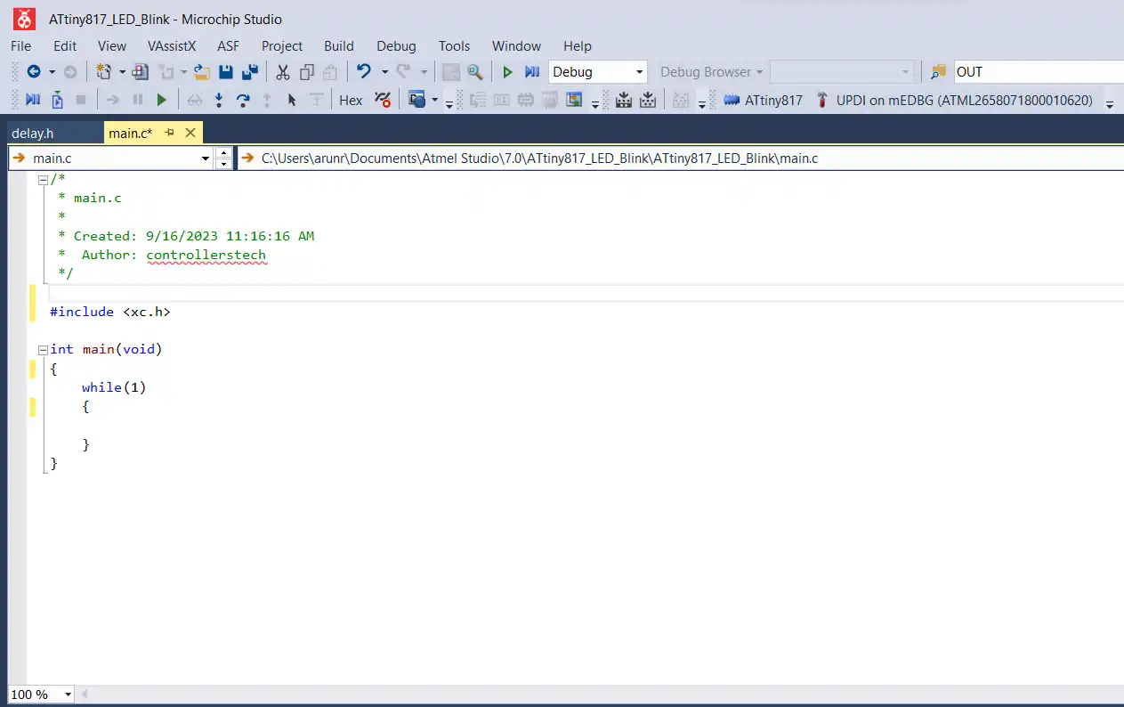
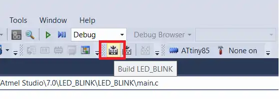
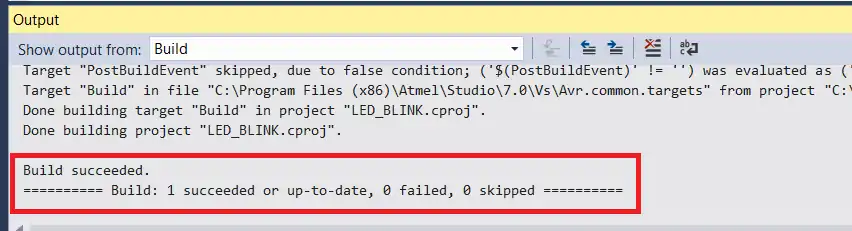
If you build the pre generated code, the output window should show 0 errors.
The Clock configuration
The Clock controller in the ATtiny817 is responsible for handling all the clock related operations. Below are some features of the Clock controller
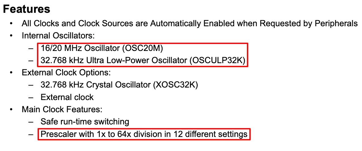
Throughout this series, I will use the internal oscillator of 20MHz and 32.768KHz (If needed for some functions). The Prescaler can be used to divide the clock as per the requirement.
Below is the clock diagram for the MCU.
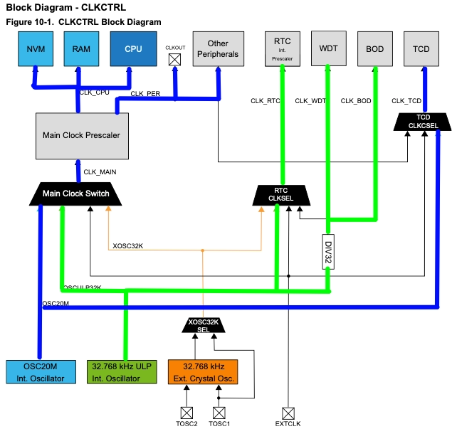
The Blue line is for the internal 20MHz Clock source, and the Green line is for the internal 32.768KHz CLK source. We can clock everything using these 2 oscillators.
In today’s tutorial, we are going to blink the LED, so I am going to work with the internal 20MHz oscillator.
The first Register in the Clock control section is Main Clock Control A (MCLKCTRLA)
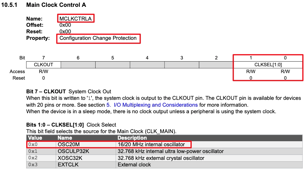
To set the internal 20MHz oscillator, we need to write 0 to the CLKSL (1:0) bits of the MCLKCTRLA register. Also the 7th bit of the register configures if you want the clock output on the CLKOUT pin. I am keeping it 0, as I don’t need the clock output.
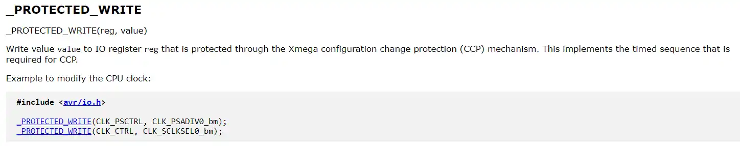
This Register has the Configuration Change Protection (CCP). This means we can not write the data directly to the register. We need to write using the _PROTECTED_WRITE function as shown in the image below.
void clkInit(void)
{
_PROTECTED_WRITE(CLKCTRL.MCLKCTRLA, 0); // Internal 20MHz OSC, CLKOUT=0I have created a new function, clkInit, for the clock configuration. Also, I am configuring the MCLKCTRLA register with the value 0.
The next register is the Main Clock Control B (MCLKCTRLB). This register can be used to control the prescaler for the main clock. The prescaler further divides the clock from the oscillator and sets it as per the user’s requirement.
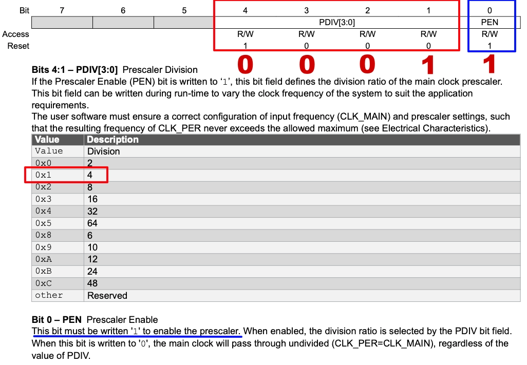
The 0th bit of this register (PEN) enables/disables the prescaler. I am enabling the prescaler by setting the bit to 1.
The PDIV bits (4:1) are used to set the prescaler value. Our main clock from the internal oscillator is of 20MHz. I am using the prescaler of 4 to reduce the main clock to 20/4=5MHz.
To set the prescaler of 4, we need to write 0x1 to the PDIV bits, and to enable the prescaler, we need to write a 1 to the PEN bit. Our final data for this register is 0 0 0 1 1(0x03).
_PROTECTED_WRITE(CLKCTRL.MCLKCTRLB, 0x03); // PEN=1, DIV=4Next we are interested in the Main Clock Status Register (MCLKSTATUS). This register can be used to check the status of the various oscillators.
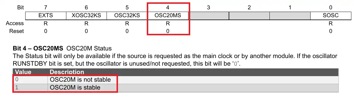
For the internal Oscillator of 20MHz, the bit OSC20MS (bit 4) indicates if the oscillator is stable or not.
We will wait for this bit to set to 1, so to make sure that the oscillator is stable.
	while ((CLKCTRL.MCLKSTATUS & (1<<4)) == 0);  // wait for the osc to stabilize.
}This is the end of the clock configuration. We have used the internal oscillator of 20MHz along with the prescaler of 4, so our main clock is 5MHz. Now we need to define it in the main file so that the delay functions can work accordingly.
#define F_CPU 5000000
#include <xc.h>
#include <util/delay.h>Here I have defined the CPU clock to be 5 MHz. Also I have included the delay library for the delay functions to work.
Controlling the output pin
Now that our clock is configured, we will configure the pin as output and control its state. Let’s start with setting the direction of the pin first.
The ATtiny817 have different registers to control the direction of the pin. First we have the DIR register as shown below.
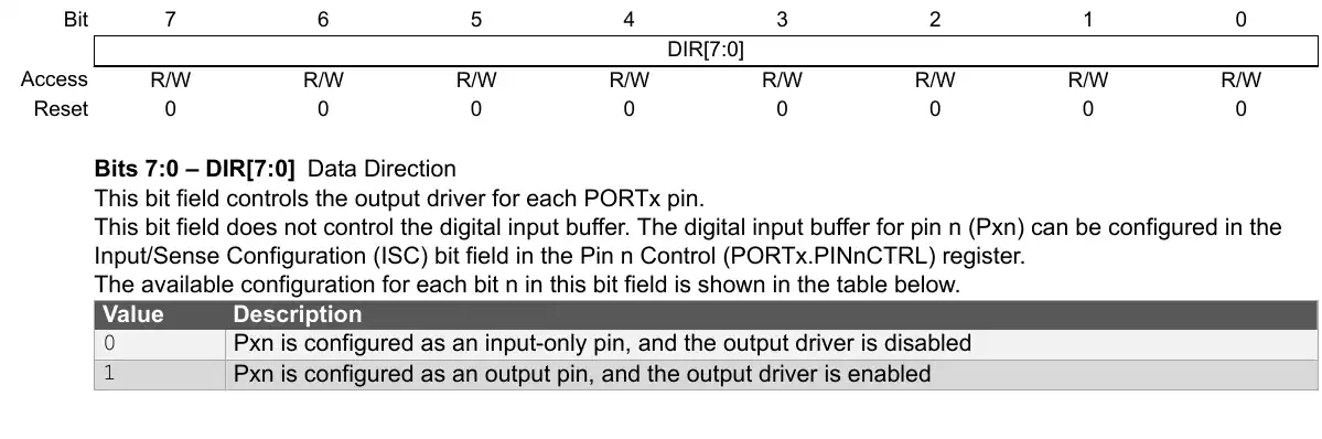
To set the pin output or input, we can write a 1 or 0 respectively to the particular bit of the register. For example, to set the pin PC0 as output we can write PORTC.DIR = 1<<0. This statement will set the pin PC0 as output, but it will also set other pins as input.
To shield the other pins, we can first read the register, then modify the 0th bit, and then write the data back to the register. This can be done as follows PORTC.DIR |= 1<<0
Alternatively, to set a particular pin as output or input, we can also use the DIRSET and DIRCLR Registers.
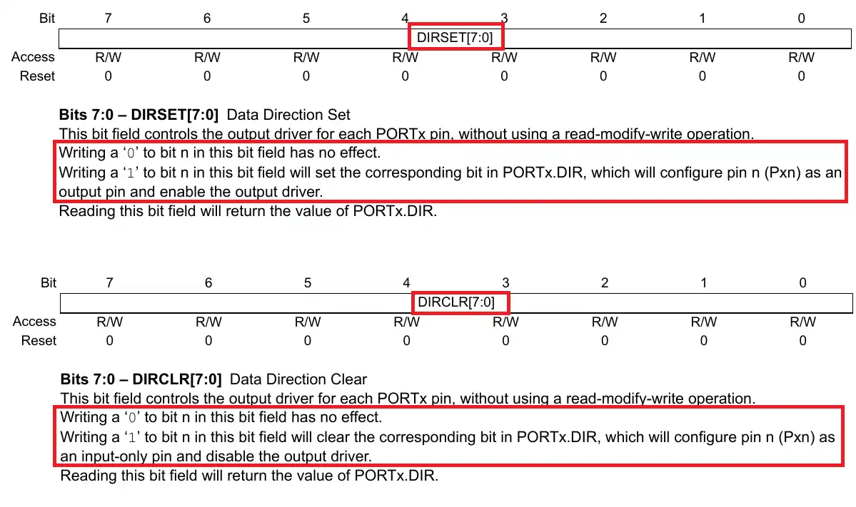
To set the pin PC0 as output, we can use the DIRSET Register, PORTC.DIRSET = 1<<0. And to set the pin PC0 as input, we can use the DIRCLR Register, PORTC.DIRCLR = 1<<0.
We can use either of the above mentioned methods to set the pin as output. The LED is connected to the PC0, so we will set it as output.
int main(void)
{
	clkInit();
PORTC.DIR |= (1<<0); //Set PC0 as Output, <span style="background-color: initial; font-family: inherit; font-size: inherit; font-weight: 600;">PORTC.DIRSET = 1<<0 can also be used</span>In the main function, we will first initialize the clock, and then set the pin PC0 as output.
Now we will blink the LED in the while loop. To blink the LED, we need to set the pin PC0 as HIGH and LOW after some interval of time. The MCU again has different registers to set and reset the state of the pin.
First we have the OUT Regiser.
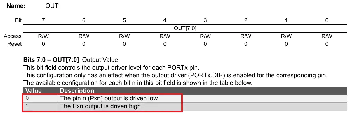
Writing a 1 to the particular bit sets the pin as HIGH, and writing a 0 resets the pin to LOW. But just like the DIRection register, this register also affects the states of the other pins. So we can set and reset one particular pin by first reading the register, then modifying one bit, and writing the data back to the register.
PORTC.OUT |= 1<<0;
_delay_ms(1000);
PORTC.OUT &= ~(1<<0);
_delay_ms(1000);The above code shows how we can blink the LED by modifying the bit 0 of the OUTput Register. I have provided 1 second delay, so the LED will remain On for 1 second, and then OFF for another second.
Alternatively, we have the OUTSET and OUTCLR Registers to control the state of only 1 pin.
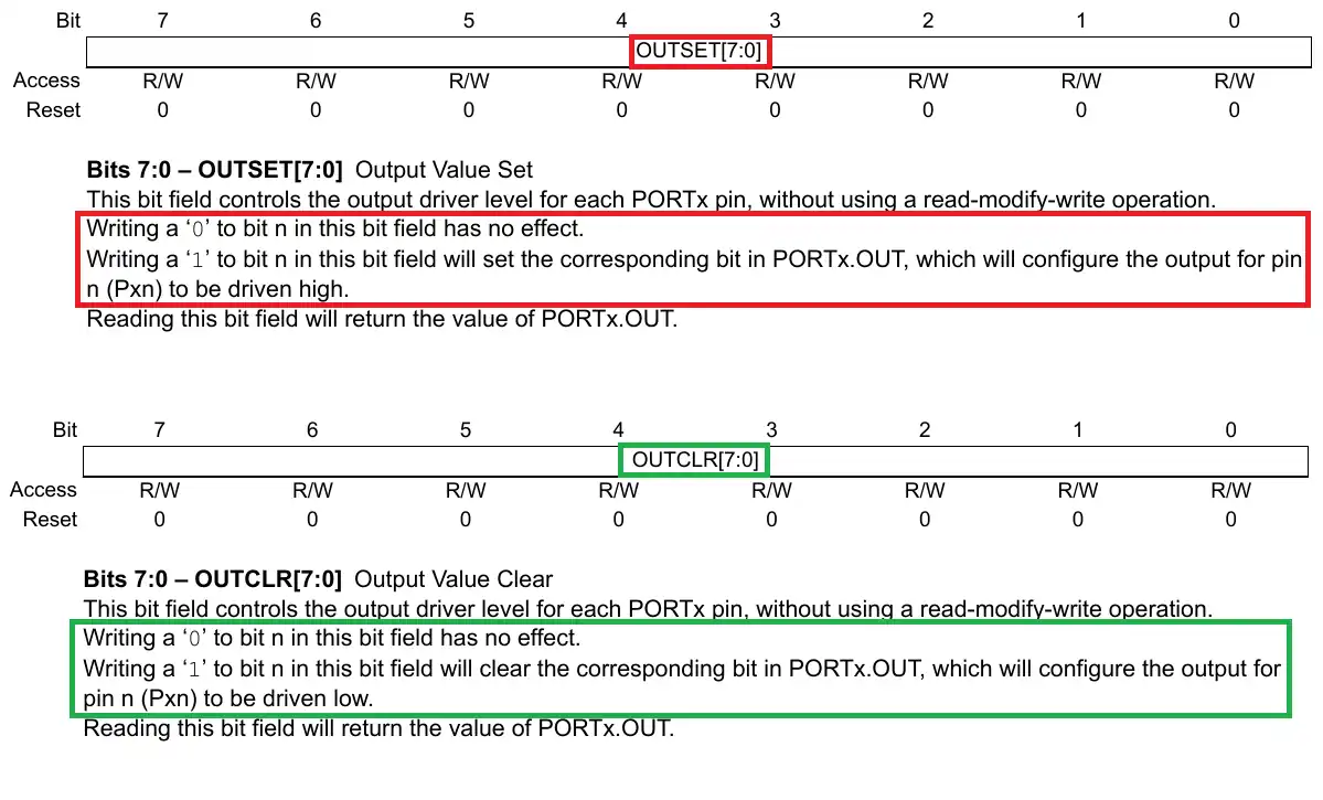
Writing a 1 to the particular bit of OUTSET Register will set the pin as HIGH without affecting other pins of this port. While writing a 0 does not have any affect on the state of the pin.
Similarly, Writing a 1 to the particular bit of OUTCLR Register will Reset the pin to LOW without affecting other pins of this port. While writing a 0 does not have any affect on the state of the pin.
PORTC.OUTSET = 1<<0;
_delay_ms(1000);
PORTC.OUTCLR = 1<<0;
_delay_ms(1000);The above code shows how we can blink the LED by modifying the bit 0 of the OUTSET and OUTCLR Registers. I have provided 1 second delay, so the LED will remain On for 1 second, and then OFF for another second.
We have another alternative to blink the LED. The OUTTGL Register can be used to toggle the state of a particular output pin.
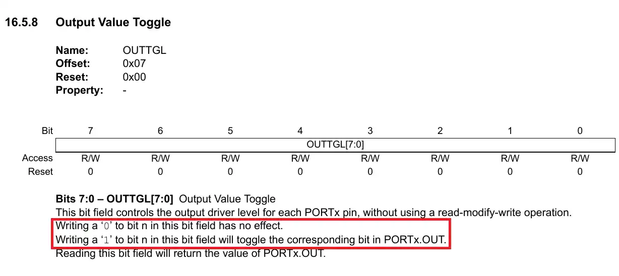
Writing a 1 to the particular bit of OUTTGL Register will toggle the state of a particular pin without affecting other pins of this port. While writing a 0 does not have any affect on the state of the pin.
PORTC.OUTTGL = 1<<0;
_delay_ms(1000);he above code shows how we can blink the LED by modifying the bit 0 of the OUTTGL Register. I have provided 1 second delay, so the LED will remain On for 1 second, and then OFF for another second.
We can use either of the above mentioned methods to blink the LED. The result is shown below.

As you can see in the gif above, the LED is blinking every 1 second. You can check out the video for more detailed working and debugger usage.

