Updated On: February 9, 2026
How to Implement LIN Protocol on STM32 Using UART
In this tutorial, we will learn how to implement the LIN (Local Interconnect Network) protocol using the STM32 UART peripheral. LIN is widely used in automotive applications for low-cost, reliable communication between electronic control units. Unlike standard UART communication, LIN follows a defined frame structure that includes a break field, sync byte, protected identifier, data bytes, and checksum.
In this first part, we will configure the STM32 as a LIN master and generate a complete LIN frame. We will calculate the protected ID and enhanced checksum in software, transmit the frame using UART in LIN mode, and verify the output using a logic analyzer. This will help you understand how LIN communication works at the frame level before moving on to slave implementation in the next part.
Basically we will see if the data transmitted is recognized as a valid LIN frame by the analyzer. later in the upcoming tutorials we will connect an actual slave device and try to communicate with it.
What is LIN Protocol?
LIN stands for Local Interconnect Network. It is a low-cost serial communication protocol mainly used in automotive applications. LIN was developed to provide a simple and economical alternative to more complex communication systems like CAN, especially for devices that do not require high bandwidth or real-time performance.
LIN is based on standard UART communication but adds a defined frame structure, synchronization mechanism, and error detection to ensure reliable data exchange between nodes.
Why LIN Was Developed
Modern vehicles contain dozens of small electronic control units (ECUs) responsible for tasks such as window control, seat adjustment, mirror positioning, lighting, and climate control. Using CAN for all these nodes would increase system cost and complexity.
LIN was introduced to reduce wiring complexity and hardware cost by using a single-wire communication bus with a master–slave architecture. In a LIN network:
- One node acts as the master
- Multiple nodes act as slaves
- The master controls all communication on the bus
This makes LIN ideal for simple, low-speed control applications.
Where LIN Is Used
LIN is widely used in automotive body electronics, including:
- Power windows
- Door locks
- Seat controllers
- Rain and light sensors
- Climate control systems
- Steering wheel switches
Because of its simplicity and cost-effectiveness, LIN is commonly used alongside CAN in modern vehicles, where CAN handles high-speed communication and LIN manages low-speed peripheral devices.
LIN 2.1 Frame Structure: Header, Response, and Field Explanation
I will be covering the LIN version 2.1 in this series. As the the specification manual, a typical L:IN frame is shown in the picture below.
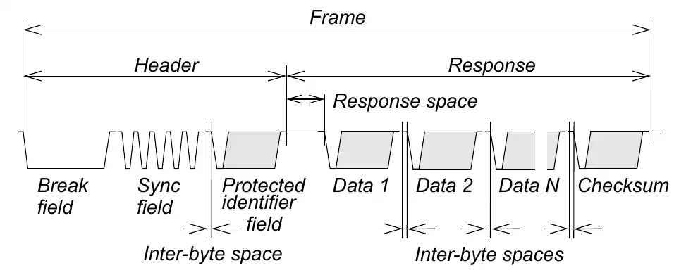
The lin frame consists of the Header and the Response. The Header further contains the Break Field, the Sync Field and the Protected ID. The Response contains the Data bytes and the checksum byte.
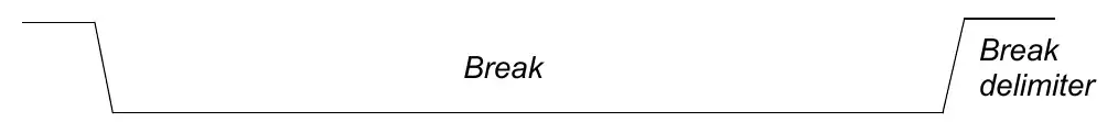
Break
The break field is used to signal the beginning of a new frame. A break field is always generated by the master task (in the master node) and it shall be at least 13 nominal bit times of dominant value, followed by a break delimiter, as below.
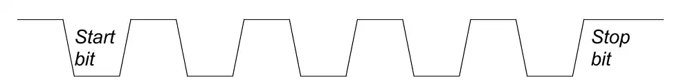
Sync
Sync is a byte field with the data value 0x55 as shown in the image below.
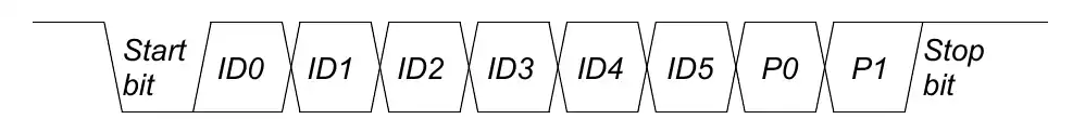
Protected ID
A protected identifier field consists of two sub-fields: the frame identifier and the parity. Bits 0 to 5 are the frame identifier and bits 6 and 7 are the parity.
Six bits are reserved for the frame identifier, values in the range 0 to 63 can be used. The frame identifiers are split in three categories:
- Values 0 to 59 (0x3B) are used for signal carrying frames
- 60 (0x3C) and 61 (0x3D) are used to carry diagnostic and configuration data
- 62 (0x3E) and 63 (0x3F) are reserved for future protocol enhancements
The parity is calculated on the frame identifier bits as shown below:
- P0 = ID0 ⊕ ID1 ⊕ ID2 ⊕ ID4
- P1 = ¬(ID1 ⊕ ID3 ⊕ ID4 ⊕ ID5)
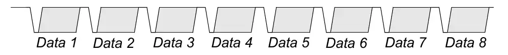
Data
A frame carries between one and eight bytes of data. A data byte is transmitted as part of a byte field. For data entities longer than one byte, the entity LSB is contained in the byte sent first and the entity MSB in the byte sent last (little-endian).
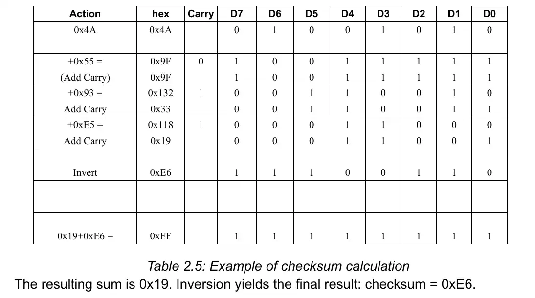
Checksum
The last field of a frame is the checksum. The checksum contains the inverted eight bit sum with carry over all data bytes or all data bytes and the protected identifier. Checksum calculation over the data bytes and the protected identifier byte is called enhanced checksum and it is used for communication with LIN 2.x slaves. Use of classic or enhanced checksum is managed by the master node and it is determined per frame identifier; classic in communication with LIN 1.x slave nodes and enhanced in communication with LIN 2.x slave nodes.
A typical example of checksum calculation is shown below.
STM32 CubeMX Configuration
Below is the image showing the configuration of the UART in the Lin mode.
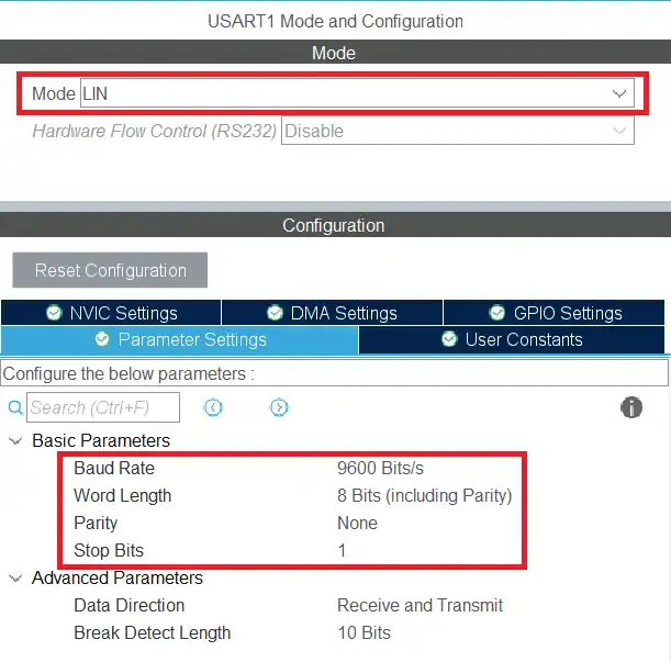
The USART1 is configured in the Lin Mode. The Lin protocol supports the transfer up to the baud rate of 200 Kbps, but here I am using 9600 bps. The data size is set to 8 bits with no parity and 1 stop bit.
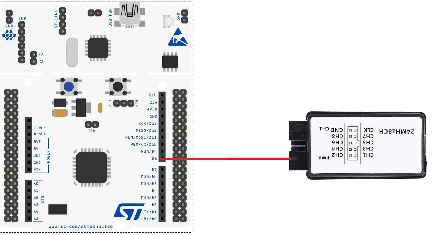
Below the image shows the Logic Analyzer is connected to the USART1 TX pin (PA9).
STM32 HAL code for LIN protocol
Below is the LIN frame. We will send the data according to it.
The Break field will be sent by using the HAL function and the Sync field has the fixed value 0x55. We will prepare the Protected ID first and then the checksum.
Protected ID
I have already mentioned that the PID consists of two sub-fields: the frame identifier and the parity. Bits 0 to 5 are the frame identifier and bits 6 and 7 are the parity. The parity is calculated on the frame identifier bits as shown below:
- P0 = ID0 ⊕ ID1 ⊕ ID2 ⊕ ID4
- P1 = ¬(ID1 ⊕ ID3 ⊕ ID4 ⊕ ID5)
uint8_t pid_Calc (uint8_t ID)
{
	if (ID > 0x3F) Error_Handler();
	uint8_t IDBuf[6];
	for (int i=0; i<6; i++)
	{
		IDBuf[i] = (ID>>i)&0x01;
	}
	uint8_t P0 = (IDBuf[0]^IDBuf[1]^IDBuf[2]^IDBuf[4])&0x01;
	uint8_t P1 = ~((IDBuf[1]^IDBuf[3]^IDBuf[4]^IDBuf[5])&0x01);
	ID = ID | (P0<<6) | (P1<<7);
	return ID;
}The function pid_Calc takes the actual ID as the parameter. We have only 6 bits for the ID, so if the ID is greater than 0x3F (63), we will call the error handler.
- Here we will first extract each bit from the 6 bit ID and store them in the IDBuf.
- The parity bit P0 will be calculated by performing the XOR operation between the ID 0 1 2 and 4.
- Similarly, to calculate the parity bit P1, we will first perform the XOR operation between the ID 1 3 4 and 5, and then negate the value obtained.
- Now we will add the parity bits with the actual ID and store the final value in the ID variable itself.
- The value will then be returned.
Checksum
The checksum contains the inverted eight bit sum with carry over all data bytes or all data bytes and the protected identifier. Below is the method to calculate the Enhanced checksum.
uint8_t checksum_Calc (uint8_t PID, uint8_t *data, int size)
{
	uint8_t buffer[size+2];
	uint16_t sum = 0;
	buffer[0] = PID;
	for (int i=0; i<size; i++)
	{
		buffer[i+1] = data[i];
	}

	for (int i=0; i<size+1; i++)
	{
		sum += buffer[i];
		if (sum>0xff) sum = sum-0xFF;
	}

	sum = 0xFF-sum;
	return sum;
}The function checksum_Calc takes the following parameters:
- @PID the protected ID
- @*data the pointer to the actual data bytes
- @size the size of the actual data
Since we need to add all the data bytes and the PID, we need to first store them in a single buffer. The buffer array is defined to do the same. The first element of the buffer array holds the PID value and the rest of them will store the data bytes.
Once we have all the data at once place, we will start adding it. The variable sum is 16 bit in size and it stores the result of the addition. Whenever the value of the sum is higher than 0xFF (255), we will subtract 0xFF from it.
After all the calculation is over, the sum variable will have a 8 bit result value in it. Finally we need to invert the result, so subtract the sum from 0xFF (255). This value will be returned in the end.
The main Function
Below is the code in the main function.
int main ()
{
  ...
  ...
  while (1)
  {

	  TxData[0] = 0x55;  // sync field
	  TxData[1] = pid_Calc(0x34);
	  for (int i=0; i<8; i++)
	  {
		  TxData[i+2] = i;
	  }
	  TxData[10] = checksum_Calc(TxData[1], TxData+2, 8);   //lin 2.1 includes PID, for line v1 use PID =0

	  HAL_LIN_SendBreak(&huart1);
	  HAL_UART_Transmit(&huart1, TxData, 11, 1000);
	  HAL_Delay(1000);
  }
}We will send the TxData buffer via the UART, so we need to prepare it first.
- First store the sync bytes (0x55) to the buffer.
- The next element will contain the PID. Here I am using the ID 0x34, which will be then converted to the PID.
- Then copy the data bytes to the buffer. I am storing 8 data bytes with the values starting from 0 to 7.
- The last element of the buffer will contain the checksum.
- I am using the Lin version 2.1, so the PID must be included in the checksum.
- For the lin version 1.x, the PID is not needed and hence you can just pass the value 0 for the PID.
After preparing the TxData buffer, we will send it via the UART. The function HAL_LIN_SendBreak is used to send the break field. After sending the break field, we will send the TxData buffer.
STM32 LIN Transmission Result
Below the image shows the frame captured on the logic analyser.
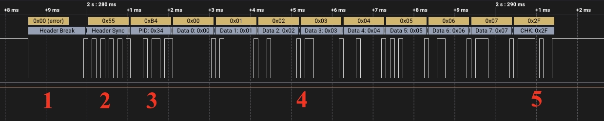
You can see the complete Lin frame in the image above.
- The master sends the break field.
- The sync field is sent next with the byte value of 0x55.
- The third field is the PID. The MCU sends the PID 0xB4, but the ID 0x34 is extracted from it by the Lin analyzer.
- The master then sends the 8 bytes of data. the data ranges from 0x00 to 0x07.
- In the end, the master sends the checksum. This checksum value is correct otherwise the analyzer would have reported it as a wrong value.
So we have received the complete Lin frame at the output. This verifies that our program was correct and we can proceed with it.
Video Tutorial
STM32 LIN Protocol (UART) – Video Tutorial
This video demonstrates how to implement the LIN (Local Interconnect Network) protocol using the STM32 UART peripheral. It covers LIN master configuration, break field generation, sync transmission (0x55), protected ID calculation with parity bits, enhanced checksum calculation for LIN 2.x, and verification of the complete LIN frame using a logic analyzer.
Watch the VideoConclusion
In this tutorial, we explored the fundamentals of the LIN 2.1 protocol and implemented a LIN master using the STM32 UART peripheral. We examined the complete LIN frame structure, including the break field, sync byte, protected identifier with parity bits, data bytes, and the enhanced checksum. By calculating the PID and checksum in software and transmitting the frame using LIN mode, we gained a clear understanding of how LIN communication works at the frame level.
Using a logic analyzer, we verified that the generated frame follows the LIN specification correctly. This confirms that STM32 can reliably operate as a LIN master for low-speed automotive communication. In the next part of this series, we will move forward by connecting a LIN transceiver and establishing communication with a LIN slave node.
Browse More STM32 UART Tutorials
STM32 UART Part 3 – Receive Data in Blocking & Interrupt mode
STM32 UART DMA Receive: Normal & Circular Mode (HAL)
STM32 UART Idle Line: Receive Data via Interrupt & DMA
STM32 UART Part 6 – Half-Duplex Communication (Single-Wire Mode)
STM32 UART Part 7 – How to use one-Wire Protocol
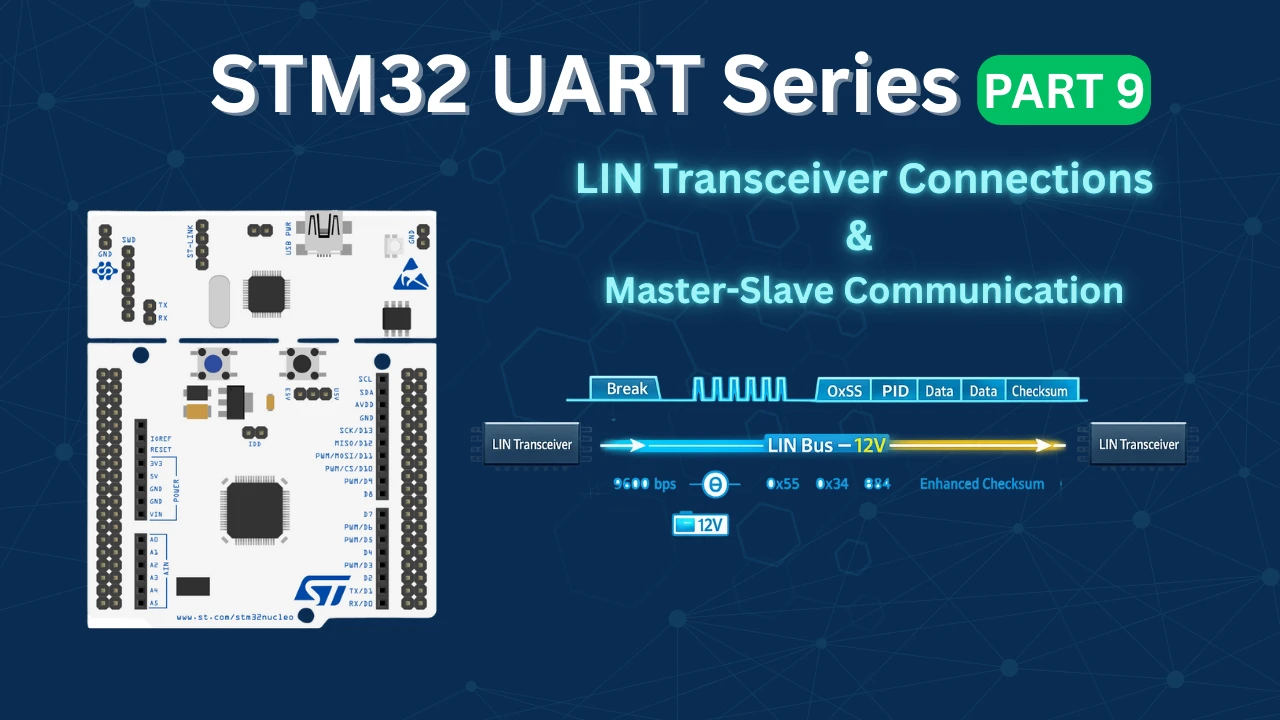
STM32 UART Part 9 – LIN Transceiver Connections & Master-Slave Communication
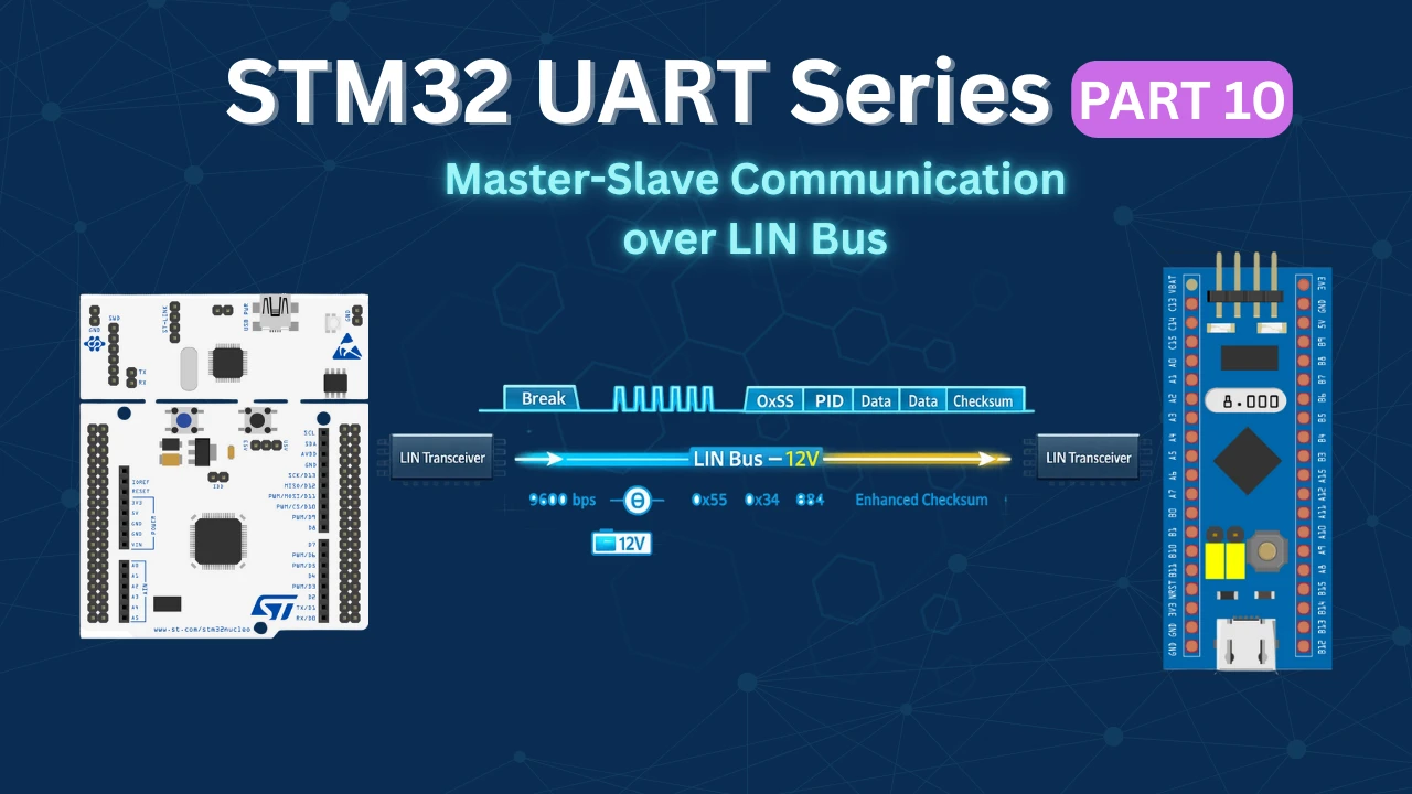
STM32 UART PART 10 – Lin Protocol PART 3
STM32 UART LIN Project Download
STM32 UART LIN FAQs

Subscribe
Login
0 Comments
Newest
