AVR #5. I2C Master PART 1 || Configuration
This is the 5th tutorial in the AVR series using the xplained mini development board, and today we will start with the I2C Master series. In this series, we will develop the code for the I2c master across few tutorials, covering the Write and Read operations to the slave device.
In this particular tutorial we will see the configuration to initialize the I2C bus, and how to write the data to the slave device. To keep the things simple and this tutorial as small as possible, I am not going to connect any slave device to the bus. We will simply check using the oscilloscope, if the master is able to transmit the data. Later in the upcoming tutorials, we will connect an actual slave device and control it using the I2C.
VIDEO TUTORIAL
You can check the video to see the complete explanation and working of this project.
Connection
The I2C required only 2 wires to communicate to another device. The 2 lines are named as SCL (Clock) and SDA (Data). The ATtiny817 has dedicated pins PA1 and PA2 for the I2C communication.
As I mentioned I am not going to connect any slave device and instead connect the oscilloscope to check the data sent by the master. Below is the image showing the connection between the dev board and the logic analyzer.
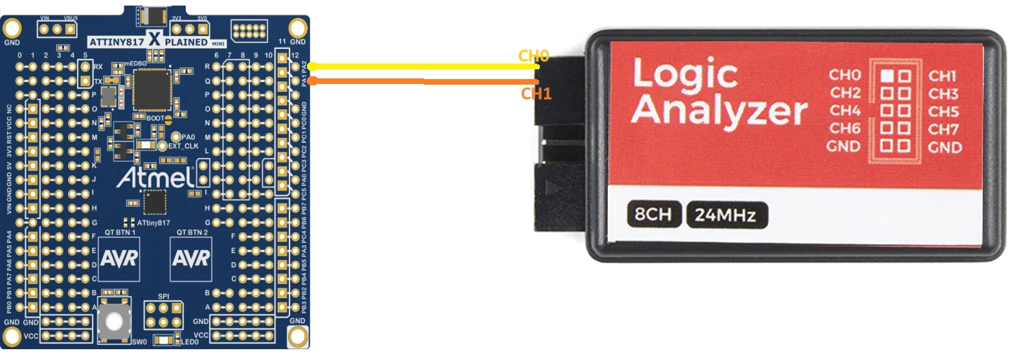
i have connected the SDA (PA1) to the channel 1 and SCL (PA2) to the channel 0 of the analyzer.
Initialize the I2C
We will start with the host Control A Register (MCTRLA). I will only cover the data (bits) that we will modify in these registers. The rest of the bits are kept to their default states.
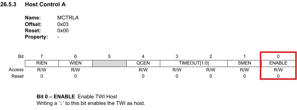
The ENABLE bit is used to enable the TWI, so we will set it to 1.
void I2C_Init (void)
{
TWI0.MCTRLA = TWI_ENABLE_bm; // EN -> 0x01Next is the host control B Register (MCTRLB)
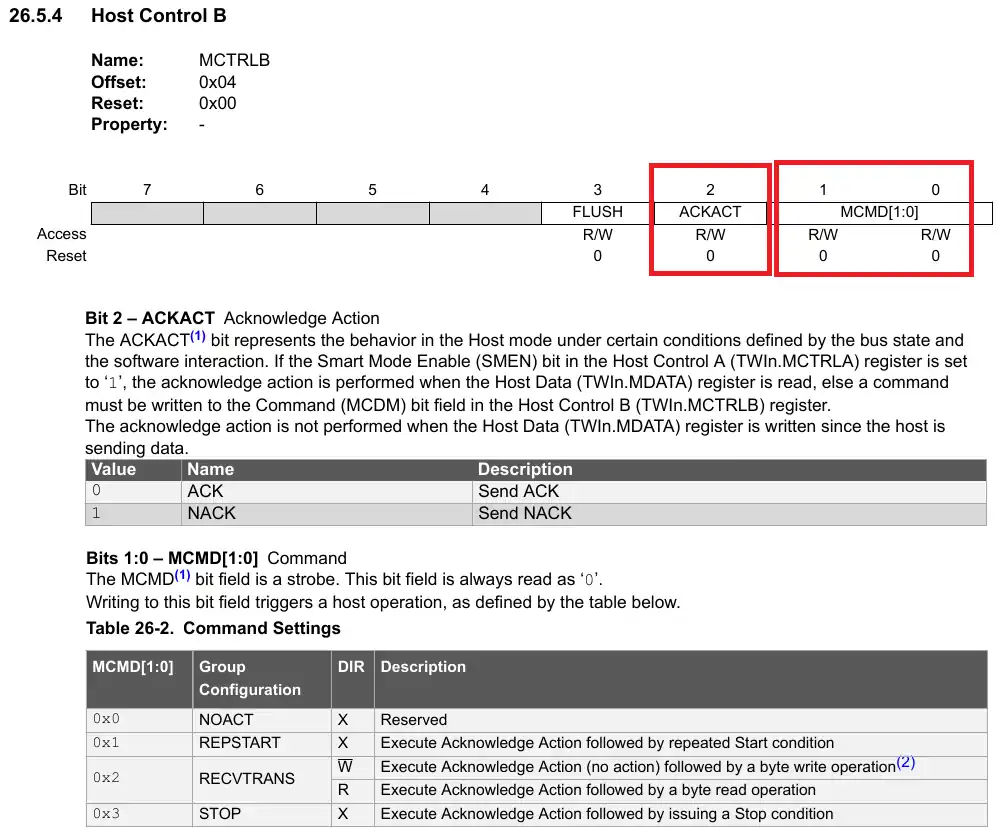
The MCMD (bits 1:0) are the command bits. The host can modify these bits to issue commands like stop, repeated start, ACK or NACK. We will use these command bits later in our code, but we will keep them to 0 during the initialization.
The ACKACT, Acknowledge Action bit is used to store the response (ACK or NACK), the command bits will send to the slave. When we will set the command bits to send the response to th slave, the response will be fetched from this ACKACT bit. During the initialization, we need to set this bit to 1.
TWI0.MCTRLB = TWI_ACKACT_NACK_gc; // NACK enabled -> 0x04Next is the Baud Register (MBAUD). The value in this register determines the frequency of the I2C clock (Fscl).
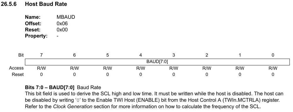
The value for the Baud Register for a particular I2C clock frequency can be calculated using the formula below.
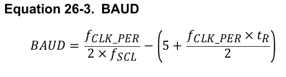
In the above formula, we know the fCLK_PER (Peripheral Clock) = 5MHz. We want the fSCL (I2C Clock) of 100 KHz. The value of tR can be found in the Electrical characteristics of the controller, and for the fSCL <= 100KHz, tR = 1000nS.
Once we put all the values in the formula, the Baud Register value is 17.5 as shown below.
We can’t use the decimal value for a 8 bit Register, so let’s use the value 18.
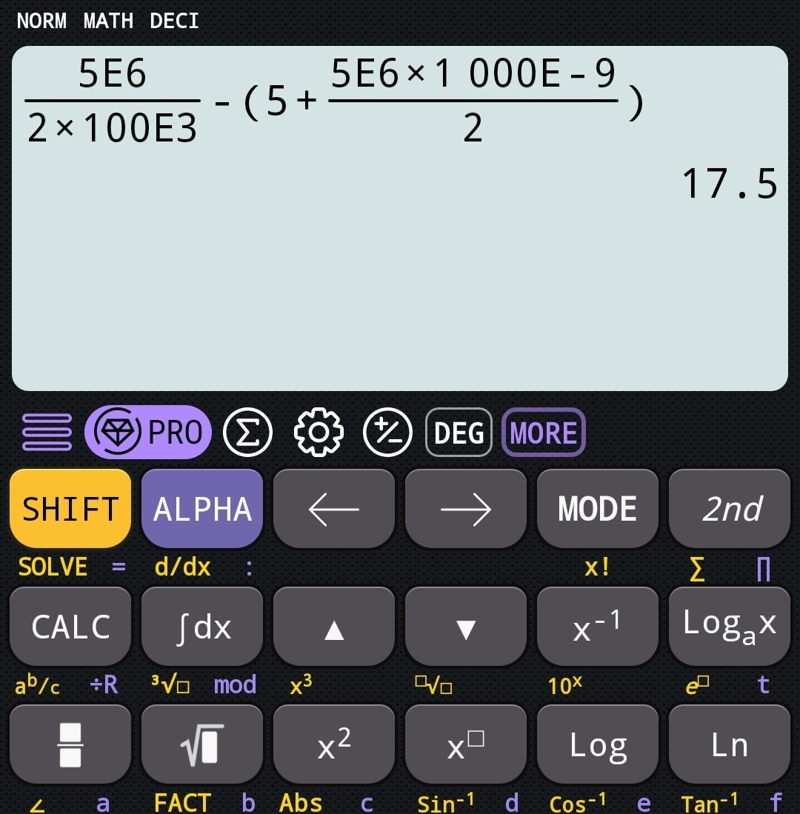
TWI0.MBAUD = 18;Now we need to set the Respective pins for the I2C, and this can be done in the Port Multiplexer (PORTMUX).
The Control B Register (CTRLB)controls the multiplexing for different peripherals. To set the respective pins for the TWI communication, we need to write a 1 to the 4th position in this register.
PORTMUX.CTRLB = 1<<4;  // TWI0 communication
}The final initialization code is shown below.
void I2C_Init (void)
{
TWI0.MCTRLA = TWI_ENABLE_bm; // EN
TWI0.MCTRLB = TWI_ACKACT_NACK_gc; // NACK enabled
TWI0.MSTATUS = 0x00; // clear status register
TWI0.MBAUD = 18;
PORTMUX.CTRLB = 1<<4;  // TWI0 communication
}Master Writes Data
Now that the I2C is initialized, the master will transmit the data to the slave. As I mentioned in the beginning, today’s tutorial does not have any slave connected to the bus, so we will only check if the master is able to send the data. We will monitor the bus with an oscilloscope or logic analyzer.
uint8_t I2C_Write (uint8_t slaveAddr7b, uint8_t *data, uint8_t size)
{The Write functions takes 3 parameters :
- @slaveAddr7b, The 7 bit slave address.
- @*data, The pointer to the data array that need to be transmitted.
- @size, The size of the data.
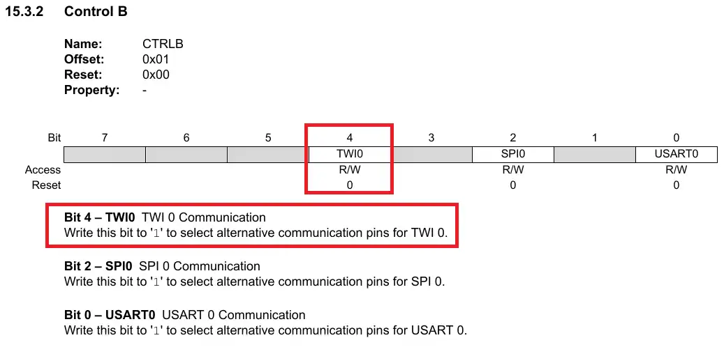
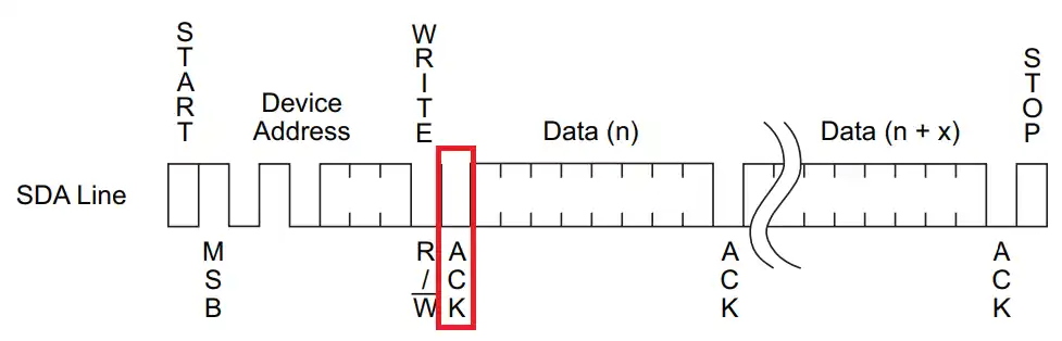
Below the image shows the I2C frame. The master generates the START condition and then send the slave address followed by the Read/Write bit.
The ATtiny817 does not have the means to generate a separate Start condition. Basically when the master writes the address, the start is generated automatically.
		uint8_t write_address = (slaveAddr7 << 1) & 0xFE;
		TWI0.MADDR = write_address;
while (((TWI0.MSTATUS)&TWI_WIF_bm) == 0); // wait for the transmission to completeSince the master is performing the write operation, the R/W bit will be set to 0. So we will shift the 7bit slave address to the left by 1 place and add the 0 to the lsb.
Then write the Address to the Address Register (MADDR), and wait for the write operation to complete.
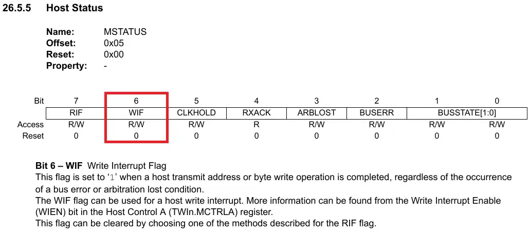
The Write Interrupt Flag bit in the status register is set when the ongoing write (data/address) is complete. We wait for this bit to set after performing any type of write to the slave device.
After the master send the address on the bus, the respective slave (whose address matches with the address sent by the master) sends the ACK response.
This response is received in the 4th bit of the status register (MSTATUS).
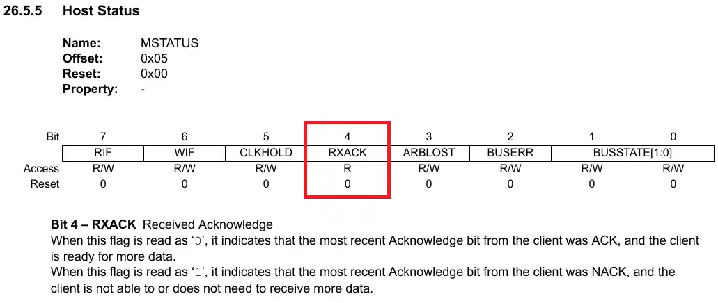
If the address matches with the slave, the slave sends the ACK response and this bit will be reset to 0. So we will check if this bit before writing the data to the slave.
		if (((TWI0.MSTATUS)&(TWI_ACKACT_bm)) == 0)  // if received ACK from slave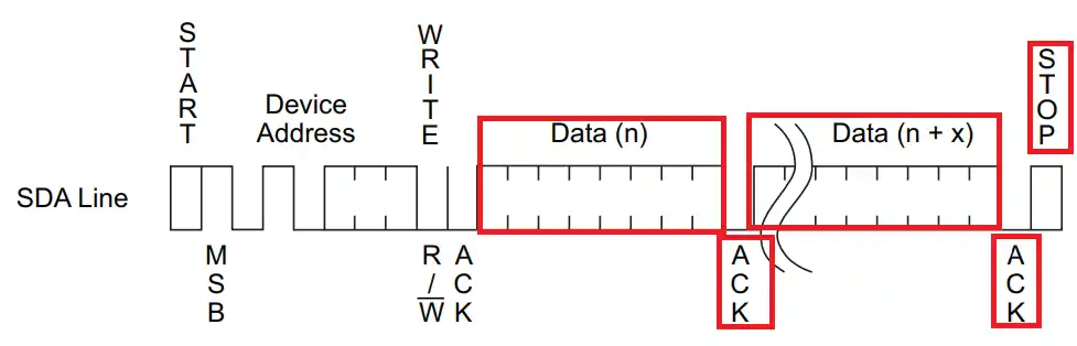
{If the slave ACKnowledged the address, the master will start transmitting data. After each data byte received, the slave will send an ACK response. Once the master has transmitted all the data bytes, it will send the STOP condition.
		if (((TWI0.MSTATUS)&(TWI_ACKACT_bm)) == 0)  // if received ACK from slave
		{
uint8_t indx = 0; // keep track of bytes written
while ((((TWI0.MSTATUS)&(TWI_ACKACT_bm)) == 0) && (indx < size)) // if recvd ACK from slave and we still have the data to write
{
TWI0.MDATA = data[indx++]; // copy data to the data register
while (((TWI0.MSTATUS)&(TWI_WIF_bm)) == 0); // wait for the transmission to complete
if (indx == size) // all the data has been transmitted
{
TWI0.MCTRLB = TWI_MCMD_STOP_gc; // send stop
return 0; // success
}
}
}The indx variable is defined to keep track of number of bytes written to the device. The write is performed in a while loop, which will only run if the master receives the ACK from slave and the indx value is less than the size parameter. This check is performed after writing each byte to the slave device.
To write the data, we copy the data byte into the Data Register (MDATA), then wait for the WIF (Write Interrupt Flag) in the status register to set. This indicates that the data byte has been transmitted successfully.
Once the value of the indx variable is equal to the size parameter, which means all the data bytes has been transmitted, the master will send a STOP condition by modifying the command bits (MCMD) of the Control B Register.
The main code
Below is the code for the main function.
uint8_t datatosend[] = "Hello world";

int main(void)
{
  clkInit();
  I2C_Init();
  _delay_ms(100);

  while(1)
  {
    I2C_Write(0x15, datatosend, 11);
    _delay_ms(1000);
  }
}The dattosend array contains the data we will send to the slave.
In the main function, we will first initialize the clock and then initialize the I2C. I have provided a delay of 100ms for the I2C to initialize properly.
In the while loop we will transmit the data every 1 second. The slave address, 0x15, is just a random address as there is no slave device connected to the bus.
Result
Below the image shows the I2C frame captured by the Logic analyzer.
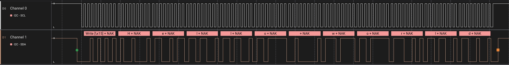
the frame shows the data as follows:
- The START bit is represented by the Green dot.
- The master then send the device address (0x15) with a write request.
- As there is no device on the bus, it receives the NACK response.
- The master continues to send the data (“Hello world”) and receives the NACK response after every byte.
- In the end the master send the STOP condition, which is represented by the orange dot.

