
Home ▸ STM32 Tutorials ▸
Updated On: April 12, 2026
Modbus #4. STM32 as Slave || Read Holding and Input Registers
This is the 4th Tutorial in the Modbus Series, and today we will start the STM32 as a slave Device. This tutorial will cover how the STM32 as a slave device will send a response to the queries regarding reading holding registers and input registers.
We will cover the function codes FC03 and FC04 in this tutorial, but from the slave prospective.
I have already mentioned in the previous modbus tutorials that RS485 is not a requirement by the modbus, rather the mosbus protocol can be used with any communication standard.
Today I am going to use the UART with the modbus protocol. I am using the STM32F446 nucleo board and it’s easier to communicate with the computer using the UART.
VIDEO TUTORIAL
You can check the video to see the complete explanation and working of this project.
CubeMX Setup
Below is the image of the cubeMX setup
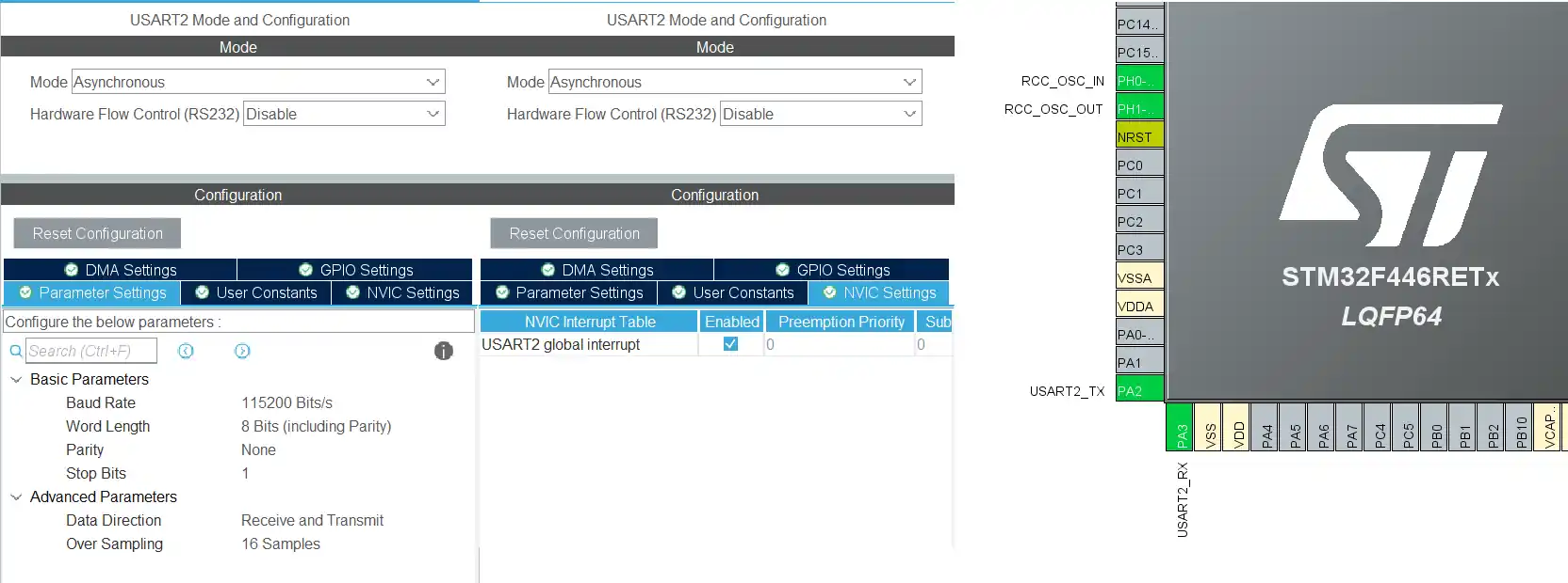
Here I am using the UART2 with the Baudrate of 115200. The configuration is 8-N-1. I have also enabled the interrupt. The pins PA2 and PA3 are configured as the TX and RX pins respectively.
The Master Sotware
I am using the simply modbus master software, which can be downloaded from https://www.simplymodbus.ca/download.htm
The software is shown below

- Here in the RED BOX we have the serial configuration. It is same as what we configured in the cubeMX.
- The 115200-8-N-1 configuration
- The GREEN BOX contains the slave ID, The start Register, the number of Registers master wants to Read, the function code and the Register size.
- The BLACK BOX contains the query to be sent by the master. It is based on the setup we did in the Green box.
- The BLUE box contains the response received by the master. It will update once the slave send some response.
- The YELLOW BOX contains the resisters master has requested the values for. These will update once the slave send the data.
Some insight into the CODE
Defines
// in the main.c
uint8_t RxData[256];
uint8_t TxData[256];
// in the modbusslave.c
extern uint8_t RxData[256];
extern uint8_t TxData[256];
extern UART_HandleTypeDef huart2;
// in the modbusslave.h
#define SLAVE_ID 7
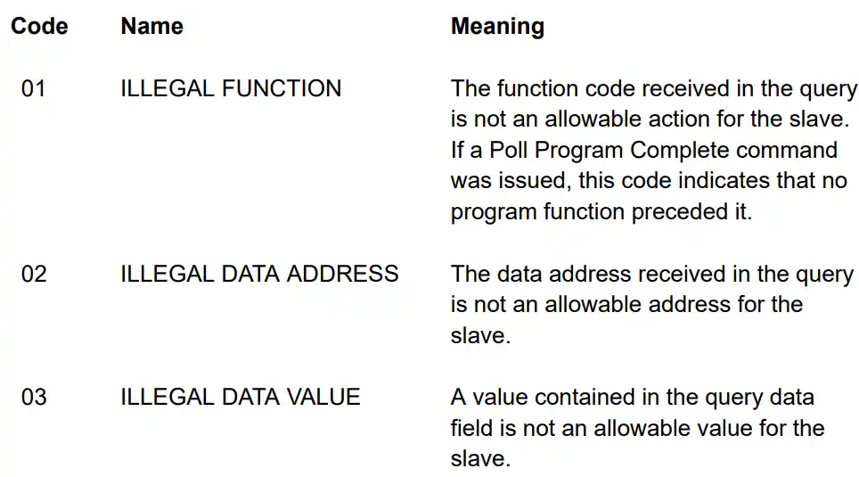
#define ILLEGAL_FUNCTION 0x01
#define ILLEGAL_DATA_ADDRESS 0x02
#define ILLEGAL_DATA_VALUE 0x03
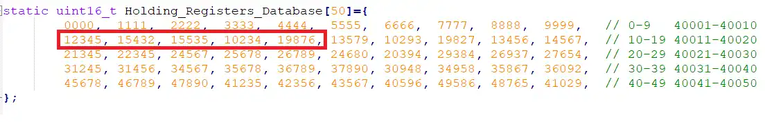
static uint16_t Holding_Registers_Database[50]={
0000, 1111, 2222, 3333, 4444, 5555, 6666, 7777, 8888, 9999, // 0-9 40001-40010
12345, 15432, 15535, 10234, 19876, 13579, 10293, 19827, 13456, 14567, // 10-19 40011-40020
21345, 22345, 24567, 25678, 26789, 24680, 20394, 29384, 26937, 27654, // 20-29 40021-40030
31245, 31456, 34567, 35678, 36789, 37890, 30948, 34958, 35867, 36092, // 30-39 40031-40040
45678, 46789, 47890, 41235, 42356, 43567, 40596, 49586, 48765, 41029, // 40-49 40041-40050
};I have defined the RxData and TxData buffers in the main file. The same buffers are defined in the modbusslave.c file but as extern variables.
The modbusslave.h file contains the slave ID, along with some exception codes. We will see the exception codes in a while.
I have also defines the database for the holding registers, which the master will request the data from.
SendData function
void sendData (uint8_t *data, int size)
{
  // we will calculate the CRC in this function itself
  uint16_t crc = crc16(data, size);
  data[size] = crc&0xFF;   // CRC LOW
  data[size+1] = (crc>>8)&0xFF;  // CRC HIGH

  HAL_UART_Transmit(&huart2, data, size+2, 1000);
}The sendData function is used to send the data to the master. I have made some changes in this function compared to the previous tutorials.
The CRC is now calculated within the function itself before the data is sent by the UART. The parameter size is the number of bytes the TxData buffer contains, before the function is called.
Inside the function we calculate the CRC, which is then stored in the next position is the data buffer. Finally the buffer is sent by the UART.
The modbus Exception function
As per the document provided by the modbus.org, the slave will send an exception when it can not handle the request.
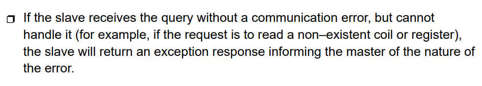
The exception consists of 2 fields.
- The Function code field, where the slave sets the MSB of the function code to 1. This makes the function code value in an exception response exactly 80 hexadecimal higher than the value would be for a normal response.
- The Data Field, where the slave returns an exception code in the data field. This defines the slave condition that caused the exception
There are different types of Exceptions, but we will be focused on main 3.
void modbusException (uint8_t exceptioncode)
{
	//| SLAVE_ID | FUNCTION_CODE | Exception code | CRC     |
	//| 1 BYTE   |  1 BYTE       |    1 BYTE      | 2 BYTES |

	TxData[0] = RxData[0];       // slave ID
	TxData[1] = RxData[1]|0x80;  // adding 1 to the MSB of the function code
	TxData[2] = exceptioncode;   // Load the Exception code
	sendData(TxData, 3);         // send Data... CRC will be calculated in the function
}- Here the first Byte of the response is the slave ID
- The we will add a ‘1’ to the MSB of the function code
- The third byte would be the the Exception code itself
- Finally we will send the Exception to the master.
Reading Holding Registers
uint8_t readHoldingRegs (void)
{
	uint16_t startAddr = ((RxData[2]<<8)|RxData[3]);  // start Register Address

	uint16_t numRegs = ((RxData[4]<<8)|RxData[5]);   // number to registers master has requested
	if ((numRegs<1)||(numRegs>125))  // maximum no. of Registers as per the PDF
	{
		modbusException (ILLEGAL_DATA_VALUE);  // send an exception
		return 0;
	}

	uint16_t endAddr = startAddr+numRegs-1;  // end Register
	if (endAddr>49)  // end Register can not be more than 49 as we only have record of 50 Registers in total
	{
		modbusException(ILLEGAL_DATA_ADDRESS);   // send an exception
		return 0;
}- Here we will first find out the Start Register address using the 3rd and 4th Bytes of the RxData buffer.
- Then we will calculate the number of Registers the master has requested using the 5th and 6th Bytes of the RxData Buffer
- If the master has requested more than 125 Registers, the slave will send an exception regarding ILLEGAL DATA VALUE.
- The 125 Registers limit is as per the modbus standard.
- Next we will calculate the address of the Last register. This is equal to the (start address + number of Registers -1).
- The -1 here is because the Register address starts from 0
- If the End Register is higher than 49, the slave will again send an Exception. I have set this limit to 49, as I have only defined 49 Register values in the database.
- If there is no exceptions so far, we will prepare the Tx buffer to send the Register values.
The slave response is shown below.
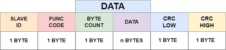
 // Prepare TxData buffer

 //| SLAVE_ID | FUNCTION_CODE | BYTE COUNT | DATA      | CRC     |
 //| 1 BYTE   |  1 BYTE       |  1 BYTE    | N*2 BYTES | 2 BYTES |

 TxData[0] = SLAVE_ID;  // slave ID
 TxData[1] = RxData[1];  // function code
 TxData[2] = numRegs*2;  // Byte count
 int indx = 3;  // we need to keep track of how many bytes has been stored in TxData Buffer

 for (int i=0; i<numRegs; i++)   // Load the actual data into TxData buffer
 {
   TxData[indx++] = (Holding_Registers_Database[startAddr]>>8)&0xFF;  // extract the higher byte
   TxData[indx++] = (Holding_Registers_Database[startAddr])&0xFF;   // extract the lower byte
   startAddr++;  // increment the register address
 }

 sendData(TxData, indx);  // send data... CRC will be calculated in the function itself
 return 1;   // success
}- Here the first Byte is the slave ID
- Then the second byte is the function code
- The third Byte will be the number of Bytes the slave is sending.
- This is equal to the number of Registers x 2, since each Register occupies 16 bits = 2 Bytes.
- Next we will start storing the data into the buffer.
- Here we will convert the 16 bit register value into the 2 Bytes data, with higher byte being extracted first.
- The 16 bit Register value is shifted to the right by 8 places to get the higher 8 bits.
- And the 16 bit Register value is again & with 0xFF to get the lower 8 bits.
- The indx variable keeps updating keeping the track of how many bytes has been stored in the TxData buffer.
- Finally we will send the data using the
sendDatafunction. The CRC will be calculated inside the function itself.
Input Registers
The process to Read the Input Registers is exactly the same. The only change there is in the definition of the database. I have defined the input Register Database as a constant array so that it can not be modified by the master.
static const uint16_t Input_Registers_Database[50]={
		0000,  1111,  2222,  3333,  4444,  5555,  6666,  7777,  8888,  9999,   // 0-9   40001-40010
		12345, 15432, 15535, 10234, 19876, 13579, 10293, 19827, 13456, 14567,  // 10-19 40011-40020
		21345, 22345, 24567, 25678, 26789, 24680, 20394, 29384, 26937, 27654,  // 20-29 40021-40030
		31245, 31456, 34567, 35678, 36789, 37890, 30948, 34958, 35867, 36092,  // 30-39 40031-40040
		45678, 46789, 47890, 41235, 42356, 43567, 40596, 49586, 48765, 41029,  // 40-49 40041-40050
};The master will send a query with the function code FC04, to read the Input Registers.
Result
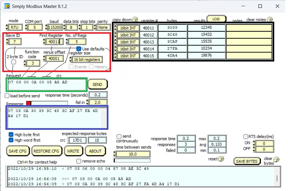
Above is the image of the master software sending the query and receiving the response from the slave device.
- Here the RED BOX contains the Slave ID (7), the start Address (40011) and the number of Registers to read (5)
- The GREEN BOX contains the query sent by the master in bytes format, based on the above configuration.
- The BLUE BOX is the response received by the master.
- The BLACK BOX contains the data received for the respective Resisters.
You can see the Register values are same as what we stored in the database as shown below.
STM32 Modbus RTU Tutorial Series

Modbus #1. STM32 Master Reads Holding and Input Registers

Modbus #2. STM32 Master Reads Coils and inputs

Modbus #3. STM32 Master Writes single Coil and Holding Register
Modbus #3.1 STM32 Master Writes Multiple Coils and Registers

Modbus #5. STM32 as Slave || Read Coils and Inputs

Modbus #6. STM32 as Slave || Write Registers

Modbus #7. STM32 as Slave || Writing Coils


please someone send me library?
The link to download the project is above the comment section. Can’t you see the download button ?
sorry i don’t know about download button. Thanks for reply 🙂
Hello, I’m using stm32f103c8t6 but i cant receive any data, its not work. can you help me?
The request is sent from the simply master, i checked from live expressions
and the data is also sent(I check it from TxData). But simply master dont show data.
I solved it.
Hi, how did you solve the problem? I have the same issue.
someone give me link of this library. pleasee.
The link to download the project is above the comment section. Can’t you see the download button ?
Hello admin,
I have question cum doubt,
first of all thankyou very Much for this simple and straight forward explanation for the topic,
In the topic “Modbus #4. STM32 as Slave || Read Holding and Input Registers”1: you created database of holding registers and reading it with 40001 starting register, where it is mentioned in the code i didn’t find,
2: if i want to define my addresses something like starting from 2000 to 2150 how would i define,
thankyou again for such informative blogs.
“you created database of holding registers and reading it with 40001 starting register, where it is mentioned in the code”
Well the database is not created at the address 40001. It will start from element 0 of the buffer. The way modbus communication works is, the function code (0x03) specifies that the master wants to read the holding register. Then the address 40001 sent by the master will be transmitted as 0, similarly, the address 40002 will be transmitted as 1, 40003 = 2 and so on.
thank you for valuable response, I got it.
Hi
i have problems
when i use timer intrupt with IDLE_IT
it doesnt work
i use stm32f103ret6
Try changing priorities of the interrupt in cubeMX
Hello! The above code does not work for me on the STM32G031 microcontroller.
In the file mine.с callback function void HAL_UARTEx_RxEventCallback(UART_HandleTypeDef *huart, uint16_t Size) , according to the documentation “Reception Event Callback (Rx event notification called after use of advanced reception service).” That is, the same HAL_UARTEx_ReceiveToIdle_IT(&huart2, RxData, 256) will cause an interrupt and this callback, but it is located inside it. How then will the data be received, please explain!
Ah, I understand. Before the endless loop, you call the receive function. Sorry for disturbing you!
Hi, I have a doubt how to store the in built sensor values and send it to master when the request is raised
you can just update respective holding register with the sensor’s value.
HoldingRegisterDatabase[13] = value;
Later the master can just request this register’s value to get the data.
Hi, I have the same question as Maryam. Can you explain how to modify the project in order to use SimplyModbus Master with STM32 as a slave with RS485 module? I have changed the sendData function in order to set and reset TX_EN pin, but I have no clue how to activate it before receiving data from simplymodbus master software.
Best regards
you don’t modify it. When the TXEN pin is low, the mode is set to receive mode. This is how we were receiving the data when the STM32 was set to master mode.
Thank you for your anwer. I checked the module datasheet and thought the same way. For now, I changed only sendData function in order to set and reset TX_EN pin and updated huart2 to huart1 in main.c and modbusSlave.c which I’m using, the rest of the code is the same as in the tutorial. There’s still no communication between STM and SimplyModbus.
Are you able to get the data??
When we use STM32 as slave and “simplymodbus Master” as Master, how the pins “RO” and “DI” are controlled for sending and receiving data to STM32
and also “RE” and “DE”
Hi, may you describe when stm32 is as slave, How the RS485 is controlled???
I sent data to STM32 by “simplymodebus Master” but it didn’t receive any data from stm32
check the answer above