Interface SPI LCD with ESP32
In this tutorial you will learn how to connect and program an SPI LCD(ILI9341) with ESP32 using Espressif IDE. This tutorial includes wiring, code, and display tips for your embedded projects. The project is available to download at the end of this post.
This is the 10th tutorial in the ESP32 series using the Espressif-IDE and 1st in the mini series covering SPI-LCDs in ESP32. In this mini series we will first see how to interface the SPI based displays with ESP32 using the ESP32’s built in LCD library. Then we will implement the LVGL functionality to our project. Finally we will also implement the touch function in the displays that supports it.
VIDEO TUTORIAL
You can check the video to see the complete explanation and working of this project.
Introducing ILI9341 Display
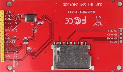
The ILI9341 is a popular 2.4″ to 3.2″ TFT LCD display controller that supports 240×320 resolution and SPI interface. It’s often paired with the XPT2046 touch controller, enabling capacitive or resistive touch input. Together, they provide an affordable and efficient solution for graphical user interfaces in embedded systems like STM32 and ESP32.
Here are the important features of the ILI9341 Display:
- 240×320 pixel resolution with 262K color support
- SPI communication for both display (ILI9341) and touch (XPT2046)
- Integrated resistive touch support via XPT2046
- Compact size and low power consumption, ideal for embedded GUIs
WIRING DIAGRAM
Below is the image showing the connection between ESP32 and ILI9341.
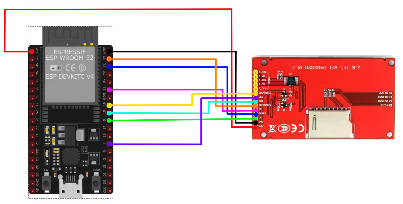
I am going to use the VSPI_HOST for the SPI. The SPI pins in the image above are defined according to it. You can check the SPI tutorial to know more about the available instances on ESP32.
| Pin Name | Function | Connected to |
|---|---|---|
| VCC | Power Supply (3.3V) | 3.3V |
| GND | Ground | GND |
| SDI / DI (MOSI) | SPI Data Input | GPIO23 |
| SDO / DO (MISO) | SPI Data Output | GPIO19 |
| SCK | SPI Clock | GPIO18 |
| DC / RS | Data/Command Select | GPIO21 |
| RESET | Reset Pin | GPIO22 |
| LCD_CS | Chip Select (LCD) | GPIO5 |
| LED | Backlight Control | GPIO4 / 3.3V |
INITIAL SETUP
We will first create a basic project in the Espressif IDE.
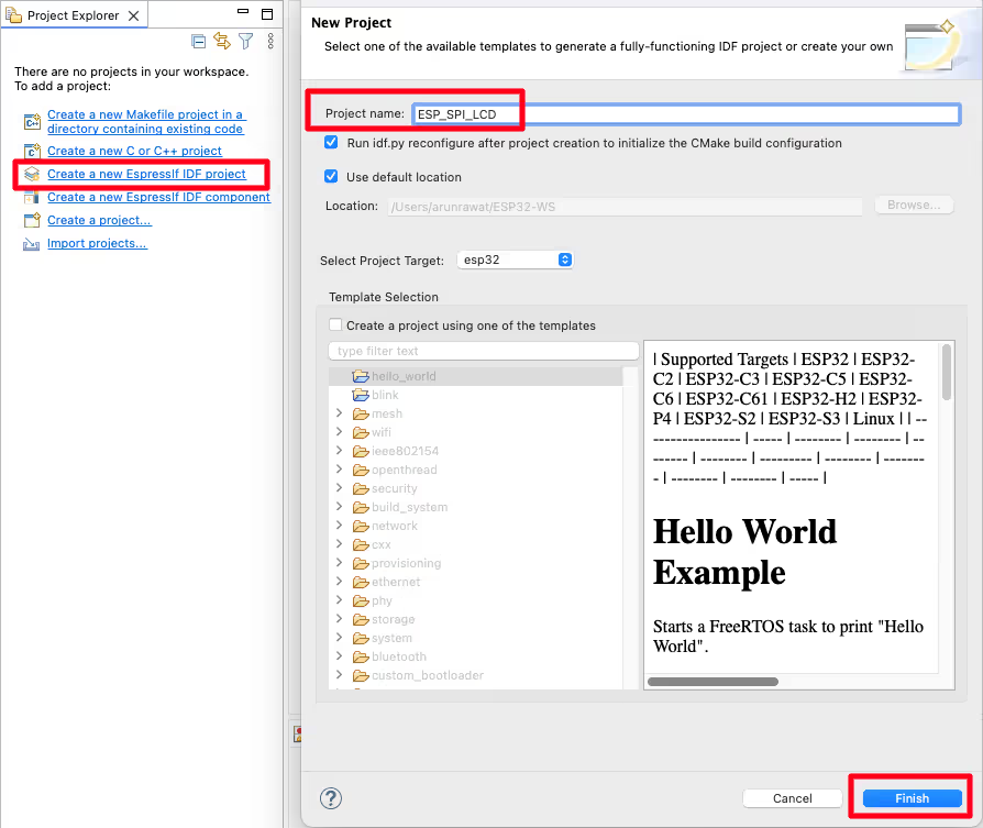
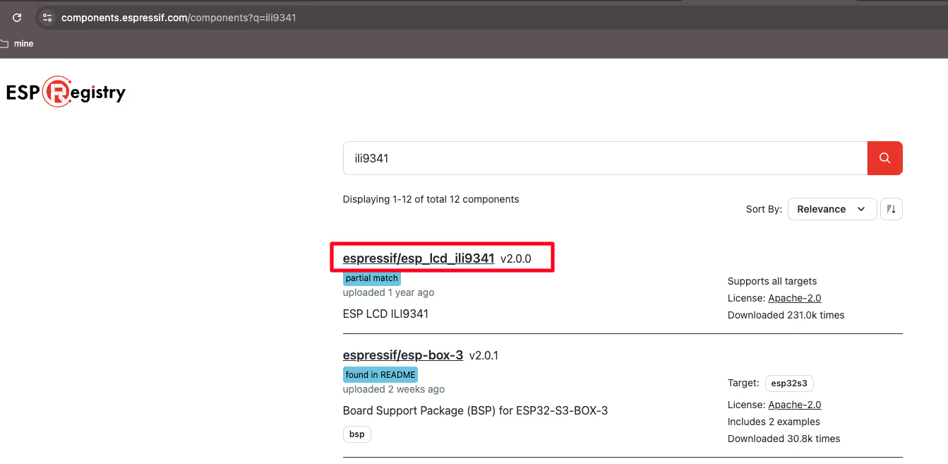
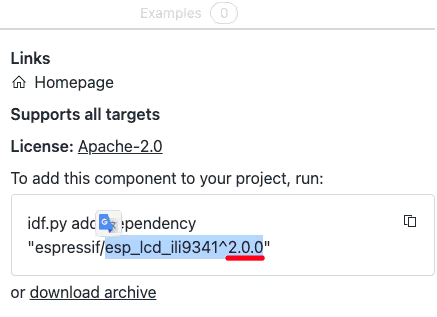
Now go to the https://components.espressif.com/ and search for the display controller (ILI9341 in this case). You will get a lot of results, but make sure to open one with esp_lcd_**** as shown in the image below.
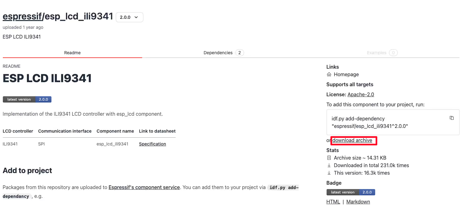
Download the component archive and extract it.
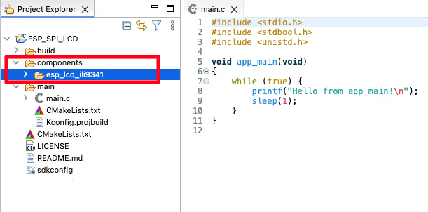
Now copy this extracted folder inside the project folder. I have created a new folder (components), where I will place all the components used in the project.
We need to link this component to our project. To do so, we will create a new file (idf_component.yml) inside the main folder.
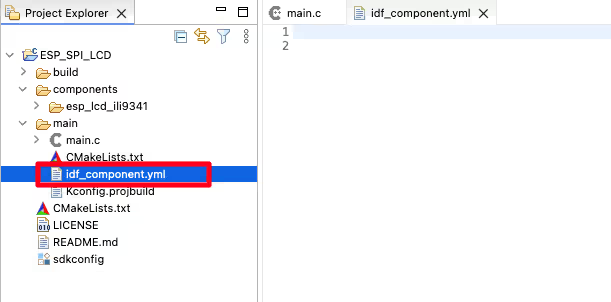
Now add the dependency of the lcd component in this file.
dependencies:
esp_lcd_ili9341: "^2.0.0"Note:- make sure there is only single space in the 2nd line.
Here the 2.0.0 is the component library version and it can be found in the component page itself.
THE CODE
Inclusions
First we need to include the necessary files.
#include <stdio.h>
#include <stdbool.h>
#include <unistd.h>
#include "driver/gpio.h"
#include "esp_lcd_ili9341.h"
#include "esp_lcd_panel_commands.h"
#include "esp_lcd_panel_dev.h"
#include "esp_lcd_panel_interface.h"
#include "esp_lcd_panel_io.h"
#include "esp_lcd_panel_ops.h"
#include "esp_lcd_panel_vendor.h"
#include "hal/gpio_types.h"
#include "hal/spi_types.h"Here I have included the esp_lcd_ili9341.h file from the component. The rest of the inclusions starting with esp_lcd_panel_** are needed for the LCD operations. All of them might not be needed, but I have included all available.
Definitions
Now we will define the pins used in this project.
#define LCD_HOST	VSPI_HOST
#define PIN_NUM_SCLK    18
#define PIN_NUM_MOSI    23
#define PIN_NUM_MISO    19
#define PIN_NUM_LCD_CS  5
#define PIN_NUM_BKL     4
#define PIN_NUM_RST     22
#define PIN_NUM_LCD_DC 21As I mentioned earlier, I am going to use the VSPI_HOST for the LCD. The pins are defined according to the connection diagram shown in the beginning of the article.
Next define some LCD related constants we will be using.
#define LCD_H_RES	240
#define LCD_V_RES	320
#define LCD_PIXEL_CLOCK_HZ	20*1000*1000
#define LCD_CMD_BITS	8
#define LCD_PARAM_BITS 8H_RES and V_RES are the Horizontal and Vertical resolution of the display. The LCD_PIXEL_CLOCK_HZ is the Piexl clock frequency in Hertz. The pixel clock determines how quickly the ESP32 can send data to update the LEDs, thus controlling the refresh rate and animation speed. I have set it to 20MHz.
LCD_CMD_BITS and LCD_PARAM_BITS sets the bit width of the command and parameter that recognised by the LCD controller chip. This is chip specific, and ILI9341 uses 8 bits for it.
Display Driver
We will create a separate function to initialise the display driver. We just need to follow the steps mentioned in this guide.
static void display_init (void)
{
	gpio_set_direction(PIN_NUM_BKL, GPIO_MODE_OUTPUT);
gpio_set_level(PIN_NUM_BKL, 1);First of all I am setting the LCD backlight pin as output and the level of this pin is set to high. If you are connecting the backlight pin to 3.3V, you do not need to do this.
STEP 1
Create a SPI bus.
       spi_bus_config_t buscfg = {
    .sclk_io_num = PIN_NUM_SCLK,
    .mosi_io_num = PIN_NUM_MOSI,
    .miso_io_num = PIN_NUM_MISO,
    .quadwp_io_num = -1,
    .quadhd_io_num = -1,
    .max_transfer_sz = LCD_H_RES * 80 * sizeof(uint16_t), // transfer 80 lines of pixels (assume pixel is RGB565) at most in one SPI transaction
};
ESP_ERROR_CHECK(spi_bus_initialize(LCD_HOST, &buscfg, SPI_DMA_CH_AUTO)); // Enable the DMA featureHere we will simply define the CLK, MISO and MOSI pins for the SPI. Since we are not using QUADSPI, the respective pins are set to -1. The maximum transfer size in one SPI transaction is set to LCD_H_RES * 80 * 2 bytes. Basically we can transfer upto 80 lines data in one transaction.
STEP 2
Allocate an LCD IO device handle from the SPI bus.
esp_lcd_panel_io_spi_config_t io_config = {
    .dc_gpio_num = PIN_NUM_LCD_DC,
    .cs_gpio_num = PIN_NUM_LCD_CS,
    .pclk_hz = LCD_PIXEL_CLOCK_HZ,
    .lcd_cmd_bits = LCD_CMD_BITS,
    .lcd_param_bits = LCD_PARAM_BITS,
    .spi_mode = 0,
    .trans_queue_depth = 10,
};
// Attach the LCD to the SPI bus
ESP_ERROR_CHECK(esp_lcd_new_panel_io_spi((esp_lcd_spi_bus_handle_t)LCD_HOST, &io_config, &io_handle));Here we will allocate the CS and DC pins along with the Pixel Clock and command and parameter bits. The SPI Mode is set to Mode 0 and the queue depth is set to 10. This is basically the depth of the SPI transaction queue.
STEP 3
Install the LCD controller driver. The LCD controller driver is responsible for sending the commands and parameters to the LCD controller chip.
esp_lcd_panel_dev_config_t panel_config = {
    .reset_gpio_num = PIN_NUM_RST,
    .rgb_ele_order = LCD_RGB_ELEMENT_ORDER_BGR,
    .bits_per_pixel = 16,
};
// Create LCD panel handle for ILI9341, with the SPI IO device handle
ESP_ERROR_CHECK(esp_lcd_new_panel_ili9341(io_handle, &panel_config, &lcd_panel_handle));The rgb_ele_order sets the R-G-B element order of each color data. It is set to BGR in case of ILI9341. If there is some colour related issue, you can set it back to RGB.
bits_per_pixel sets the bit width of the pixel color data. The LCD driver uses this value to calculate the number of bytes to send to the LCD controller chip. ILI9341 uses RGB565, which requires 2 bytes per pixel, hence it is set to 16 bits.
The function esp_lcd_new_panel_ili9341 will attach the above configuration to the ILI9341. This function is present in the component library we downloaded. In fact a similar function is present in each LCD component library. So say for example in case of ST7735, the function will change to esp_lcd_new_panel_st7735.
STEP 4
Perform the LCD IO Operations.
So far we have only attached the LCD to the SPI. Now we will perform the initialization for the display.
esp_lcd_panel_reset(lcd_panel_handle);
esp_lcd_panel_init(lcd_panel_handle);
esp_lcd_panel_disp_on_off(lcd_panel_handle, true);
}Here we will first reset the LCD. The initialise it and finally turn the display on.
The main function
Inside the main function, we will first initialise the display and then draw some bitmap on it. This display driver is created to be used with libraries like LVGL, hence it does not provide many functions to draw on display. Therefore we only have a function to draw the bitmap on the display.
void app_main(void)
{
    display_init();
    esp_lcd_panel_swap_xy(lcd_panel_handle, true);
    esp_lcd_panel_draw_bitmap(lcd_panel_handle, 0, 0, 100, 50, hello_map);
    while (true) {
        sleep(1);
    }
}After initialising the display, I am using the swap function to swap the X and Y Axes of the display. Basically you can use a combination of esp_lcd_panel_swap_xy and esp_lcd_panel_mirror function to rotate the display.
I am using a small bitmap of resolution 100×50. The drawing starts at the beginning of the display (0,0). The bitmap array is defined as hello_map, which you can find in the final project itself.
Any other SPI display can be interfaced using the same method. There are only few things which needs to be taken care of.
- The function to Create LCD panel handle,
esp_lcd_new_panel_ili9341will change according to the display. - The
rgb_ele_ordermight change based on the display color endianness. You can try keeping the same order, but if the colours are different than the actual image, change this order. There are only 2 orders supported, RGB and BGR. - The
bits_per_pixelmight change based on the display. Check if the display controller supports RGB565(16 bits) or RGB888(24 bits) or XRGB8888(32 bits). - The
LCD_H_RESandLCD_V_RESwill definitely change based on the display size. - The
LCD_CMD_BITSandLCD_PARAM_BITSmight change based on the display. Do check the datasheet of the display controller.
RESULT
Below is the image showing the bitmap printed on the display.
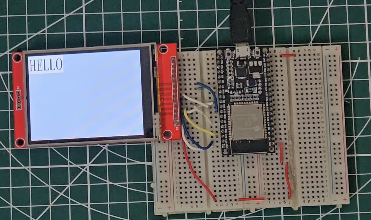
The display is rotated because of the sawp function I used before drawing the bitmap.
PROJECT DOWNLOAD

