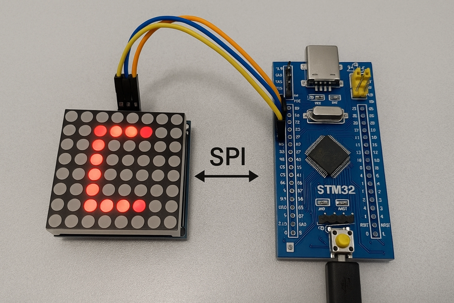
Learn to interface an 8×8 LED dot matrix with STM32 using SPI and MAX7219. his tutorial Covers initialization, wiring, and code walkthrough. The project can be downloaded at the end of this post.
This is the 1st tutorial in a mini series covering the Dot Matrix Module with STM32 via SPI. In this tutorial we are going to cover the initial part, i.e. initialise the display and display some characters on a single 8×8 dot matrix. Scrolling, cascading and other features will be covered in upcoming tutorial.
The MAX7219 ICs are originally designed to interface the 7-segment displays. But when they are used for the Dot Matrix displays, there no standards followed for ROWs and Columns. Therefore there are a lot of types of dot matrix displays out there. The most common ones are FC-16, Generic, ICStation and Parola. Each type of hardware support a different set of library.
But in this tutorial we will not focus on the hardware type. Instead we will first do some trial and error to get the correct configuration for the display we have. Then we will write the rest of the library ourselves.
VIDEO TUTORIAL
You can check the video to see the complete explanation and working of this project.
Introducing Dot Matrix Module
The dot matrix module with MAX7219 is a compact display unit that uses an 8×8 LED matrix controlled by the MAX7219 driver chip. It simplifies the process of controlling multiple LEDs by handling all the multiplexing and current regulation internally. Commonly used in electronics projects for scrolling text, symbols, or simple animations, it communicates with microcontrollers using the SPI protocol, making it efficient and easy to integrate with platforms like STM32, Arduino, and ESP32.
Some of the important features of Dot Matrix Module are:
- Built-in MAX7219 Driver:
Handles LED scanning, multiplexing, and current control, reducing microcontroller workload. - SPI Interface:
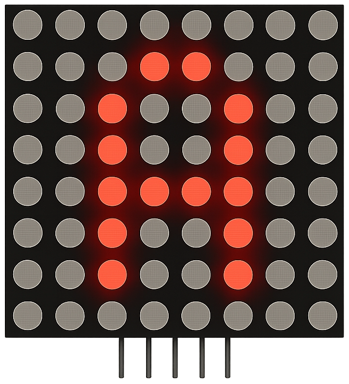
Communicates efficiently over a 3-wire SPI protocol (DIN, CLK, CS), supporting daisy chaining of multiple modules. - 8×8 LED Display:
Offers 64 individually addressable LEDs in a matrix format, ideal for characters and patterns. - Cascadable Design:
Multiple modules can be connected in series to create larger displays for scrolling text or graphics.
CUBEMX CONFIGURATION
Clock Configuration
Below is the image showing the clock configuration.
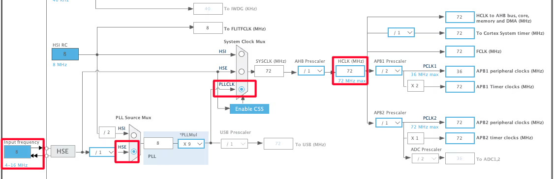
The STM32F103 is clocked by the external 8MHz crystal. The system is running at maximum 72MHz clock.
SPI Configuration
Below is the image showing the SPI configuration.
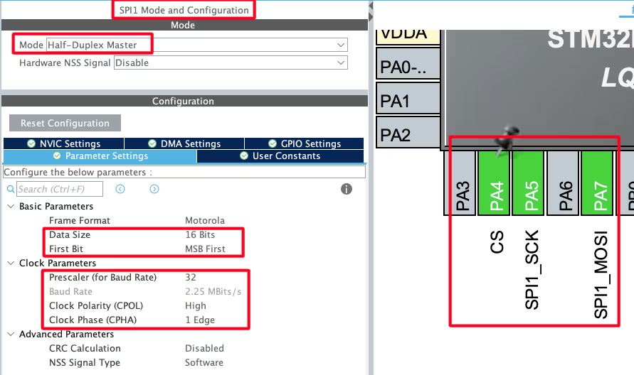
I am using the SPI1 for this tutorial. The SPI is configured in the Half Duplex Mode. This is because we only need the SPI to send the data to the display, but not receive anything from it.
- The Data Size is set to 16 bits with MSV first. This is because the MAX7219 expects the data in 16 bit format.
- There is no requirement for the Baud Rate, so I have configured it around 2 Mbps.
- The Clock Polarity is set to HIGH and Clock Phase is set to 1 Edge. This is important and as per the MAX7129 datasheet, the CPOL must be 1.
The pins PA5 and PA7 are configured as the SCK and MOSI pins. We will also set the pin PA4 as output and rename it to CS.
WIRING DIAGRAM
Below is the image showing the connection between STM32F103 and Dot Matrix Display.
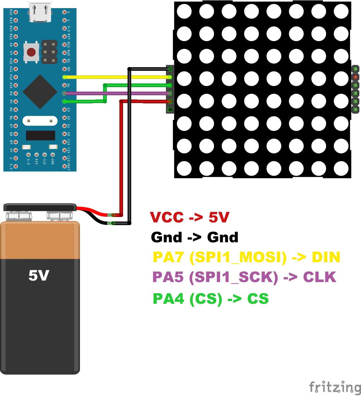
As you can see in the image above,
| STM32 Pin | SPI Function | Connected to Device Pin |
|---|---|---|
| PA5 | SPI1_SCK | CLK |
| PA7 | SPI1_MOSI | DIN |
| PA4 | CS | CS |
The device is powered with 5V supply from a battery. You must use some external power source for these type of displays. There are a lot of LEDs connected, and when they all are turned ON, they consume a lot of current. This might damage the MCU. Therefor use some external 5V power supply for these type of displays.
THE CODE
Below is the image showing the Register map of the MAX7219.
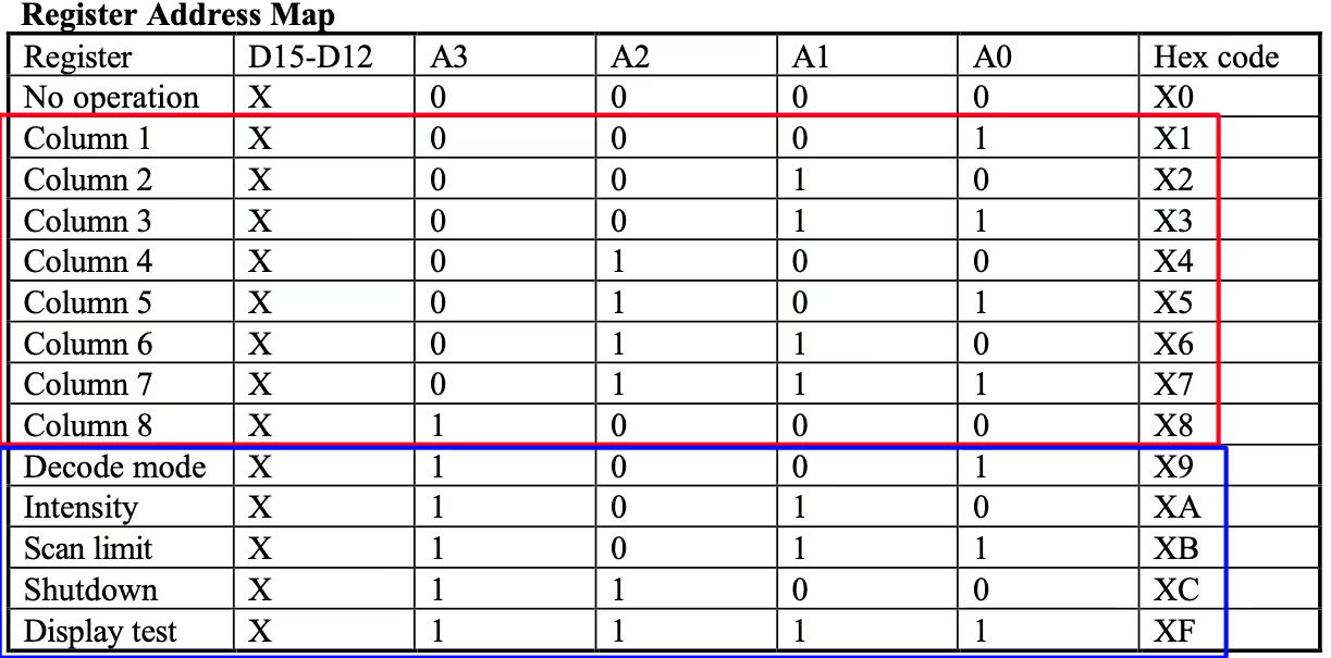
The registers address from 0x01 to 0x08 are assigned for the columns. These registers are responsible for displaying the data on the respective column.
The Registers from 0x09 to 0x0F are used for initialising the Display. We will take a look at these Registers first.
Also we will define a new function to send the 16 bit data via the SPI.
void max7219_write (uint8_t Addr, uint8_t data)
{
	uint16_t writeData = (Addr<<8)|data;
	HAL_GPIO_WritePin(CS_GPIO_Port, CS_Pin, 0);  // enable slave
	HAL_SPI_Transmit(&hspi1, (uint8_t *)&writeData, 1, 100);
	HAL_GPIO_WritePin(CS_GPIO_Port, CS_Pin, 1);  // disable slave
}The parameter of the function max7219_write are:
@Addr is the register address where we want to write the data
@data is the data byte itself.
- Inside this function, we will first combine both Register Address and the data byte in a single 16 bit variable.
- Then pull the CS pin LOW to enable the slave.
- Transmit the 16 bit data via the SPI. The function
HAL_SPI_Transmitexpects a pointer to the 8bit unsigned array, so we will typecast the address of the 16bit variable. - Pull the CS pin HIGH to disable the slave.
Initialisation
As I mentioned, we need to initialise the display using the Registers from 0x09 to 0x0F. Below is the initialisation function.
void matrixInit (void)
{
	max7219_write(0x09, 0);  // no decoding
	max7219_write(0x0a, 0x01);  // 3/32 intensity
	max7219_write(0x0B, 0x07);  // scan all 7 columns
	max7219_write(0x0C, 0x01);  // normal operation
	max7219_write(0x0F, 0);     // No display test
}The Decode Mode register (0x09) is used to enable the decode mode for the digits in the 7 segment display. We will not use this mode for the dot matrix display, so disable the Decode mode by writing 0 to this Register.
The Intensity Register (0x0A) is used to set the brightness of the LEDs. Below is the Register details.
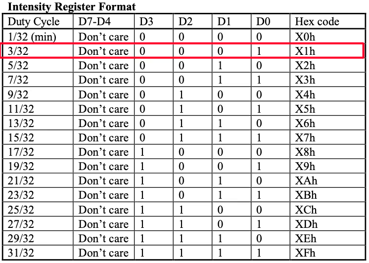
The more the Duty Cycle, the brighter the LEDs are, and the more current they will consume. So the value in this register is a tradeoff between the brightness and current consumption. I am keeping the brightness towards the lower side, 3/32 Duty.
The Scan Limit Register (0x0B) configures how many columns we want to enable. Below is the image showing the details of the register.
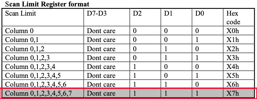
Our 8×8 display has 8 Rows and 8 Columns. Therefore we want to enable all the 8 columns and hence the value in this register will be 7.
The Shutdown register (0x0C) control whether the device should be in the Shutdown Mode or the Normal Operation Mode.
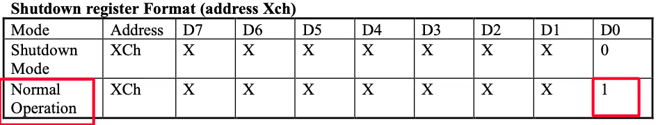
We want the device to be in the Normal Operation Mode, so write the value 1 to this Register.
The Display Test Register (0x0F) is used to test the 7-segment display. We will keep this test disabled, so write 0 to this Register as well.
Write Data
As I mentioned, we will do some trial and error to figure out the correct configuration for our display. Also keep in mind that the frame of reference is how you will see the pictures. We should not worry about how the display should have been, instead we will try to make it work in the way we are seeing it.
Inside the main function write the code as follows:
int main ()
{
  ....
  matrixInit();
  for (int i=1; i<=8; i++)
  {
     max7219_write(i, i);
  }
  while (1)
  {}
}Here we will initialise the display first, and then write the data to all the 8 columns in a for loop. The data is also incrementing with the columns. So Col1 will have the data 1, and Col8 will have the data 8.
Below is the output that I got with this code.
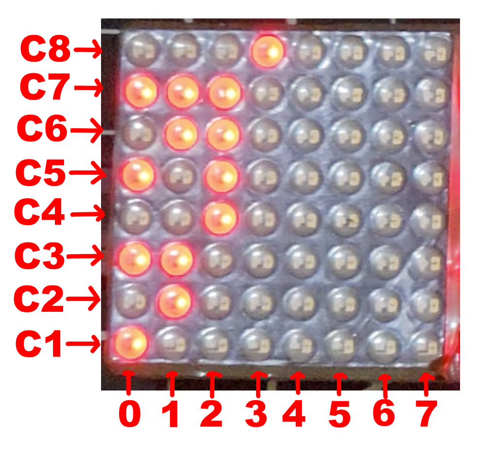
You can see in the image above that the bottommost column has only the first LED turned ON. We sent the data 0x01 to the COL1, hence the COL1 is at the bottom. Then the pattern in which the LEDs are turned ON increases as the binary format.
Based on the display output, we can conclude 2 things:
- The columns are increasing from bottom to top.
- The data is printed in the Little Endian Form. You can see that the data 0x01 in COL1 is printed in a way that the 1 is sent first, followed by the 0.
Configure a tool
We can write the library for all the characters ourselves, but it would be very time consuming. It is better to have a tool, that can generate the data bytes based on the character we draw.
I am sure there are a lot of tools available for it, and here is one that I found helpful, https://dotmatrixtool.com/#
We will configure this tool according to our display setup. Once done, we can generate the data for any character we want.
Once you open the tool, you will get the choices as shown below.
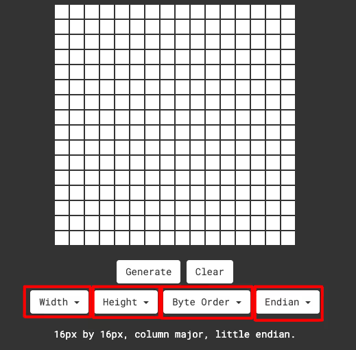
Out of the above mentioned 4 choices, we know the 3 of them. The display width, height and endianness. But let’s assume that we don’t know Endianness also, still we know the width and height are 8 x 8.
I will first start by wrong setup and then we will figure out the correct one together. To find out the correct configuration, we will do the Reverse Engineering. We will enable the LEDs as how we got the output during our test. Whatever configuration gives us the correct data set, is the right one.
Column Major & Big Endian
Below is the output based on the configuration.
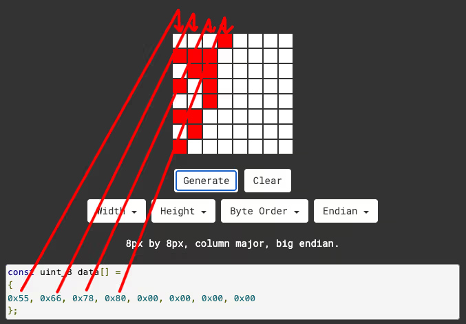
As you can see in the image above, the data in the output is arranged according to the columns. This is fine according to the tool, but for us, the Rows are actually the columns. So Column major is definitely not the configuration we are looking for.
Row Major & Big Endian
Below is the output based on the configuration.
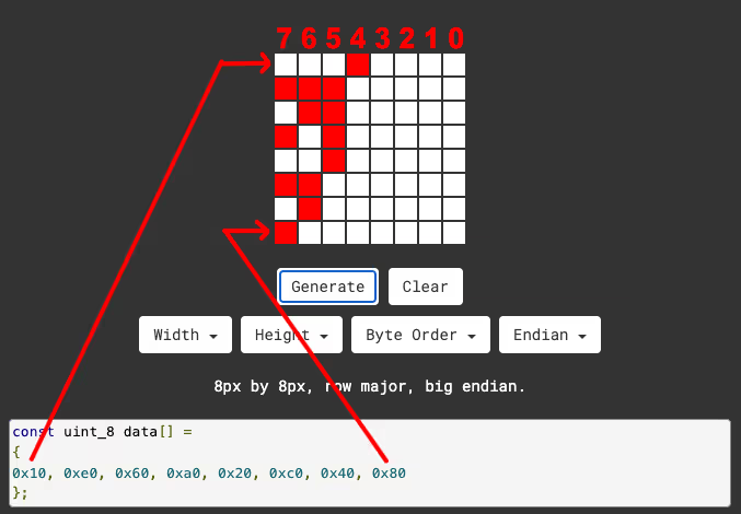
As you can see in the image above, the data is now arranged in the Row form, but there are still 2 issues.
- The first Column is the Top Row. As per our setup, it should have been the bottommost Row.
- The Data is Big Endian. In the last row, only the first LED is ON and the data is 0x80. It should have been 0x01.
Row Major & Little Endian
Below is the output based on the configuration.
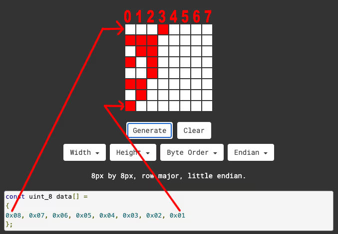
As you can see in the image above, the Endianness issue has been resolved. Now the last Row, where only the first LED is ON, outputs the data 0x01.
We still have the issue of the Columns being increasing from top to bottom, but we will solve this one in the code itself. We simply need to reverse the order in which the data is sent. Basically we need to send the last Byte to the COL1, the second last to the COL2 and so on.
Print a character
Let’s say that I want to print a smiley character on the display. Below is the image showing the design and data on the tool.
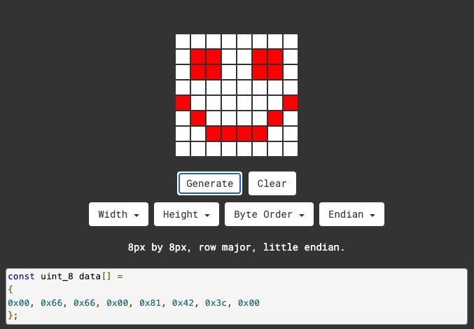
We will first copy the data output and paste it in our code.
const uint8_t data[] =
{
  0x00, 0x66, 0x66, 0x00, 0x81, 0x42, 0x3c, 0x00
};

int main ()
{
  ....
  matrixInit();
  for (int i=1; i<=8; i++)
  {
     max7219_write(i, data[8-i]);
  }
  while (1)
  {}
}In the main function we will initialise the display first, and then send all the data bytes to the columns in a for loop. The data is sent in a way that the COL1 gets the data[7], COL2 gets data[6] and COL8 gets data[0].
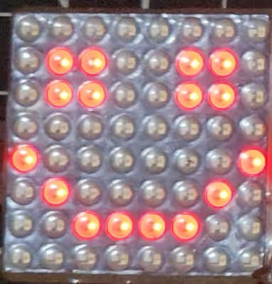
Below is the image showing the output of the above code.
The main function
I have defined an array of numbers which contain the data bytes for displaying the respective number.
const uint8_t charData[][8] = {
		{0x00, 0x1c, 0x22, 0x22, 0x22, 0x22, 0x1c, 0x00},  // 0
		{0x08, 0x0c, 0x08, 0x08, 0x08, 0x08, 0x3e, 0x00},  // 1
		{0x1c, 0x22, 0x20, 0x18, 0x04, 0x02, 0x3e, 0x00},  // 2
		{0x1c, 0x22, 0x20, 0x1c, 0x20, 0x22, 0x1c, 0x00},  // 3
		{0x20, 0x30, 0x28, 0x24, 0x7c, 0x20, 0x20, 0x00},  // 4
		{0x3e, 0x02, 0x1e, 0x20, 0x20, 0x20, 0x1e, 0x00},  // 5
		{0x18, 0x04, 0x02, 0x1e, 0x22, 0x22, 0x1c, 0x00},  // 6
		{0x3e, 0x20, 0x10, 0x08, 0x04, 0x04, 0x04, 0x00},  // 7
		{0x1c, 0x22, 0x22, 0x1c, 0x22, 0x22, 0x1c, 0x00},  // 8
		{0x1c, 0x22, 0x22, 0x3c, 0x20, 0x10, 0x0c, 0x00},  // 9
};The charData is a matrix with some Rows and 8 columns. The Rows here are arranged as per the number. For example, the ROW0 contains the data for the number 0, ROW2 contains the data for the number 2 and ROW9 contains the data for the number 9.
Now we will write another function, which can display the provided number.
void matrixData(int num)
{
	for (int i=1; i<=8; i++)
	{
		max7219_write(i, charData[num][8-i]);
	}
}The parameter of this function is the number that we want to print on the display.
Inside this function, we will call the function max7219_write to send the data to all the columns. As I already mentioned, the Rows of the matrix charData are arranges according to the numbers, so we will simply pass the num parameter to the Row element of the matrix. The columns contains the data for the respective number, so we will send the data bytes in the descending order.
Inside the main function, we will print the number from 0 to 9, every 500ms.
int main ()
{
  ....
  matrixInit();
  while (1)
  {
    for (int i=0; i<10; i++)
    {
      matrixData(i);
      HAL_Delay(500);
    }
    HAL_Delay(1000);
  }
}RESULT
Below is the gif showing the output of the above code.

You can see the numbers from 0 to 9 are printing every 500ms.
Note that I still don’t know the hardware type I have for the dot matrix display, but we were able to print characters and numbers without any issue. You can watch the video below to see more detailed working.
PROJECT DOWNLOAD


well done sir, I used your code to get into the STM32 world. Thank you.