Interfacing BME280 Sensor with STM32 using I2C
The BME280 sensor is a powerful environmental sensor that can measure temperature, pressure, and humidity with high accuracy. It is widely used in weather stations, IoT projects, and home automation systems. In this guide, we will learn how to interface the BME280 with an STM32 microcontroller using the I2C communication protocol. You will see how to configure the sensor registers, read raw data, and apply compensation formulas to get accurate real-world values. By the end of this tutorial, you will be able to integrate the BME280 into your STM32 projects with ease.
BME280 STM32 Video Tutorial
While the written guide below provides all the details and code for reference, sometimes a visual demonstration can make all the difference. I’ve created a complete video walkthrough that runs through the entire process in real-time. Follow the written steps here while watching the implementation in the video to solidify your understanding and catch any subtle details
Watch the Video- Introducing the BME280 Sensor
- STM32 BME280 Project Requirements
- STM32 BME280 sensor Wiring Diagram
- Configuring the BME280 Registers
- Reading Raw Data from the BME280 Sensor
- Converting BME280 Raw Data to Real Values
- Configuring the BME280 Sensor for Measurement
- BME280 Sensor STM32 HAL main function
- Result of Interfacing BME280 with STM32
- PROJECT DOWNLOAD
- STM32 BME280 Sensor Project FAQs
Introducing the BME280 Sensor
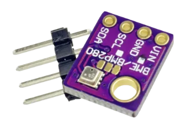
The BME280 is a digital environmental sensor developed by Bosch, designed to measure temperature, pressure, and humidity with high precision. It combines three sensors in a single compact package, making it an excellent choice for weather monitoring, IoT applications, and smart home systems. The sensor communicates with microcontrollers via I2C or SPI, which makes it highly flexible for embedded projects such as those using STM32.
Features and Specifications
- Supply Voltage: 1.71V – 3.6V
- Current Consumption: Extremely low, suitable for battery-powered devices
- Communication Interfaces: I2C (up to 3.4 MHz) and SPI (up to 10 MHz)
- Temperature Range: -40 °C to +85 °C
- Pressure Range: 300 hPa to 1100 hPa (altitude up to ~9000 m)
- Humidity Range: 0% to 100% relative humidity
- Resolution: Up to 20-bit for temperature/pressure, 16-bit for humidity
- Package: Compact 2.5 × 2.5 × 0.93 mm LGA package
These specifications make the BME280 an ideal sensor for weather stations, indoor climate monitoring, and IoT edge devices.
Operating Modes of BME280
The BME280 supports three operating modes, giving flexibility depending on the use case:
- Sleep Mode: The sensor remains inactive, consuming the least power. Registers can still be read and written.
- Forced Mode: The sensor performs a single measurement of temperature, pressure, and humidity, then returns to sleep mode automatically. This is useful when you need occasional readings.
- Normal Mode: The sensor continuously measures data in the background with configurable standby intervals. This mode is best for applications requiring real-time updates.
Oversampling and Resolution
To improve accuracy, the BME280 uses oversampling for temperature, pressure, and humidity measurements. Oversampling means the sensor takes multiple measurements and averages them, which increases resolution but also increases power usage and measurement time.
- Humidity: Always provides a 16-bit output.
- Temperature and Pressure: Can provide up to 20-bit resolution when the IIR filter is enabled.
- Without IIR filter: Resolution depends on the oversampling setting (e.g., oversampling ×1 → 16-bit, oversampling ×16 → 20-bit).
Choosing the right oversampling level allows you to balance between measurement precision, speed, and power consumption.
STM32 BME280 Project Requirements
I am going to use the STM32F103 Dev board along with the BME280 Sensor Module for this project.
We’ve added affiliate links for your convenience — if you purchase through these links, it helps support our work at no extra cost to you.
STM32 BME280 sensor Wiring Diagram
The image below shows how to connect the BME280 sensor to the STM32 microcontroller using the I2C interface.
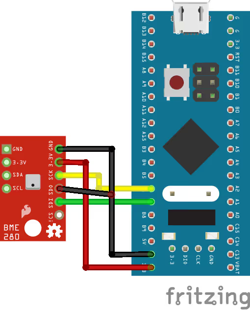
The wiring is quite simple. Connect SCK to PB6 (SCL) and SDI to PB7 (SDA). Power the BME280 with 3.3V.
Note: The SDO pin must be connected to GND when using the I2C interface. This is important, as it defines the I2C address of the sensor.
| BME280 Pin | STM32 Pin | Function |
|---|---|---|
| VCC | 3.3V | Power Supply |
| GND | GND | Ground |
| SCK | PB6 | I2C Clock (SCL) |
| SDI | PB7 | I2C Data (SDA) |
| SDO | GND | I2C Address Select |
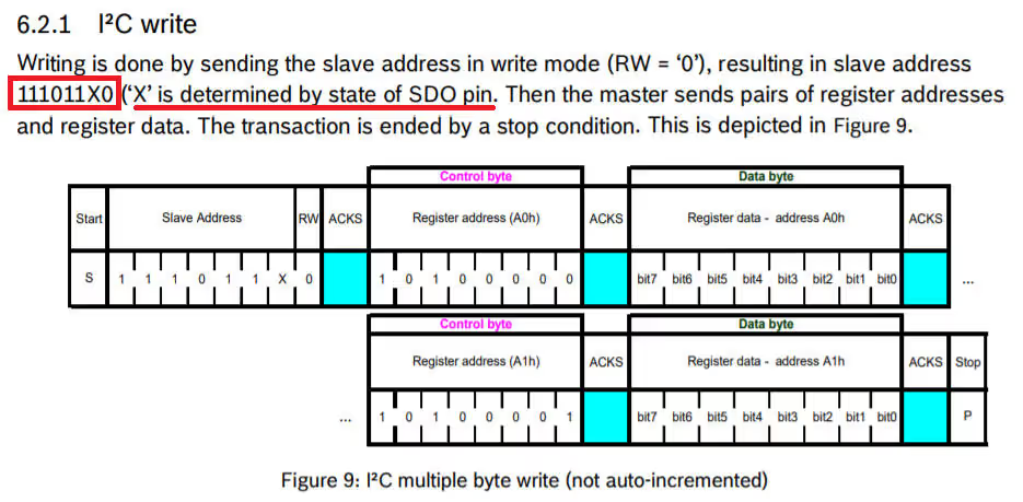
As mentioned in the datasheet, the address of the BME280 is 111011X0 and here X is determined by the SDO pin. Since I have connected it to the ground, the address in my case would be 11101100 that is 0xEC.
Configuring the BME280 Registers
Before reading meaningful data from the BME280, we must configure the sensor properly. First, we set up oversampling, filter options, standby time, and operating mode. The BME280 provides flexible settings for humidity, pressure, and temperature measurements. For each parameter, we can enable, skip, or oversample it to achieve the right balance between accuracy, speed, and power consumption.
Humidity Measurement (CTRL_HUM Register – osrs_h[2:0])
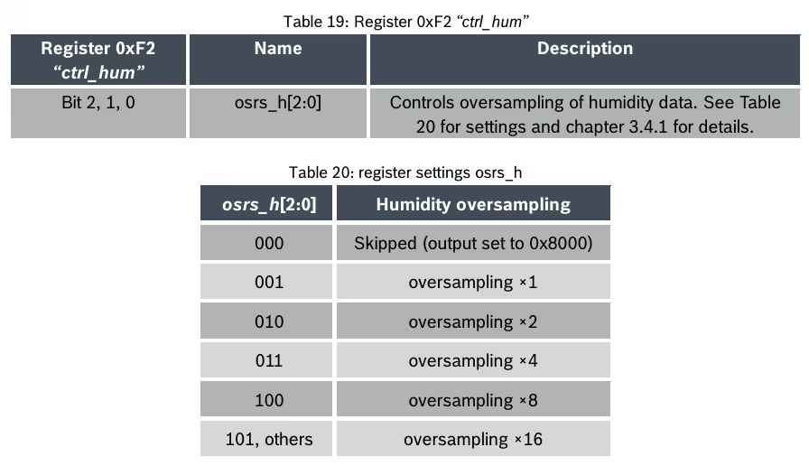
- Humidity measurement can be enabled or skipped.
- When enabled, you can choose from several oversampling options to reduce noise.
- The resolution of humidity is always 16 bits (fixed by the sensor).
- Oversampling improves stability of readings by averaging multiple measurements.
osrs_h Value | Oversampling | Measurement Result |
|---|---|---|
| 000 | Skipped | Humidity disabled |
| 001 | ×1 | 16-bit resolution |
| 010 | ×2 | Reduced noise |
| 011 | ×4 | Higher accuracy |
| 100 | ×8 | Very stable reading |
| 101 | ×16 | Maximum averaging |
Pressure Measurement (CTRL_MEAS Register – osrs_p[2:0])
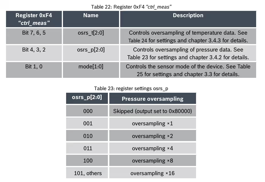
- Pressure measurement can also be enabled or skipped.
- Oversampling reduces noise and increases resolution.
- The resolution depends on the IIR filter setting:
- IIR Filter Enabled: Pressure resolution = 20 bits (maximum precision).
- IIR Filter Disabled: Pressure resolution = 16 + (osrs_p – 1) bits.
- Example: if
osrs_p = 3, resolution = 18 bits.
- Example: if
osrs_p Value | Oversampling | Resolution (Filter Off) | Resolution (Filter On) |
|---|---|---|---|
| 000 | Skipped | Disabled | Disabled |
| 001 | ×1 | 16-bit | 20-bit |
| 010 | ×2 | 17-bit | 20-bit |
| 011 | ×4 | 18-bit | 20-bit |
| 100 | ×8 | 19-bit | 20-bit |
| 101 | ×16 | 20-bit | 20-bit |
Temperature Measurement (CTRL_MEAS Register – osrs_t[2:0])
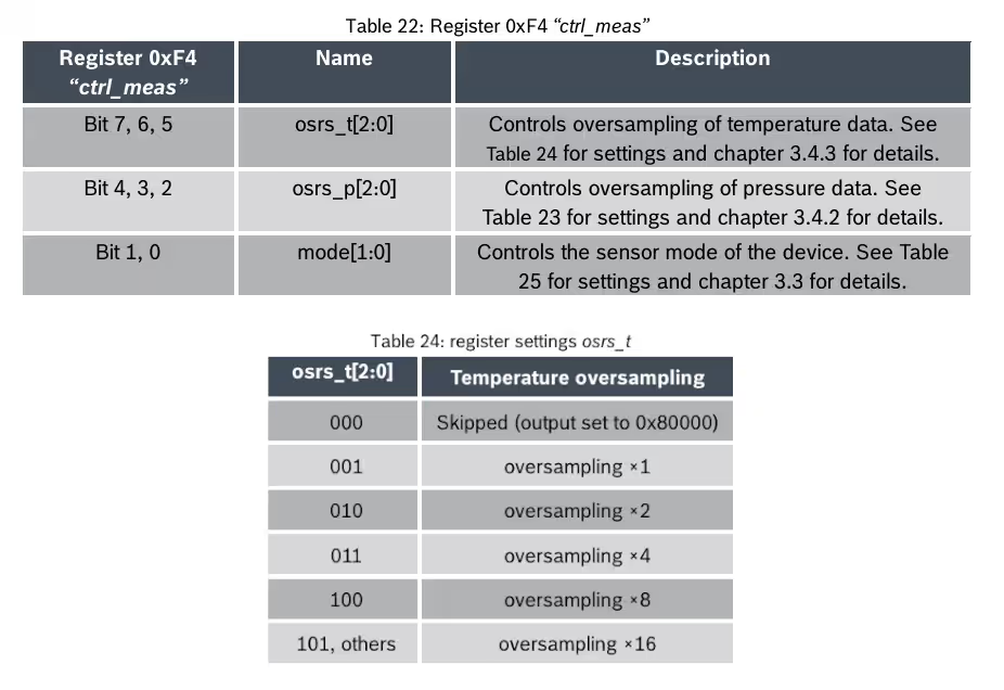
- Temperature measurement works in the same way as pressure.
- Oversampling options allow higher accuracy at the cost of time and power.
- Resolution is similar to pressure measurements, with up to 20-bit output when the filter is enabled.
osrs_t Value | Oversampling | Resolution (Filter Off) | Resolution (Filter On) |
|---|---|---|---|
| 000 | Skipped | Disabled | Disabled |
| 001 | ×1 | 16-bit | 20-bit |
| 010 | ×2 | 17-bit | 20-bit |
| 011 | ×4 | 18-bit | 20-bit |
| 100 | ×8 | 19-bit | 20-bit |
| 101 | ×16 | 20-bit | 20-bit |
Configuration Register (0xF5)
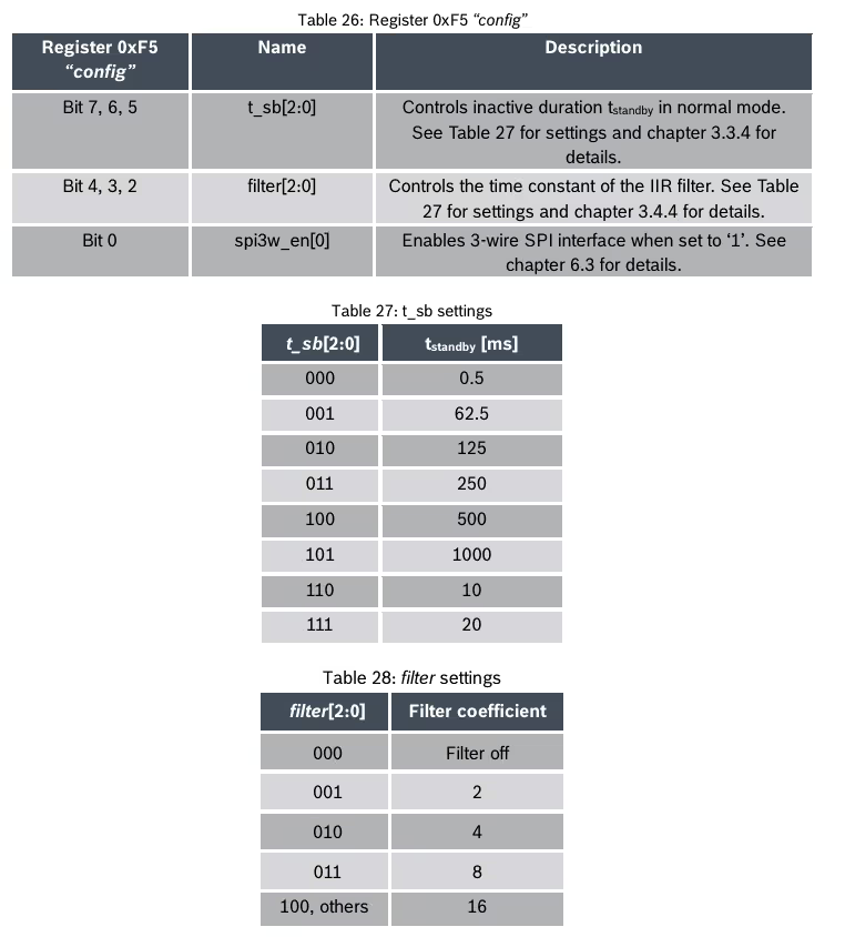
The CONFIG register controls the overall timing and filtering behavior of the sensor:
- Standby Time (bits 7,6,5): Defines the delay between measurements in Normal mode.
- IIR Filter Coefficients (bits 4,3,2): Used to smooth out short-term fluctuations in temperature or pressure readings.
- SPI Interface Mode (bit 0): Selects 3-wire or 4-wire SPI if using that interface.
| Bits | Function | Options |
|---|---|---|
| 7–5 | Standby Time (t_sb) | 000 = 0.5 ms, 001 = 62.5 ms, 010 = 125 ms, 011 = 250 ms, 100 = 500 ms, 101 = 1000 ms, 110 = 10 ms, 111 = 20 ms |
| 4–2 | Filter Coefficient | 000 = Off, 001 = 2, 010 = 4, 011 = 8, 100 = 16 |
| 0 | SPI Mode | 0 = 4-wire, 1 = 3-wire SPI |
Note: Writes to the CONFIG register while the sensor is in Normal mode may be ignored. Always configure it in Sleep mode for guaranteed updates.
Standby Time and Cycle Rate
The standby time combines with the measurement time to define the cycle time, which ultimately sets the output data rate (ODR).
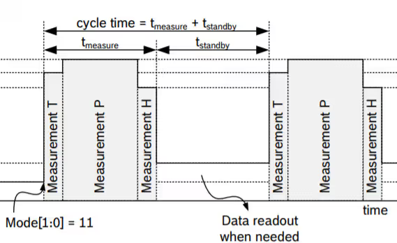
- Short standby time → faster data updates, higher power usage.
- Longer standby time → slower updates, lower power consumption.
This flexibility makes the BME280 suitable for both low-power IoT applications and high-precision monitoring systems.
Reading Raw Data from the BME280 Sensor
Once the BME280 is properly configured, the next step is to read the raw measurement data stored inside the sensor’s registers. The sensor continuously updates these registers with the latest temperature, pressure, and humidity values.
- Pressure and Temperature Data: Stored in registers from 0xF7 to 0xFC (a total of 6 bytes).
- 3 bytes each for pressure and temperature.
- Each forms a 20-bit raw value.
- Humidity Data: Stored in registers 0xFD and 0xFE (2 bytes).
- This gives a 16-bit raw value.
So, to get all readings, you need to perform a burst read of 8 bytes starting from 0xF7.
int32_t tRaw, pRaw, hRaw;

static int BMEReadRaw(void)
{
	uint8_t RawData[8];

	// Check the chip ID before reading
	HAL_I2C_Mem_Read(&hi2c1, BME280_ADDRESS, ID_REG, 1, &chipID, 1, 1000);

	if (chipID == 0x60)
	{
		// Read the Registers 0xF7 to 0xFE
		HAL_I2C_Mem_Read(&BME280_I2C, BME280_ADDRESS, PRESS_MSB_REG, 1, RawData, 8, HAL_MAX_DELAY);

		/* Calculate the Raw data for the parameters
		 * Here the Pressure and Temperature are in 20 bit format and humidity in 16 bit format
		 */
		pRaw = (RawData[0]<<12)|(RawData[1]<<4)|(RawData[2]>>4);
		tRaw = (RawData[3]<<12)|(RawData[4]<<4)|(RawData[5]>>4);
		hRaw = (RawData[6]<<8)|(RawData[7]);

		return 0;
	}

	else return 1;  //error NUM for debug
}Steps to Read Raw Data
- Verify the Chip ID by reading register
0xD0(should return0x60for BME280). - Perform an I2C/SPI burst read starting at register
0xF7. - Combine the bytes to form raw values:
- Pressure → 20-bit from 0xF7, 0xF8, 0xF9
- Temperature → 20-bit from 0xFA, 0xFB, 0xFC
- Humidity → 16-bit from 0xFD, 0xFE
- Store these raw values for compensation.
Note: The raw values cannot be used directly. They must be processed using calibration data and compensation formulas provided in the sensor’s datasheet. This step converts them into human-readable temperature (°C), pressure (Pa/hPa), and humidity (%RH).
Converting BME280 Raw Data to Real Values
The BME280 outputs raw ADC values for temperature, pressure, and humidity. These values cannot be used directly. Therefore, we must apply the calibration coefficients stored in the sensor’s internal memory to get meaningful readings.
Reading Calibration (Trimming) Parameters
The function TrimRead() reads calibration values (trimming parameters) from the BME280’s NVM (Non-Volatile Memory):
- Registers 0x88–0xA1 store temperature and pressure calibration values.
- Registers 0xE1–0xE7 store humidity calibration values.
static int TrimRead(void)
{
	uint8_t trimdata[32];

	// Read NVM from 0x88 to 0xA1 (25 bytes)
	if (HAL_I2C_Mem_Read(&BME280_I2C, BME280_ADDRESS, 0x88, 1, trimdata, 25, HAL_MAX_DELAY) != HAL_OK)
	{
			return 1;  //error NUM for debug
	}

	// Read NVM from 0xE1 to 0xE7 (7 bytes)
	if (HAL_I2C_Mem_Read(&BME280_I2C, BME280_ADDRESS, 0xE1, 1, trimdata + 25, 7, HAL_MAX_DELAY) != HAL_OK)
	{
		return 2;  //error NUM for debug
	}

	// Temperature coefficients
	dig_T1 = (uint16_t)(trimdata[1] << 8 | trimdata[0]);
	dig_T2 = (int16_t)(trimdata[3] << 8 | trimdata[2]);
	dig_T3 = (int16_t)(trimdata[5] << 8 | trimdata[4]);

	// Pressure coefficients
	dig_P1 = (uint16_t)(trimdata[7] << 8 | trimdata[6]);
	dig_P2 = (int16_t)(trimdata[9] << 8 | trimdata[8]);
	dig_P3 = (int16_t)(trimdata[11] << 8 | trimdata[10]);
	dig_P4 = (int16_t)(trimdata[13] << 8 | trimdata[12]);
	dig_P5 = (int16_t)(trimdata[15] << 8 | trimdata[14]);
	dig_P6 = (int16_t)(trimdata[17] << 8 | trimdata[16]);
	dig_P7 = (int16_t)(trimdata[19] << 8 | trimdata[18]);
	dig_P8 = (int16_t)(trimdata[21] << 8 | trimdata[20]);
	dig_P9 = (int16_t)(trimdata[23] << 8 | trimdata[22]);

	// Humidity coefficients
	dig_H1 = trimdata[24];
	dig_H2 = (int16_t)(trimdata[26] << 8 | trimdata[25]);
	dig_H3 = trimdata[27];
	dig_H4 = (int16_t)((trimdata[28] << 4) | (trimdata[29] & 0x0F));
	dig_H5 = (int16_t)((trimdata[30] << 4) | (trimdata[29] >> 4));
	dig_H6 = (int8_t)trimdata[31];

	return 0; //Success
}These are loaded into variables like dig_T1, dig_T2, dig_P1 … dig_P9, and dig_H1 … dig_H6.
These coefficients are unique to each sensor and must be used in every calculation.
Temperature Compensation
The function BME280_compensate_T_int32() uses dig_T1–T3 to correct the raw temperature.
- It outputs temperature in 0.01 °C (e.g., value
5123= 51.23 °C). - It also calculates a global variable
t_fine, which is required for pressure and humidity compensation.
static int32_t BME280_compensate_T_int32(int32_t adc_T)
{
	int32_t var1, var2, T;
	var1 = ((((adc_T>>3) - ((int32_t)dig_T1<<1))) * ((int32_t)dig_T2)) >> 11;
	var2 = (((((adc_T>>4) - ((int32_t)dig_T1)) * ((adc_T>>4) - ((int32_t)dig_T1)))>> 12) *((int32_t)dig_T3)) >> 14;
	t_fine = var1 + var2;
	T = (t_fine * 5 + 128) >> 8;
	return T;
}Pressure Compensation
The function BME280_compensate_P_int64() uses coefficients dig_P1–P9 and the t_fine variable.
static uint32_t BME280_compensate_P_int64(int32_t adc_P)
{
	int64_t var1, var2, p;
	var1 = ((int64_t)t_fine) - 128000;
	var2 = var1 * var1 * (int64_t)dig_P6;
	var2 = var2 + ((var1*(int64_t)dig_P5)<<17);
	var2 = var2 + (((int64_t)dig_P4)<<35);
	var1 = ((var1 * var1 * (int64_t)dig_P3)>>8) + ((var1 * (int64_t)dig_P2)<<12);
	var1 = (((((int64_t)1)<<47)+var1))*((int64_t)dig_P1)>>33;
	if (var1 == 0)
	{
		return 0; // avoid exception caused by division by zero
	}
	p = 1048576-adc_P;
	p = (((p<<31)-var2)*3125)/var1;
	var1 = (((int64_t)dig_P9) * (p>>13) * (p>>13)) >> 25;
	var2 = (((int64_t)dig_P8) * p) >> 19;
	p = ((p + var1 + var2) >> 8) + (((int64_t)dig_P7)<<4);
	return (uint32_t)p;
}The output is in Pa (Pascals), which can be divided by 100 to get hPa.
Humidity Compensation
The function bme280_compensate_H_int32() uses coefficients dig_H1–H6 along with t_fine.
static uint32_t bme280_compensate_H_int32(int32_t adc_H)
{
	int32_t v_x1_u32r;
	v_x1_u32r = (t_fine - ((int32_t)76800));
	v_x1_u32r = (((((adc_H << 14) - (((int32_t)dig_H4) << 20) - (((int32_t)dig_H5) *\
			v_x1_u32r)) + ((int32_t)16384)) >> 15) * (((((((v_x1_u32r *\
					((int32_t)dig_H6)) >> 10) * (((v_x1_u32r * ((int32_t)dig_H3)) >> 11) +\
							((int32_t)32768))) >> 10) + ((int32_t)2097152)) * ((int32_t)dig_H2) +\
					8192) >> 14));
	v_x1_u32r = (v_x1_u32r - (((((v_x1_u32r >> 15) * (v_x1_u32r >> 15)) >> 7) *\
			((int32_t)dig_H1)) >> 4));
	v_x1_u32r = (v_x1_u32r < 0 ? 0 : v_x1_u32r);
	v_x1_u32r = (v_x1_u32r > 419430400 ? 419430400 : v_x1_u32r);
	return (uint32_t)(v_x1_u32r>>12);
}- The output is in Q22.10 format, meaning the value must be divided by 1024 to get real %RH.
- Example: output
47445→ 46.33 %RH.
BME280_Measure() Function
The BME280_Measure() function works as a wrapper that performs all measurement steps. First, it calls BMEReadRaw() to get the latest raw temperature, pressure, and humidity values from the sensor. Then, it applies the compensation formulas using the stored calibration parameters. Finally, the function returns accurate temperature (°C), pressure (Pa/hPa), and humidity (%RH) values, which you can use directly in your application.
void BME280_Measure(float *temperature, float *pressure, float *humidity)
{
    if (BMEReadRaw() == 0)
    {
        if (tRaw == 0x800000) *temperature = 0; // temp disabled
        else
            *temperature = (BME280_compensate_T_int32(tRaw)) / 100.0f;

        if (pRaw == 0x800000) *pressure = 0; // pressure disabled
        else
        {
#if SUPPORT_64BIT
            *pressure = (BME280_compensate_P_int64(pRaw)) / 256.0f;
#elif SUPPORT_32BIT
            *pressure = (BME280_compensate_P_int32(pRaw));  // in Pa
#endif
        }

        if (hRaw == 0x8000) *humidity = 0; // humidity disabled
        else
            *humidity = (bme280_compensate_H_int32(hRaw)) / 1024.0f;
    }
    else
    {
        // if the device is detached
        *temperature = 0;
        *pressure    = 0;
        *humidity    = 0;
    }
}Configuring the BME280 Sensor for Measurement
The BME280_Config() function is responsible for setting up the measurement settings of the sensor before it starts capturing data. It writes the correct values to the control and configuration registers of the BME280 to define how the sensor should operate.
int BME280_Config (uint8_t osrs_t, uint8_t osrs_p, uint8_t osrs_h, uint8_t mode, uint8_t t_sb, uint8_t filter)
{
	// Read the Trimming parameters
	if (TrimRead() != 0)
	{
		return 1;
	}

	uint8_t datatowrite = 0;
	uint8_t datacheck = 0;

	// Reset the device
	datatowrite = 0xB6;  // reset sequence
	if (HAL_I2C_Mem_Write(&BME280_I2C, BME280_ADDRESS, RESET_REG, 1, &datatowrite, 1, 1000) != HAL_OK)
	{
		return 2;  //error NUM for debug
	}

	HAL_Delay (100);


	// write the humidity oversampling to 0xF2
	datatowrite = osrs_h;
	if (HAL_I2C_Mem_Write(&BME280_I2C, BME280_ADDRESS, CTRL_HUM_REG, 1, &datatowrite, 1, 1000) != HAL_OK)
	{
		return 3;  //error NUM for debug
	}
	HAL_Delay (100);
	HAL_I2C_Mem_Read(&BME280_I2C, BME280_ADDRESS, CTRL_HUM_REG, 1, &datacheck, 1, 1000);
	if (datacheck != datatowrite)
	{
		return 4;  //error NUM for debug
	}


	// write the standby time and IIR filter coeff to 0xF5
	datatowrite = (t_sb <<5) |(filter << 2);
	if (HAL_I2C_Mem_Write(&BME280_I2C, BME280_ADDRESS, CONFIG_REG, 1, &datatowrite, 1, 1000) != HAL_OK)
	{
		return 5;  //error NUM for debug
	}
	HAL_Delay (100);
	HAL_I2C_Mem_Read(&BME280_I2C, BME280_ADDRESS, CONFIG_REG, 1, &datacheck, 1, 1000);
	if (datacheck != datatowrite)
	{
		return 6;  //error NUM for debug
	}


	// write the pressure and temp oversampling along with mode to 0xF4
	datatowrite = (osrs_t <<5) |(osrs_p << 2) | mode;
	if (HAL_I2C_Mem_Write(&BME280_I2C, BME280_ADDRESS, CTRL_MEAS_REG, 1, &datatowrite, 1, 1000) != HAL_OK)
	{
		return 7;  //error NUM for debug
	}
	HAL_Delay (100);
	HAL_I2C_Mem_Read(&BME280_I2C, BME280_ADDRESS, CTRL_MEAS_REG, 1, &datacheck, 1, 1000);
	if (datacheck != datatowrite)
	{
		return 8;  //error NUM for debug
	}

	return 0;  //Success
}This function sets up the sensor’s oversampling, operating mode, standby time, and filter settings.
- Trimming Parameters:
First, the function reads the calibration (trimming) values stored in the sensor’s memory. These values never change and combine with raw measurements to give accurate results. - Device Reset:
After reading the trimming values, the sensor resets by writing 0xB6 to the Reset Register (0xE0). - Humidity Oversampling:
Next, the function sets the humidity oversampling by writing to the CTRL_HUM register (0xF2). - Filter and Standby Time:
Then, the function updates the CONFIG register (0xF5) to set the IIR filter coefficient and standby time.- The standby time starts at bit 5, so the value is shifted accordingly.
- The filter coefficient starts at bit 2, so this value is also shifted before writing.
- Pressure, Temperature, and Mode:
Finally, the function updates the CTRL_MEAS register (0xF4). This register controls:- Pressure oversampling (shifted by 2, starting at bit 2).
- Temperature oversampling (shifted by 5, starting at bit 5).
- Operating mode (controlled by the two lowest bits [1:0]).
After completing these steps, the BME280 is fully configured and ready to provide stable and accurate temperature, pressure, and humidity measurements.
BME280 Sensor STM32 HAL main function
In the main function we will simply configure the BME280 and the call the measure function to measure the data.
float Temperature, Pressure, Humidity;

int main(void)
{
  ....
  if (BME280_Config(OSRS_2, OSRS_16, OSRS_1, MODE_NORMAL, T_SB_0p5, IIR_16) != 0)
  {
	  Error_Handler();
  }

  while (1)
  {
	  BME280_Measure(&Temperature, &Pressure, &Humidity);
	  HAL_Delay (500);
  }
}First, we define the measurement variables as float.
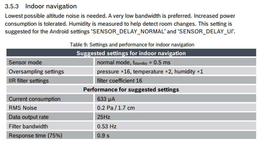
Inside the main() function, we call the BME280_Config() function to set up the sensor. In this example, the configuration is as follows:
- Temperature oversampling: ×2 (OSRS_2)
- Pressure oversampling: ×16 (OSRS_16)
- Humidity oversampling: ×1 (OSRS_1)
- Mode: Normal mode
- Standby time: 0.5 ms (T_SB_0p5)
- IIR filter coefficient: 16 (IIR_16)
These settings are taken directly from the example in the datasheet (see image below).
Inside the infinite while loop, we call BME280_Measure(). This function handles the raw data reading, applies the compensation formulas, and stores the final temperature, pressure, and humidity values in the variables we defined earlier.
Result of Interfacing BME280 with STM32
Below is the image showing the output values of all three parameters.
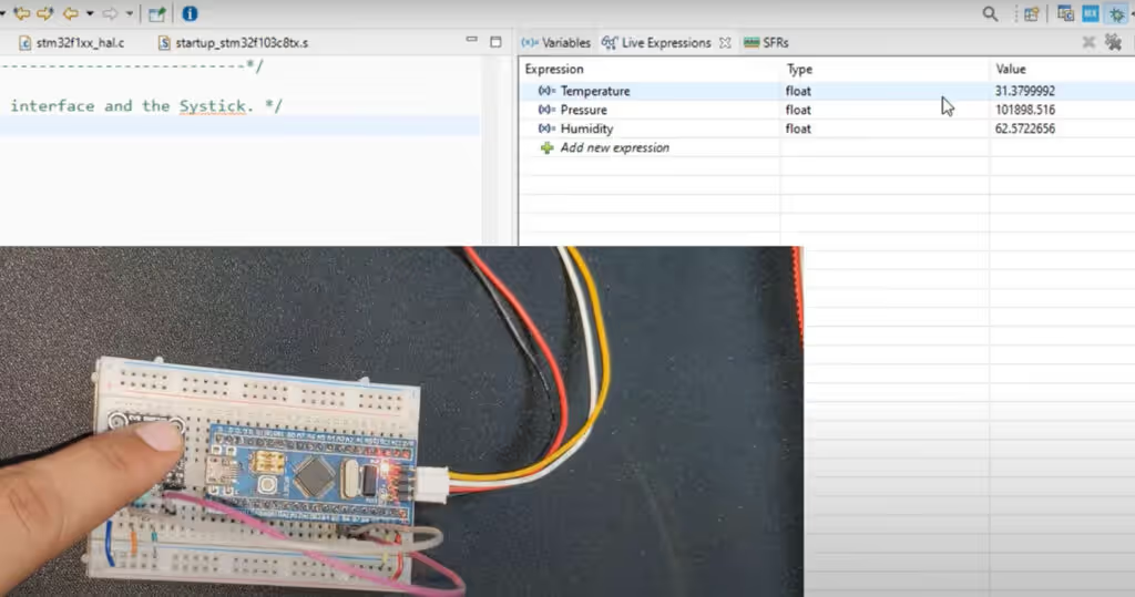
The debugger shows the Temperature, Humidity and Pressure values measured by the sensor.
In this project, we learned how to interface the BME280 sensor with an STM32 microcontroller using the I2C protocol. We started by understanding the sensor’s features, operating modes, and oversampling options. Then we configured the registers, read the raw data, and applied the compensation formulas using the trimming parameters stored in the device. Finally, we used the BME280_Measure() function inside the main() loop to obtain accurate temperature, pressure, and humidity values. With these steps, the BME280 is now ready to be used in STM32-based applications such as weather monitoring and IoT projects.
PROJECT DOWNLOAD
STM32 BME280 Sensor Project FAQs


Hello Sir can you address me how do i integrate turbidity and ph sensor with stm32Wl55j1 microcontroller.They both give analogue output,i tried them by accessing adc pin of stm32 but not getting answer.Kindly guide me regarding this.
Hello I am using the STM32L476RG with a BME280 but all values are zero, do you know how to fix it? In the debugger there are no warnings/errors. I am sure all the connections are right and I am using 4.7k resistor.
Hello would you be able to do this tutorial for a STM32 Nucleo L476RG with the BME280? I am having issues with it not working and I simply can not figure it out
Read the ID first to check if the connection is OK. If it doesn’t respond, try using 4.7K pull up resistors to the SCL and SDA Lines.
do you know why it doesn’t work on STM32L476?
There is no reason for it not to work on any MCU.
thanks for all that
actually i’ll be happier if you connect BME688 sensor to an stm32 board.
Hellow, thak you very much for your tutorials.
can anybody help me to perform SPI protocol.
Has anyone been successful with the 32-bit code? My pressure measurements are about 20% too low (displaying around 827 hPa when its actually around 1013hPs0. I get the same results with the code from the Bosch Github site. Used two different sensors, same results. Clues welcome.
I
m having the same problem. I tested the Adafruit lib and there is everything ok. Theres something wrong with the SPI interface.works 🙂 thank you!