Learn how to interface a PCF8574‑based I2C LCD1602 with ESP32 using ESP‑IDF. Complete wiring guide, address setup, init & string‑display code. The project is available to download at the end of the post.

This is the 3rd tutorial in the ESP32 series using the espressif-IDF and 1st in a mini series covering SPI peripheral of ESP32. We will cover the I2C peripheral in a 2 part series. In today’s tutorial I will only demonstrate how the ESP32 master will send the data to the slave device. In the text tutorial e will see how to read the data from the slave device.
For the demonstration purpose, I will use the LCD1602, which is connected via the PCF8574 I2C expander. The ESP32 will communicate with the PCF8574, which uses I2C communication, and this in turn will control the LCD.
VIDEO TUTORIAL
You can check the video to see the complete explanation and working of this project.
Introducing LCD1602 Character Display
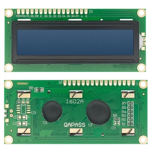
The LCD1602 is a 16×2 character display module based on the HD44780 controller. It can display 2 rows with 16 characters each and supports alphanumeric characters, symbols, and limited custom glyphs. Commonly used in embedded and microcontroller projects, it offers parallel and I2C interfaces (via PCF8574 adapter) for easy integration with platforms like Arduino, STM32, and ESP32.
Some of the important features of this display are:
- 16×2 alphanumeric character display
- Compatible with HD44780 controller
- I2C support via PCF8574 module
- Adjustable backlight and contrast
Introducing PCF8574
The PCF8574 is an 8-bit I/O expander IC from NXP that communicates via the I2C bus. It allows microcontrollers with limited GPIOs to control multiple digital I/O pins using just two I2C lines. It’s widely used to interface peripherals like LCDs, keypads, and LEDs in embedded systems.
Some of its important features are:
- 8-bit parallel I/O expansion via I2C
- Supports up to 8 devices on the same I2C bus
- Low power consumption and wide voltage range (2.5V–6V)
- Open-drain interrupt output for input change detection
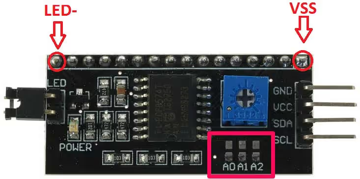
As you can see above PCF8574 has 4 input pins GND, VCC, SDA, SCL and 16 output pins. We will connect our LCD1602 to these 16 output pins.
SLAVE ADDRESS OF PCF8574
The General Address Pattern for this Device is 0100xxx in 7 bit Address system. The higher nibble of PCF8574 address is 0100 and this is fixed. But lower nibble (xxx) can be modified according to our convenience. The question you must be thinking is why we need to modify lower nibble?
Well you generally don’t but since we can connect up to 128 devices (7 bit Address system) on the same I2C line and let’s say we want to connect two different LCDs on the same I2C line, than we can’t use two PCF8574 with same addresses and we need to modify one of them.
Modify The Address
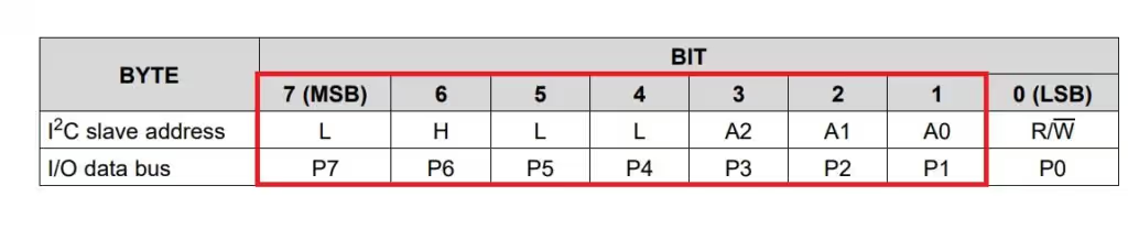
- The address of the PCF8574 is 0 1 0 0 A2 A1 A0. To change the address we are provided with A0, A1 and A2 pins.
- By default these three pins are HIGH so the address by default is 0100111 which is 0x27.
- To change the address of this device, you have to connect any/all of these three pins to ground, which is provided just above them (shown in the picture above).
- So let’s say you connected A0 to ground, new address will be 0100110 which is 0x26.
- In this manner, we can connect up to 8 LCDs to the same line.
- There is one more thing, the ESP32 takes 7 bit address for the I2C device. All the functions, which are included in the library of ESP32 will shift this address to the left by 1 bit, 0x27<<1, and the LSB here will be responsible for read(1)/ write(0) operation.
- If you plan to use the Registers instead of using the library functions, you need to give 8 bit address, 0 1 0 0 A2 A1 A0 R/W.
WIRING DIAGRAM
As shown in the first picture, the first pin of the device is Vss which is pin 1 of LCD. So all you have to do is connect first pins of the LCD to Vss above and rest will connect accordingly. Starting with Vss as first pin, connection is as follows:-
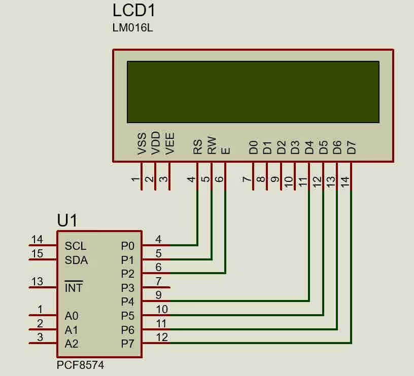
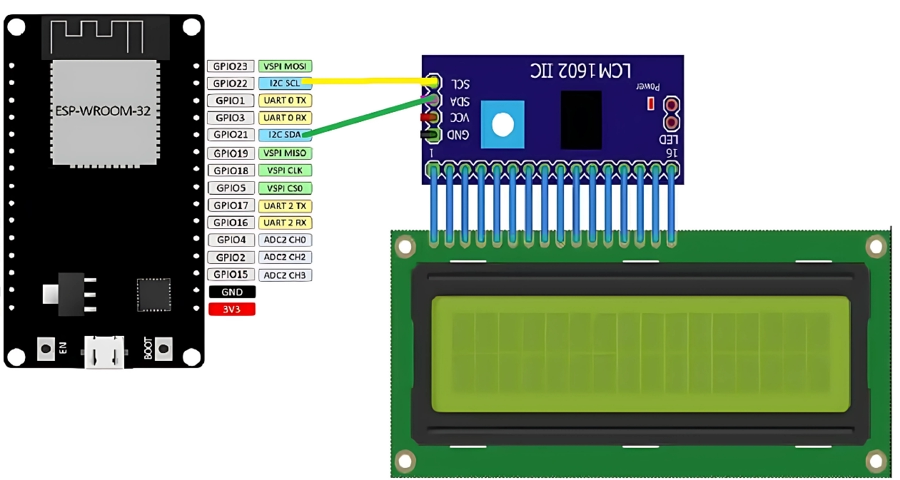
The LCD1602 have 8 Data Pins (D0 to D7). Although the LCD can be used in the 8 bit mode, where it utilises all 8 data pins, or in the 4 bit mode, where it only untilses the 4 pins (D4 to D7).
As shown in the picture above, the PCF8574 is only utilising the 4 Data pins from the LCD, so we must use the LCD in the 4 bit mode.
THE CODE
We will divide this section into 2 parts. In the first part, we will talk about the ESP32 and it’s I2C functions that we are going to use, and in the second part we will see the LCD related functions.
ESP32 I2C Functions
static esp_err_t i2c_master_init(void)
{
    i2c_config_t conf = {
        .mode = I2C_MODE_MASTER,
        .sda_io_num = GPIO_NUM_21,
        .scl_io_num = GPIO_NUM_22,
        .sda_pullup_en = GPIO_PULLUP_ENABLE,
        .scl_pullup_en = GPIO_PULLUP_ENABLE,
        .master.clk_speed = 100000,
    };

    i2c_param_config(I2C_NUM_0, &conf);

    return i2c_driver_install(I2C_NUM_0, conf.mode, 0, 0, 0);
}The i2c_master_init function will be used to initialise the I2C in the master mode. Here we will first configure the I2C parameters, which are as follows
- mode sets the mode for the I2C. It can be either master/slave. Since we want the ESP32 to be a master, we will set the I2C_MODE_MASTER
- sda_io_num sets the GPIO for the SDA(Data Pin). As shown in the connection diagram, the SDA is the GPIO_NUM_21
- scl_io_num will set the GPIO for the SCL (Clock Pin)> It is defined as GPIO_NUM_22
- pullup_en basically configures if you want to enable the internal pullups for the SDA and SCL Pins. Since we are not using any external pullup resistors, we should enable the internal pullups.
- master.clk_speed configures the speed (in Hz) for the master. Most of the devices work at 100Khz, or 400Khz. The PCF can work with 100Khz, so I have it to 100000.
i2c_param_config will configure the parameters we just set. I2C_NUM_0 is the I2C instance we are using. If your board have more than 1 I2C, then you should define the instance as per the pins you are using.
After configuring the parameters, i2c_driver_install will install the driver. The parameters are
- i2c_port_t, the I2C instance, which is 0 in our case.
- i2c_mode_t mode, the I2C mode, which is master in this case.
- slv_rx_buf_len and slv_tx_buf_len, The size of the RX and TX buffers. The buffers are only needed if the ESP32 is being used in the slave mode. Since we are using it as a master, we will keep these buffers as 0.
- intr_alloc_flags is to set the interrupt flag for the I2C. We will keep it as 0 too, since we are not using any interrupts.
Next let’s see a function to write the data to the Device.
i2c_master_write_to_device(i2c_port_t i2c_num, uint8_t device_address,
                                     const uint8_t* write_buffer, size_t write_size,
TickType_t ticks_to_wait)As the name suggests, the i2c_master_write_to_device is used to write the data to the device. It’s parameters are :
- i2c_num, The I2C instance that you are using.
- device_address, the 7 bit address of the slave device.
- write_buffer, the buffer that you want to send to the slave device. This buffer can contain the registers of the device, that you want to write he data to, and the data itself. Or it can only contain the data. It basically depends the type of the slave device.
- write_size, the size of the write buffer, in bytes of course.
- ticks_to_wait, The timeout for the write function to complete, in milliseconds.
This function returns 0, if the write was successful, or any other number in case of any error.
LCD Related Functions
In order to initialise the LCD, we need to send some set of commands. The i2c-lcd library contains these commands and the functions which send these commands and data to the LCD.
In order to send the command or data to the LCD, we need to follow some set of steps:
- Set/Reset the data pins (D0 – D7) with respect to what data we want to write
- Send a strobe signal, which is basically setting the ENABLE pin, and then Resetting it.
To differentiate between data and command, the LCD have a pin (RS). This pin must be Reset while sending the command, and it must be Set while sending the data.
Below is the function to send the command.
void lcd_send_cmd (char cmd)
{
	esp_err_t err;
	char data_u, data_l;
	uint8_t data_t[4];
	data_u = (cmd&0xf0);
	data_l = ((cmd<<4)&0xf0);
	data_t[0] = data_u|0x0C;  //en=1, rs=0
	data_t[1] = data_u|0x08;  //en=0, rs=0
	data_t[2] = data_l|0x0C;  //en=1, rs=0
	data_t[3] = data_l|0x08;  //en=0, rs=0

	err= i2c_master_write_to_device (I2C_MASTER_NUM, SLAVE_ADDRESS_LCD, data_t, 4, 1000);
	if (err != 0) ESP_LOGI(TAG, "Error no. %d in command", err);
}As I have already mentioned, the PCF8574 is connected to 4 data pins (D4 – D7), so we will be using the LCD in 4 bit mode. This means we only have 4 data pins available to write a 8 bit data.
We do this by sending the data into 2 halves (4 bit each).
- Here first we will separate the upper 4 bits (stored in data_u) and lower 4 bits (data_l) from the command.
- We have to tell the LCD that it’s a command, and we do that by pulling the RS pin LOW.
- We also have to this each half twice, once when the EN (enable) pin is HIGH, and when it’s LOW. This acts like the strobe I just mentioned above.
- Once the data is stored in the buffer (data_t), we will write this to the device using the function
i2c_master_write_to_device. - If there is some error while sending this to the device, the Error will Log it into the console.
The Data is sent in the similar manner, except that the RS Pin must be HIGH to indicate that this is the data (not the command) we are sending. You can check the library for the function.
Initialise the LCD
Below is the code to initialise the LCD in 4 bit mode.
void lcd_init (void)
{
	// 4 bit initialisation
	usleep(50000);  // wait for >40ms
	lcd_send_cmd (0x30);
	usleep(4500);  // wait for >4.1ms
	lcd_send_cmd (0x30);
	usleep(200);  // wait for >100us
	lcd_send_cmd (0x30);
	usleep(200);
	lcd_send_cmd (0x20);  // 4bit mode
	usleep(200);

  // dislay initialisation
	lcd_send_cmd (0x28); // Function set --> DL=0 (4 bit mode), N = 1 (2 line display) F = 0 (5x8 characters)
	usleep(1000);
	lcd_send_cmd (0x08); //Display on/off control --> D=0,C=0, B=0  ---> display off
	usleep(1000);
	lcd_send_cmd (0x01);  // clear display
	usleep(1000);
	usleep(1000);
	lcd_send_cmd (0x06); //Entry mode set --> I/D = 1 (increment cursor) & S = 0 (no shift)
	usleep(1000);
	lcd_send_cmd (0x0C); //Display on/off control --> D = 1, C and B = 0. (Cursor and blink, last two bits)
	usleep(2000);
}As I mentioned, we send some set of commands to initialise the LCD, and you can see them in the code above. The usleep function put the MCU in sleep and it takes the argument in microseconds.
The initialisation pattern is shown in the picture below from the datasheet.
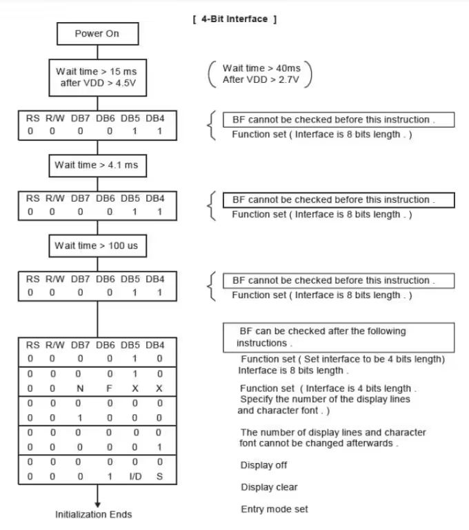
The first few commands should be similar to how they have provided in the datasheet, but after setting the 4 bit mode (after display initialisation in the code), you can modify the registers as per your need.
For example if you want to set the blinking cursor, or cursor moving direction, or display shifts etc. You need to see the registers mentioned in the datasheet, and set the values accordingly.
I have kept it simple in the library I am using here.
Other LCD functions
Other than initialisation, we do have few more functions to have better control over the LCD
void lcd_put_cur(int row, int col)
{
    switch (row)
    {
        case 0:
            col |= 0x80;
            break;
        case 1:
            col |= 0xC0;
            break;
    }

    lcd_send_cmd (col);
}lcd_put_cur is used to put the cursor at the respective location on the LCD. As we already know, the LCD1602 have 2 Rows (0-1) and 16 Columns (0-15).
The DDRAM Address for the LCD1602 starts from the 0x80. So If we tell LCD to put the cursor at 0x80, it will basically put it in the beginning of the Top Row. Then the next Position will be 0x81, 0x82 and so on, upto 0x8F.
The beginning of the bottom row starts from 0xC0, and goes all the way upto 0xCF.
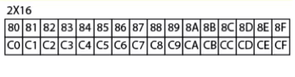
For example, If i want to put the cursor at the position (0,5), then the code will add 0x80 and 0x05, making it 0x85 and send this command to the LCD.
After we put the cursor at certain location, we can send the data to it, which will be displayed on the LCD.
Sending data
void lcd_send_string (char *str)
{
	while (*str) lcd_send_data (*str++);
}The lcd_send_data function is generally used to send the data to the LCD. This function prints a single character and the argument of this function should be the ascii character that you want to print on the display, for eg- lcd_send_data (‘A’) or lcd_send_data (0x41) or lcd_send_data (65), all will print the character A on the LCD.
lcd_send_string can be used to send a character string, or a buffer (containing characters) to the display.
You can only print characters on the LCD. So if you want to print numbers, you need to change them to equivalent ascii characters, and then send them to the display. It is shown as we progress in this tutorial.
Clearing LCD
LCD 1602 have a command to clear the entire screen.
void lcd_clear (void)
{
	lcd_send_cmd (0x01);
	usleep(5000);
}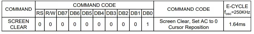
0x01 can be used to clear the entire screen and set the cursor to the beginning, i.e at the 0x80 location. The command needs some time to execute, and therefore we have to provide some delay.
The main function
void app_main(void)
{
    ESP_ERROR_CHECK(i2c_master_init());
    ESP_LOGI(TAG, "I2C initialized successfully");

    lcd_init();
    lcd_clear();

    lcd_put_cur(0, 0);
    lcd_send_string("Hello World!");

    lcd_put_cur(1, 0);
    lcd_send_string("from ESP32");
}- In the main function, first of all we will initialise the I2C driver. Remember that this must be done before we call any LCD related functions, since the LCD functions uses the I2C.
- Then we will initialse the LCD.
- We will put the cursor at 0th Row and 0th Column and print “Hello World!” string at this position.
- Similarly, we will print “from ESP32” in the bottom row.
The output of the above code is shown below.

Now suppose we want to display a number on the LCD. As I mentioned, we need to change it to the characters and then display it. The code for the same is shown below
char buffer[10];
float num = 1234;

void app_main(void)
{
    ESP_ERROR_CHECK(i2c_master_init());
    ESP_LOGI(TAG, "I2C initialized successfully");

    lcd_init();
    lcd_clear();

    sprintf(buffer, "val=%d", num);
    lcd_put_cur(0, 0);
    lcd_send_string(buffer);
}- Here We will first define a character buffer to store the number, when it will converted to character form.
- We can use sprintf to do the conversion from number to string format.
- Once the string has been stored in the buffer, we can print it at the desired location.
The output for the above code is shown below
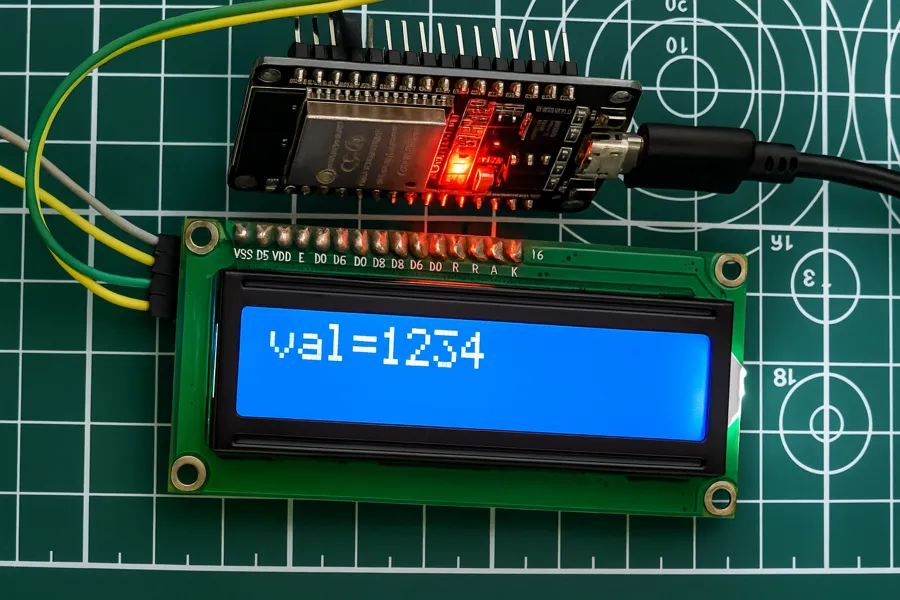
Similarly you can print float numbers by changing the format identifier (to %f) in the sprintf function.
PROJECT DOWNLOAD


how do you fix the problem with idf ver. 5.3.1 and the new i2c ?
Thank you for posting this tutorial. It very useful and working fine. Able to display message on LCD.
Hi, the links are broken
Thanks for informing. They are fixed now.
I’m trying to use Espressif-IDE to make LCD working with I2C but when i use the code from the video or from this link nothing displays at all on my LCD. I dont know if its the lcd address or if its something else. Can you help me?
Thank you for this component, I have launched and it works 🙂 how to get the LCD backlight control?
What is the I2C_MASTER_NUM? Can someone help me?
It is the I2C instance. For example, If the MCU has 2 I2Cs, then you have to define which one you are using. I2C_NUM_0 or I2C_NUM_1.
I want to donate,but paypal is not allowing me,because i have rupye card.please provide alternate like paytm,gpay
arun2112@pingpay
Thank you for this wonderful write up. This worked for me. However, I am trying to get a 4×4 matrix keypad hooked up to PCF8574 and read from it. I am coding on esp-idf. I am wondering if the “i2c_master_read_from_device” function made available in esp-idf 4.4 should be the one I should use. But since the matrix keypad has no power on its own (no vcc or gnd pins), I am given to understand that I have to first write to the PCF8574 register (GPIO pins) and then immediately read from it every time, and find out which key has been depressed based on which pins go low. I do not know if this understanding is correct as I could not find any examples. All examples I come across are only on arduino and using Wire.h which are not useful for me. The reason I am only interested to use esp-idf is because I want to use the interrupt capability in PCF8574 as a keypad interrupt in due course. Do you have any examples to share for esp-idf 4.4 ? Any help would be appreciated. Thanks much
very interesting suggestion. As far as I know you can not set the individual pins as output or input using the registers in PCF8574.
We require 4 pins as output, which we pull high, and then 4 pins as input, where we check the voltage.
As you mentioned there are some Arduino examples, so if you can link one or two of them, I can give you a better suggestion for this.
I do not get messages on LCD as expected. I only get some characters not the message HelloWorld from ESP32 on the display. Please help
Those characters may be the ascii equivalent of what you are trying to print. It happened to me as well when I daisy chained two PCF8574 expanders, with the LCD on the end of the chain. When I tried with only one PCF8574 expander, the characters printed correctly. To fix my problem, I changed the .master.clk_speed = 400000. i.e. 400KHz as fast–mode I2C clock. And then the characters appeared correctly.