
Home ▸ STM32 Tutorials ▸
Updated On: September 14, 2025
STM32 as I2C SLAVE || PART 1
This is a new series and it will cover how to write the program to make the STM32 MCU as an I2C slave. We will cover the different aspects of a slave device in different parts of this series.
Today for the first tutorial in this series we will see how to do the basic setup and start receiving the data under certain conditions.
Let’s start with the cubeMX setup
VIDEO TUTORIAL
You can check the video to see the complete explanation and working of this project.
CubeMX Setup
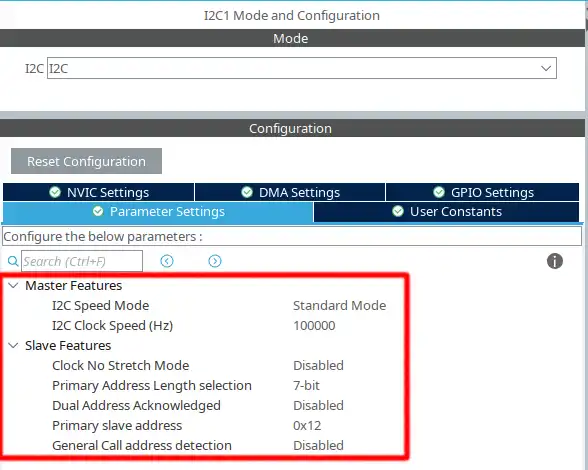
Above shown is the configuration for the I2C1
- The mode is set as standard mode with the clock speed of 100000 Hz
- The
Clock No Stretch Modeis disabled, that means the Clock stretching is enabled. - The Primary slave address length is 7 bit and the address for the device is set to 0x12 (7 bit)
- The STM32 I2C is capable of acting as 2 different slave devices with 2 different addresses, but it is disabled, and there will be only 1 slave.
- We will cover more about Clock stretching and General call address detection in the upcoming tutorials.
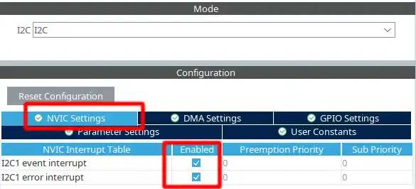
We also need to enable the Event Interrupt and Error Interrupt in the NVIC Tab
The pinout is shown below
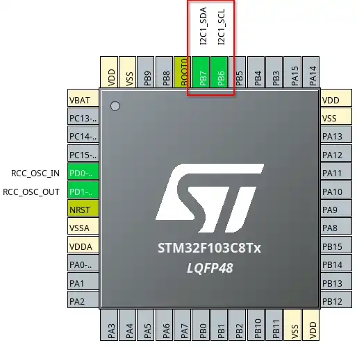
The pin PB6 is the SCL (Clock) pin and must be connectde to the SCL pin of the master. The pin PB7 is the SDA (Data) pin and must be connected to the SDA of the master. If you are connecting 2 similar MCUs, you can connect the same pins together. For eg- PB6 -> PB6 and PB7 -> PB7.
Some Insight into the CODE
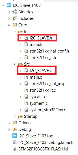
I have created separate file to write the source code for the I2C Slave.
The i2c_slave.c is in the src folder and the i2c_slave.h is in the inc folder. The image is shown below.
First of all we will put the I2C in the Listen mode. This is done in the main file. The Listen mode is enabled in the interrupt mode.
HAL_I2C_EnableListen_IT(&hi2c1);I2C_Slave.c
Once the master tries to communicate with the slave, an interrupt will trigger and the listen complete callback is called.
extern void HAL_I2C_ListenCpltCallback (I2C_HandleTypeDef *hi2c)
{
	HAL_I2C_EnableListen_IT(hi2c);
}Inside the callback we will enable the listen mode again, so that the device is always looking for the command/data from the master.
If the device address sent by the master matches with the device address of the STM32 I2C, an interrupt will again triiger and the address callback is called.
extern void HAL_I2C_AddrCallback(I2C_HandleTypeDef *hi2c, uint8_t TransferDirection, uint16_t AddrMatchCode)
{
	if(TransferDirection == I2C_DIRECTION_TRANSMIT)  // if the master wants to transmit the data
	{
		HAL_I2C_Slave_Sequential_Receive_IT(hi2c, RxData, 6, I2C_FIRST_AND_LAST_FRAME);
	}
	else  // master requesting the data is not supported yet
	{
		Error_Handler();
	}
}Here the important parameter is the TransferDirection. It indicates whether the master wants to write the data or is it requesting the data from the slave.
- If the TransferDirection is I2C_DIRECTION_TRANSMIT, that means the master wants to transmit the data.
- In that case, the slave must receive the data and store it in the buffer.
We will use the sequential functions for the slave to receive and transmit data throughout these tutorials. The sequential functions support the restart condition sent by the master, so these functions are perfect to wite the slave code.
Here we use the function Sequential_Receive_IT to receive the data in the interrupt mode. The Data is stored in the RxData buffer and the device can receive 6 bytes at once.
The last parameter of the seuential receive function is the Transfer Option (XferOptions). This parameter basically decides how the data will be received by the slave. We have a lot of options available for this parameter, and each option decides whether the slave will send a NACK to the master or not.
Here I am using the option I2C_FIRST_AND_LAST_FRAME. This means that the slave is receiving the first frame and the last frame in this function itself. Basically after receiving the 6 bytes, the slave will send a NACK response to the master irrespective of whether the master wants to send more data or not.
The slave is always looking for 6 bytes of data. So if the master sends less than 6 bytes, a stop condition will be detected by the slave and the AF (ACK FLAG) error will be set in the slave. We will see errors in some other tutorial, so for now we will just ignore the AF error.
If the master sends 6 bytes of data, the slave will happily receive it and the receive complete callback will be called.
void HAL_I2C_SlaveRxCpltCallback(I2C_HandleTypeDef *hi2c)
{
	count++;
}We have nothing special to do in the receive complete callback function, so we will just increment the count variable. This will indicate the number of times this function has been called.
void HAL_I2C_ErrorCallback(I2C_HandleTypeDef *hi2c)
{
	HAL_I2C_EnableListen_IT(hi2c);
}If there iss ssome error during reception, the error callback is called. As I mentioned we will not be handling error in today’s tutorial, so here we will just enable the listen mode again.
The Master code
You can use another STM32 as the master.
  /* USER CODE BEGIN 2 */

  uint16_t slaveADDR = 0x12<<1;
  uint8_t TxData[6] = {0x1, 0x2, 0x3, 0x4, 0x5, 0x6};
  while (1)
  {
	  HAL_I2C_Master_Transmit(&hi2c1, slaveADDR, TxData, 6, 1000);
	  HAL_Delay (1000);
}We can program the master to transmit data every 1 seond.
- First set the device address. It has to be a 8 bit address, so we need to shift the 0x12 (7bit Address) to the left by 1.
HAL_I2C_Master_Transmitcontinuously transmits the 6 bytes of data (TxData) to the slave device.
RESULT
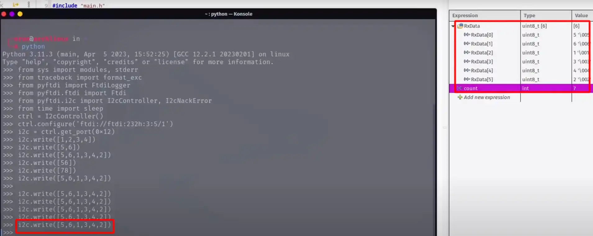
As you can see in the image above, The data sent by the master and the data received by the slave is same. Alsso the count variable increases whenever the slave receives 6 bytes data.
In case the data sent by the master is less than 6 bytes, the slave will trigger the AF error, which we will handle in future tutorials. But for now the slave will even store that data in the buffer and look for the new data.
STM32 I2C Slave Tutorial Series

STM32 as I2C SLAVE || PART 3

STM32 as I2C SLAVE || PART 4

STM32 as I2C SLAVE || PART 5

STM32 as I2C SLAVE || PART 6

STM32 as I2C SLAVE || PART 7


>>> from pyftdi import FtdiLogger
Traceback (most recent call last):
File “”, line 1, in
ModuleNotFoundError: No module named ‘pyftdi’
Due to the inability to view the advertisement, the source code cannot be downloaded. You can send the source code to [email protected] Is it an email?