
Home ▸ STM32 Tutorials ▸
Updated On: March 23, 2026
How to create and use the W25Q External Loader
This is the 8th tutorial in the W25Q Flash series, and today we will see how to create and use the External Loader for the W25Q flash memory with the QuadSPI peripheral. In this tutorial we will first create an external loader for the combination of the STM32L496 MCU and the W25Q32JVSSIQ nor flash memory from winbond, and later we will program the external flash using the loader. We will also see how to map data (images or something else) to the external flash.
VIDEO TUTORIAL
You can check the video to see the complete explanation and working of this project.
Prerequisite
This is going to be a continuation from the previous tutorial, so you must go through W25Q PART 7 before continuation with this tutorial. I will skip the basic connection, read, write in the quadSPI mode, as it has already been covered in the previous tutorial.
ST has a repository for the external loader, where they have specified the process to build it for a specific MCU. We will follow the same process in this tutorial. I would advise you to download the entire folder linked above.
Create the Loader
We need to first copy certain files from the ST’s folder into our project. Open the ST’s folder -> Loader_files. If you have H7 device, open the respective folder, otherwise open the Other devices folder.

Now copy the ***.c files in the src directory of the project, ***.h file in the inc directory and the linker file in the main project folder. The final project structure is shown below.
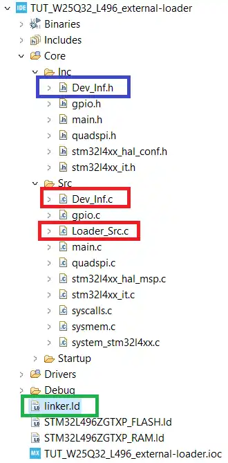
You can set the Loader name in the Dev_inf.c file as shown below. Also make sure to cross check the QSPI start Address (0x90000000 in this case) with the reference manual of your MCU.
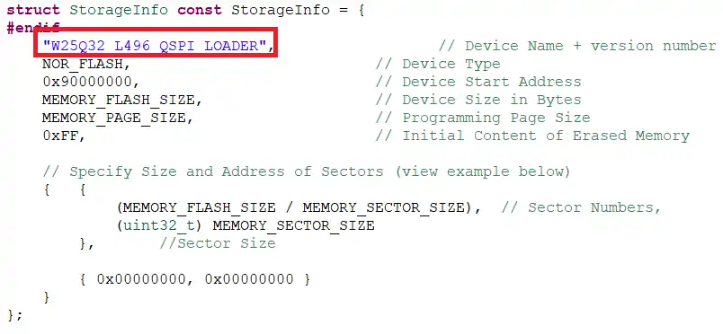
Other details like MEMORY_FLASH_SIZE, PAGE_SIZE, SECTOR_SIZE are fetched from the QuadSPI.h file we defied in the previous tutorial.
Now we need to set the linker file for the project.
Go to Project Properties -> C/C++ Build -> Settings -> MCU GCC Linker -> General. Here change the Linker Script to the Linker file we copied.
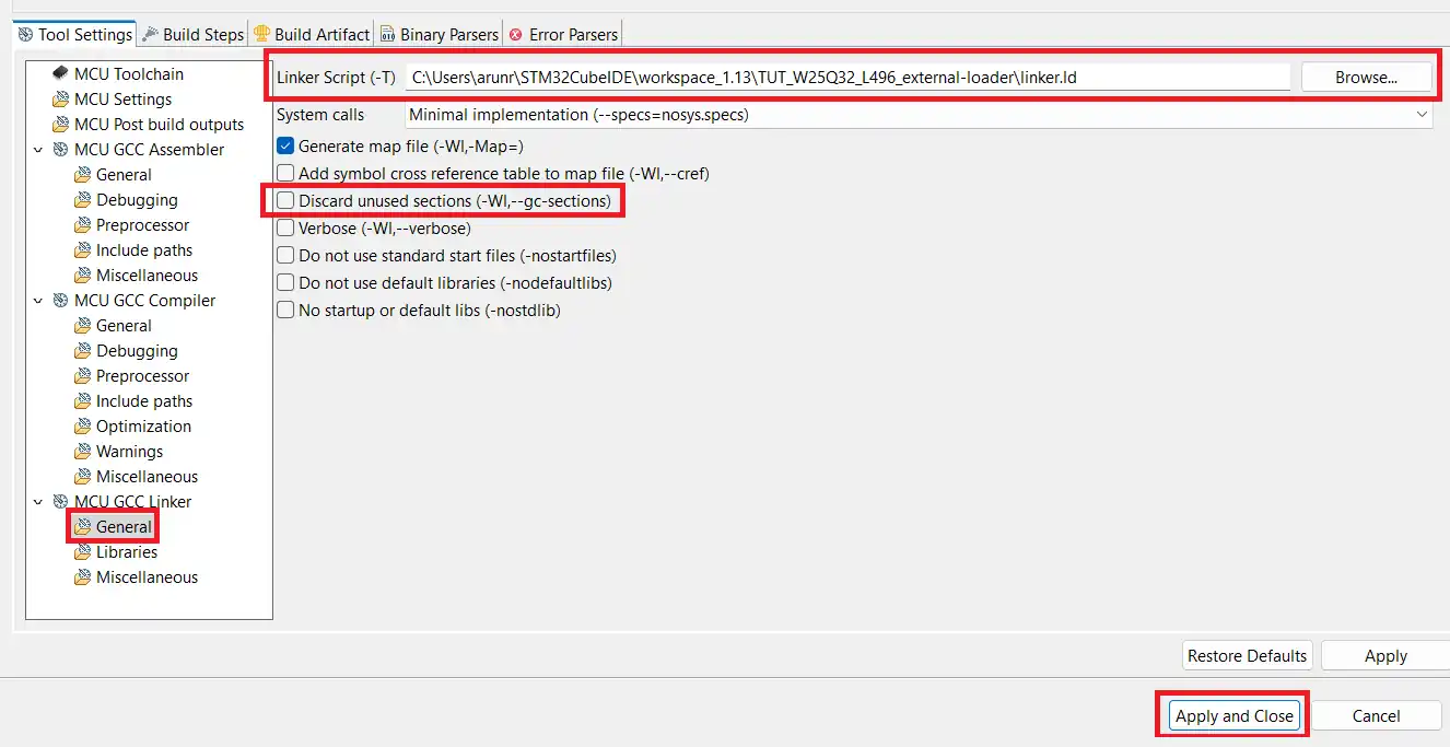
As shown above i have changed the Linker Script to the linker.ld file. Also make sure to uncheck the Discard unused sections. After making the changes, click on Apply and Close.
We also need to copy the post build command to the Build Steps tab as shown below.
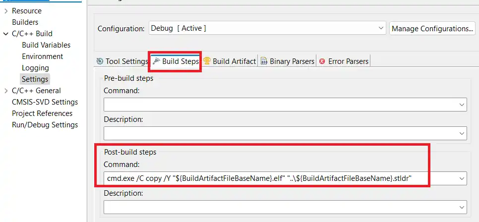
The command is cmd.exe /C copy /Y “${BuildArtifactFileBaseName}.elf” “..\${BuildArtifactFileBaseName}.stldr”. It will copy the stldr file (loader) to the main project folder.
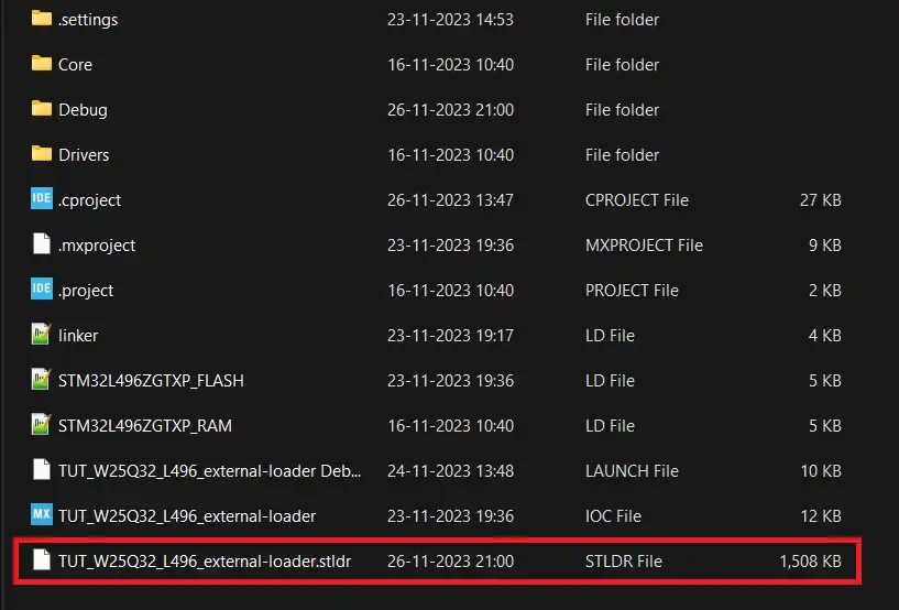
Now build the code, and you should see the Loader file (***.stldr) in the main project folder itself. This is shown below.
Usage with CubeProgrammer
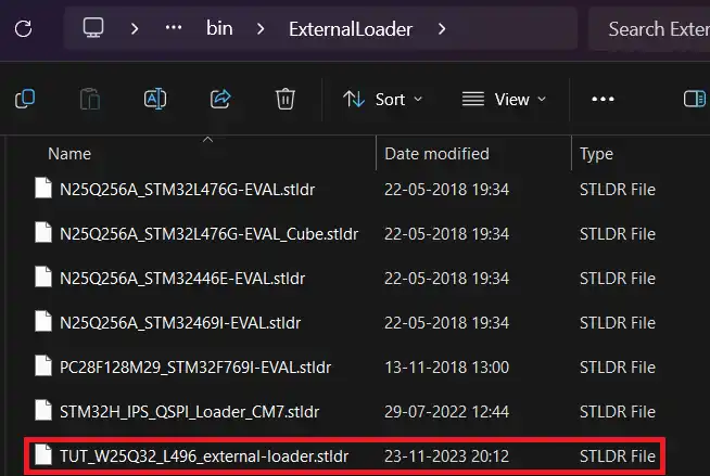
We need to first copy the Loader to the cubeprogrammer directory. Copy the ***.stldr file to the C:\Program Files\STMicroelectronics\STM32Cube\STM32CubeProgrammer\bin\ExternalLoader
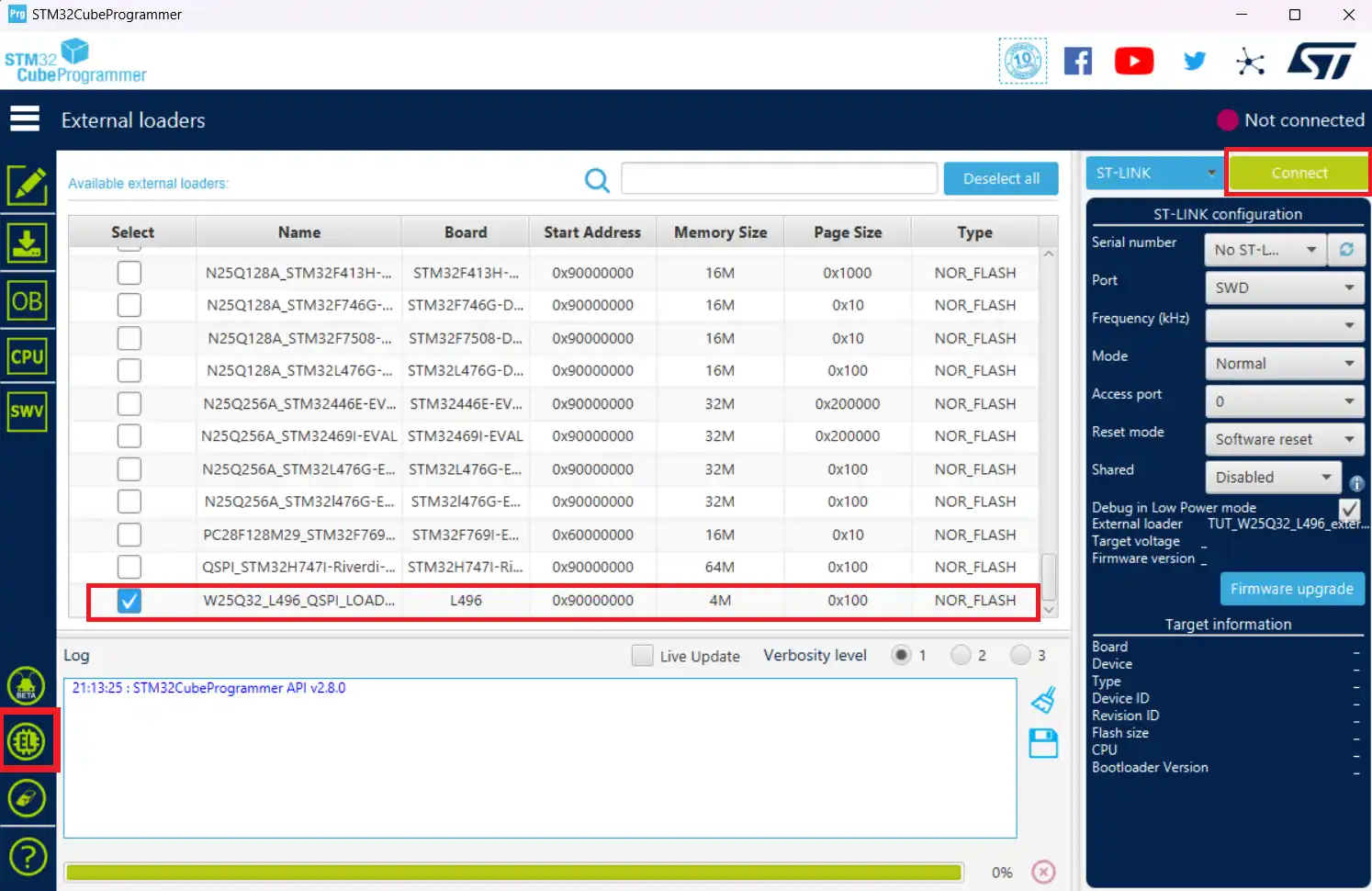
Now open the cube programmer. Go to the EL (External Loader) section and select the loader. Then connect the board to the programmer.
We can program the bin file directly to the flash memory. To test it, ST’s folder has a testbinary1M.bin file. We will load this file to the W25Q flash.
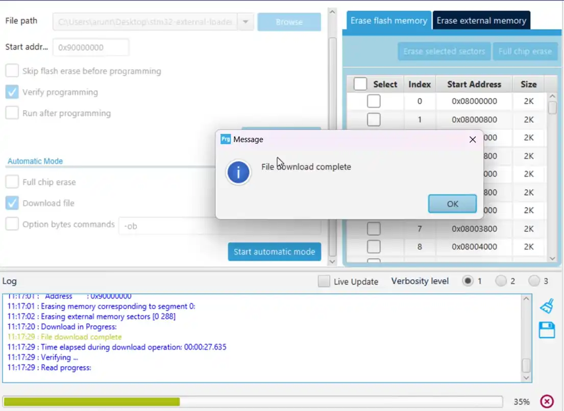
Go to the Download section, Browse the testbinary1M.bin, enter the QSPI Start Address, and start programming.
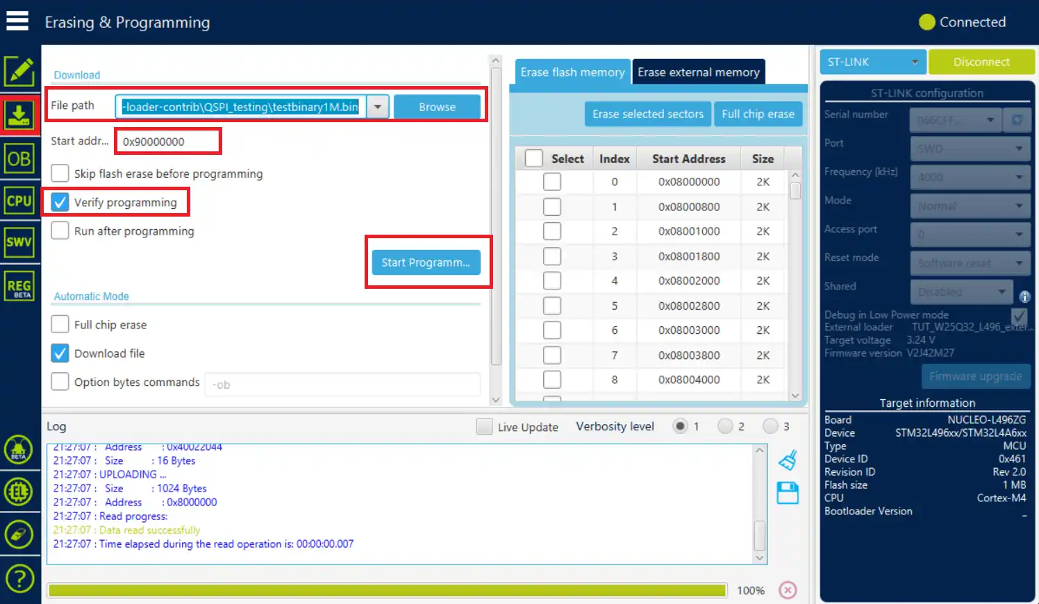
You should see 2 notifications, the first one will pop up once the file has been downloaded to the memory, and another when the downloaded file has been verified.
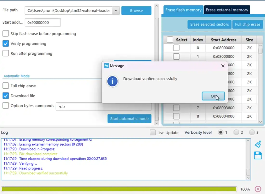
The file has been downloaded and verified means that the external loader is working fine. You can see the content of the external flash in the memory tab.
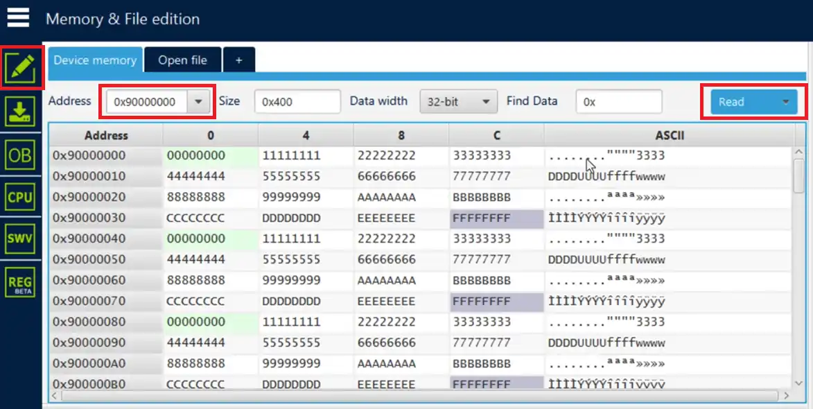
Enter the QSPI address and click on Read button to read the external flash memory. The content you see above was written by the testbinary1M.bin file.
Usage with cubeIDE
We can use the external loader to debug the external memory in cubeIDE.
Basically we will reallocate a data buffer to the external memory. This data buffer can be an image file, or an audio or video file, as it takes a lot of space in the internal flash memory. We need to initialize the QSPI memory in the memory mapped mode, and the external loader is needed to reallocate the buffer.
The main file
Below is the code needed to implement in the main file.
const __attribute__((section(".extflash"))) uint8_t writebuf[] = "Hello world from QSPI";

uint8_t Readbuf[100];Here I am allocating the writebuf to a specific section (extflash). We will define this section in the flash script file.
  /* USER CODE BEGIN 2 */

  if (CSP_QUADSPI_Init() != HAL_OK) Error_Handler();

  if (CSP_QSPI_EnableMemoryMappedMode() != HAL_OK) Error_Handler();

  memcpy(Readbuf, (uint8_t *) 0x90000000, 100);

/* USER CODE END 2 */In the main function, we will initialize the QSPI and enable the memory mapped mode. Then we will read the data from the QSPI location 0x90000000. If the reallocation is successful, we should see the data from the writebuf into the Readbuf.
Note that we are not performing any write to the QSPI memory. We are simply reallocating the data buffer to the external memory.
Flash script
Define the QSPI memory in the flash script file as shown below.
MEMORY
{
  RAM    (xrw)    : ORIGIN = 0x20000000,   LENGTH = 320K
  RAM2    (xrw)    : ORIGIN = 0x10000000,   LENGTH = 64K
  FLASH    (rx)    : ORIGIN = 0x8000000,   LENGTH = 1024K
  QSPI_FLASH (r)   : ORIGIN = 0x90000000,  LENGTH = 4M
}Here I have added the last line in the MEMORY definition. The QSPI_FLASH starts at 0x90000000 and has the size of 4Megabytes.
Now add a new section towards the end of the memory and define the extflash section in it.
  .extflashSection :
  {
    *(.extflash)
} >QSPI_FLASHWe reallocated the writebuf to the extflash section, so it needed to be defined in the flash script file.
Debugger
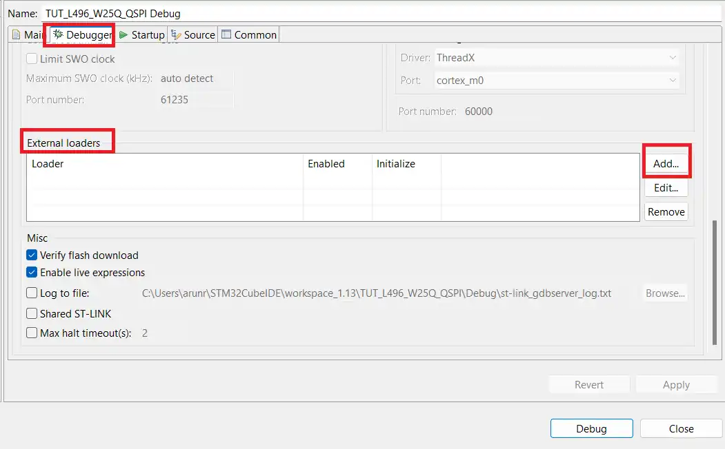
The reallocation can not happen until we use the external loader, so we will now add the loader to the debug configuration.
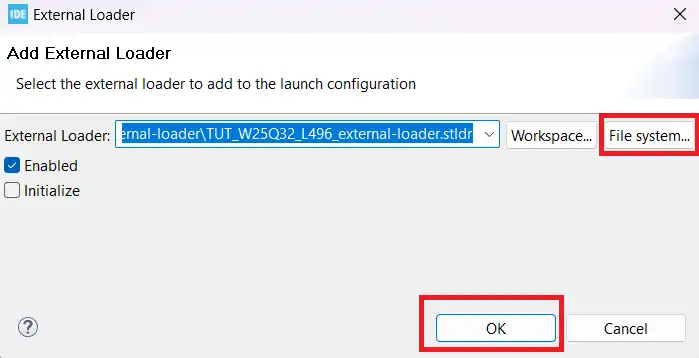
Open the debug configuration, goto the debugger tab, scroll down to external loaders, and click add.
Now browse the external loader we created, and debug the project.
Result
Below is the image showing the data in the Read buffer.
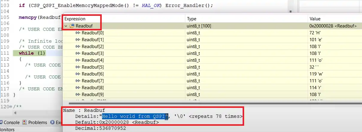
You can see we got the same data that we stored in the writebuf. We achieved the result without even performing a write operation to the QSPI memory. This means the reallocation of the writebuf works as the data has been reallocated to the QSPI memory.
We can use it to reallocate large files like images, audio files, or even the video files.
STM32 W25Q Flash Tutorials Series

W25Q Flash Series Part 2 – Read Data from Device

W25Q Flash Series Part 3 – How to Erase Sectors

W25Q Flash Series Part 4 – How to Program Pages
W25Q Flash Series Part 5 – how to update sectors

W25Q Flash Series Part 6 – Integers floats and 32bit Data

W25Q Flash Series Part 7 – QUADSPI Write, Read, Memory Mapped mode
W25Q Flash Series Part 9 – SPI Flash Loader


I’m using a STM32H743 with a W25Q64JV flash part. I have qspi drivers that work fine in my application for write, read, erase and in memory mapped mode, the drivers file almost exactly match the example files of this project. The tests described here in the main.c for write, erase, and memory mapped pass as well.
When I create the .stldr and include it in the STM32Programmer it connects and then when I initially select the 0x90000000 address it reads the contents as expected but when I press the READ button it fails (Error: Data read failed) and when I try to program the erase fails (Error: failed to erase memory). Any ideas of what could be happening?
There might be issues in the stldr project. Check that project again.. every detail of it
if the initial read works fine when connecting but pressing the READ button fails is it somehow exiting memory mapped mode for this to happen. I only see QSPI_Abort() before a write or before an erase so not sure how this would happen. I’m using the Loader_Src.c from the H7 folder in the repository, which is the same as the example project I downloaded from this page.
Were you able to solve this? I have the exact same problem…
Same problem Here. Were you guys able to solve this?
In my case I coded the QSPI functions as I’m using W25Q256JV and I want them to use 1-4-4 with 4Byte addressing.
My code passes the test easily, but for some reason I can’t use the .stldr.
I made sure to be able to read/write/erase with my own driver, but on Cube Programmer I can’t erase/write or even read the memory values.
What is the voice-over program you use to dub your videos? It is pretty nice.
Amazon Polly Neural