
Home ▸ STM32 Tutorials ▸
Updated On: April 12, 2026
Modbus #5. STM32 as Slave || Read Coils and Inputs
This is the 5th Tutorial in the Modbus Series, and today we will start the STM32 as a slave Device. This tutorial will cover how the STM32 as a slave device will send a response to the queries regarding reading Coils and Discrete inputs.
We will cover the function codes FC01 and FC02 in this tutorial, but from the slave prospective.
I have already covered the connection parameters in the previous tutorial, and we will continue with the same connection. in fact this is going to be the same project with a few additions in the modbusslave.c file.
I have just added the functions for reading coils and inputs in the modbusslave.c file. The rest of the project is pretty much the same as the previous one.
VIDEO TUTORIAL
You can check the video to see the complete explanation and working of this project.
The Master Software
I am using the simply modbus master software, which can be downloaded from https://www.simplymodbus.ca/download.htm
The software is shown below
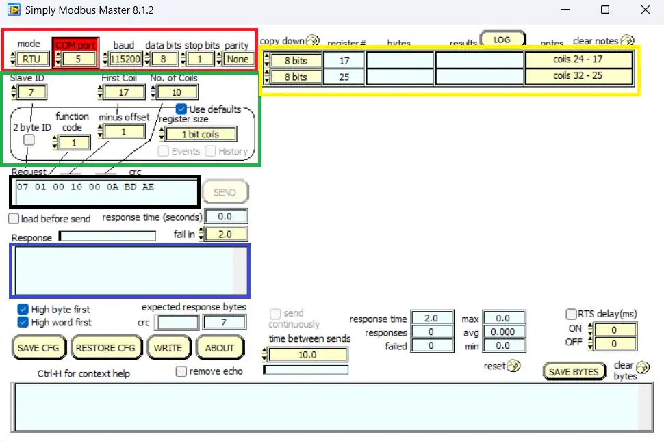
- Here in the RED BOX we have the serial configuration. It is same as what we configured in the cubeMX.
- The 115200-8-N-1 configuration
- The GREEN BOX contains the slave ID, The start Coil, the number of Coils master wants to Read, the function code and the Coil size.
- The BLACK BOX contains the query to be sent by the master. It is based on the setup we did in the Green box.
- The BLUE box contains the response received by the master. It will update once the slave send some response.
- The YELLOW BOX contains the Coils master has requested the values for. These will update once the slave send the data.
Some insight into the CODE
As I mentioned, I am using the same project as previous one, I will only explain the code related to the coils and inputs. You can check the detailed explanation in the previous tutorial.
The readcoils function:
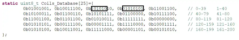
Below is the coils Database for 200 coils defined in the modbusslave.h file.
static uint8_t Coils_Database[25]={
		0b01001001, 0b10011100, 0b10101010, 0b01010101, 0b11001100,    // 0-39    1-40
		0b10100011, 0b01100110, 0b10101111, 0b01100000, 0b10111100,    // 40-79   41-80
		0b11001100, 0b01101100, 0b01010011, 0b11111111, 0b00000000,    // 80-119  81-120
		0b01010101, 0b00111100, 0b00001111, 0b11110000, 0b10001111,    // 120-159 121-160
		0b01010100, 0b10011001, 0b11111000, 0b00001101, 0b00101010,    // 160-199 161-200
};uint8_t readCoils (void)
{
uint16_t startAddr = ((RxData[2]<<8)|RxData[3]); // start Coil Address
uint16_t numCoils = ((RxData[4]<<8)|RxData[5]); // number to coils master has requested
if ((numCoils<1)||(numCoils>2000)) // maximum no. of coils as per the PDF
{
modbusException (ILLEGAL_DATA_VALUE); // send an exception
return 0;
}
uint16_t endAddr = startAddr+numCoils-1; // Last coils address
if (endAddr>199) // end coil can not be more than 199 as we only have record of 200 (0-199) coils in total
{
modbusException(ILLEGAL_DATA_ADDRESS); // send an exception
return 0;
}The initial part of the readcoils function is same as that we saw in the readHoldingRegisters function.
- We find the Address of the start coil by using the RxData[2] and [3].
- Then we find the number of coils requested by the master. This information arrives in RxData[4] and [5].
- As per the standards, the master can request a maximum of 2000 coil data at once. So if the master requests more than that, the slave will send an exception regarding ILLEGAL_DTATA_VALUE
- Next we will calculate the the address of the last coil (endAddr). Since I have defined the database for only 200 coils (0-199), if this end coil address exceeds 199th coil, the slave will send an exception regarding ILLEGAL_DATA_ADDRESS.
If everything is okay so far, we will load the data into the TxData buffer and send the response to the master.
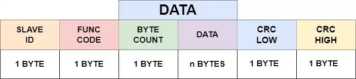
In the next part of the function, we will prepare the response and send it to the master. The slave response structure is shown below
	//reset TxData buffer
	memset (TxData, '\0', 256);

	// Prepare TxData buffer

	TxData[0] = SLAVE_ID;  // slave ID
	TxData[1] = RxData[1];  // function code
	TxData[2] = (numCoils/8) + ((numCoils%8)>0 ? 1:0);  // Byte count
	int indx = 3;  // we need to keep track of how many bytes has been stored in TxData Buffer

	int startByte = startAddr/8;  // which byte we have to start extracting the data from
	uint16_t bitPosition = startAddr%8;  // The shift position in the first byte
	int indxPosition = 0;  // The shift position in the current indx of the TxData buffer

	// Load the actual data into TxData buffer
	for (int i=0; i<numCoils; i++)
	{
		TxData[indx] |= ((Coils_Database[startByte] >> bitPosition) &0x01) << indxPosition;
		indxPosition++; bitPosition++;
		if (indxPosition>7)  // if the indxposition exceeds 7, we have to copy the data into the next byte position
		{
			indxPosition = 0;
			indx++;
		}
		if (bitPosition>7)  // if the bitposition exceeds 7, we have to increment the startbyte
		{
			bitPosition=0;
			startByte++;
		}
	}

	if (numCoils%8 != 0)indx++;  // increment the indx variable, only if the numcoils is not a multiple of 8
	sendData(TxData, indx);  // send data... CRC will be calculated in the function itself
	return 1;   // success
}I am going to read one bit at a time from the database and then copy it in the TxData buffer.
- First we will copy the slave ID, and then the function code.
- The TxData[2] contains the number of data bytes the slave is going to send.
- The data can be only sent in bytes, so even if the master requests to read 1 coil, the slave will send that 1 bit data packed in a byte format.
- The formula is used to calculate the number of bytes based on the number of coils requested by the master. It is explained in the video towards the end of this post.
- Then we will calculate the startbyte, the byte in database where the copying will start from, the bitposition, the shift in the startbyte, and the indexposition.
- Basically, we will shift the startbyte to the right by the “bitposition” value. For eg, if the start coil address is 13, our first bit will byte1, and in order to extract the 13th bit, we will shift this byte1 by 5 places to the right.
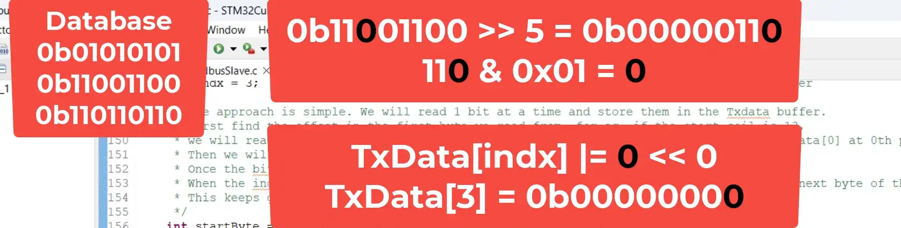
Once the Bit is extracted, we will shift it to the LEFT by the “indexposition” value, and add the result with the TxData[indx].
This will store the bit in the TxData buffer.
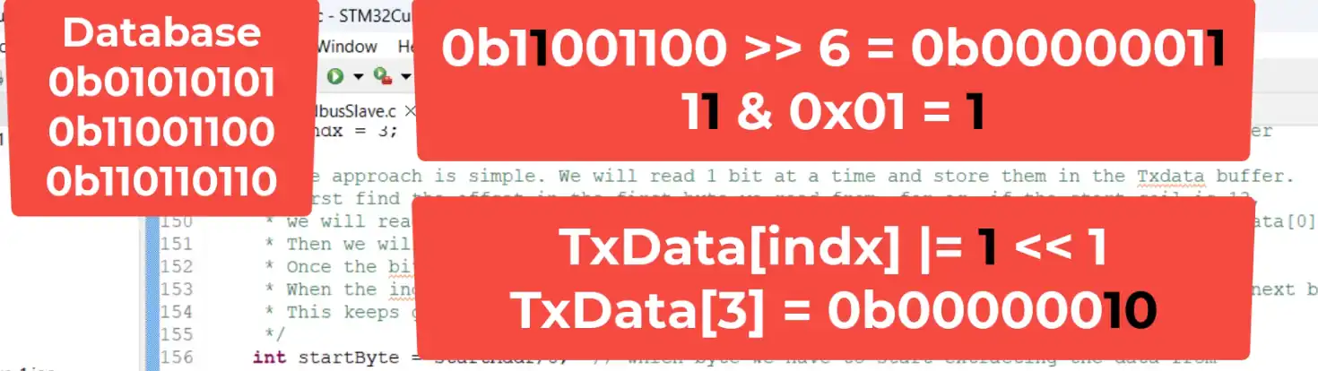
Then we will increment the bitposition and indxposition variables. Now the bitposition is 6 and indxposition is 1.
When we perform the same operation as above, the next bit is stored in the next position in the TxData buffer. This is shown below
We will increment the startbyte and indx variables, when the bitposition and indxposition is greater than 7.
Since we are extracting 1 bit at a time, the for loop continues for as many times as the number of coils requested by the master.
Finally we will send the data using the sendData function. The CRC will be calculated inside the function itself.
Result
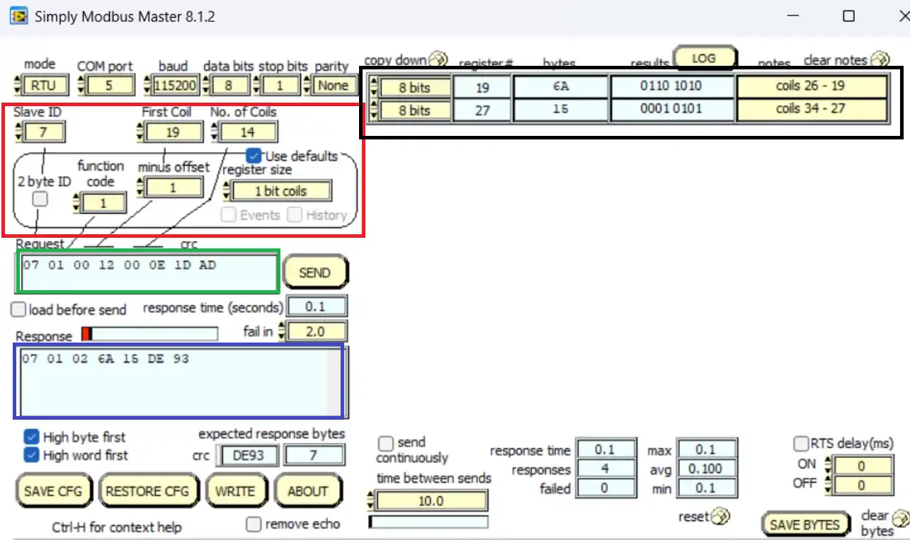
Above is the image of the master software sending the query and receiving the response from the slave device.
- Here the RED BOX contains the Slave ID (7), the start Address (19) and the number of coils to read (14)
- The GREEN BOX contains the query sent by the master in bytes format, based on the above configuration.
- The BLUE BOX is the response received by the master.
- The BLACK BOX contains the data received for the respective coils.
Since the master requested the data for 14 coils, the slave sent the 2 bytes for the same.
You can see the Coil data is same as what we stored in the database as shown below:
STM32 Modbus RTU Tutorial Series

Modbus #1. STM32 Master Reads Holding and Input Registers

Modbus #2. STM32 Master Reads Coils and inputs

Modbus #3. STM32 Master Writes single Coil and Holding Register

Modbus #3.1 STM32 Master Writes Multiple Coils and Registers

Modbus #4. STM32 as Slave || Read Holding and Input Registers

Modbus #6. STM32 as Slave || Write Registers

Modbus #7. STM32 as Slave || Writing Coils


hii Sir,
i can’t understand the connection of uart to modbus converter in this code. where RE+DE pin connect as like previous video a TX_EN pin.
Pls Help on this
I am not using the RS 485 in this setup. Since I have used the nucleo board, the controller is directly connected to the computer using the USB cable. This setup uses the uart to RS232.
If you want to use RS 485, you just need to modify the sendData () function as it was in the previous tutorials.
hi,
when you use UART2 ,You can connect to the PC through a USB cable without using the converter that also required a pin to enable the tx or rx mode.
ver video
https://www.youtube.com/watch?v=RjwfSm1kuy0&list=PLfIJKC1ud8ggRvaEsMjSEDazoBAnY4MUv&index=12
minuto 1:40
I just realized that I was using the usb instead of the converter when I started video 5 and I remembered that I never configured PA8 and it worked hahahaha