Communicate with PCF8574 using I2C
This is the 6th tutorial in the AVR series using the xplained mini development board, and today we will continue with the I2C Master series. In this series, we will developing the code for the I2c master across few tutorials, covering the Write and Read operations to the slave device.
We have already covered how to configure and initialize the I2C, and how to write the data to the dummy slave device in the previous tutorial. In today’s tutorial, we will connect an actual slave device, PCF8574, to the I2C bus. We will see how to communicate to this device and in the end we will control few LEDs connected to the output of this device.
VIDEO TUTORIAL
You can check the video to see the complete explanation and working of this project.
The PCF8574
I chose the PCF8574 as the slave device as its easily available in the market. Also it is a very easy device to get started with the I2C. the PCF8574 is a 8 bit IO expander for the I2C bus, which means we can control 8 outputs on this device using the I2C.
It is generally used to connect to the LCD, thus changing the pins requirement for the LCD from 11 pins to only 2 pins. We will see its application with the LCD 1602 display in the next tutorial.
Below is the image showing the Block Diagram of the device.
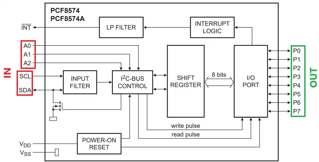
As shown above, the device has 8 output Pins (P0-P7) and 3 Input pins (A0-A2) along with the SCL and SDA pins. The Input pins (A0-A2) are used to modify the address of the device in case 2 or more devices are connected to the same I2C bus.
The address of the device is shown in the image below.
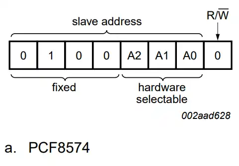
The 7bit address has the 4 fixed bits (0100) and the 3 modifiable bits (A2 A1 A0). The R/W bit is set by the master depending on whether it wants to Read or Write the data. The Address of the PCF8574 can vary between 0x20 (A2=A1=a0=0) and 0x27 (A2=A1=A0=1).
The module i am using for this tutorial has all the address bit (A2-A0) set to 1 by default, so the 7 bit slave address will be 0x27. You can see it in the connection diagram below.
Connection
Below is the image showing the connection between the PCF8574 module and the MCU.
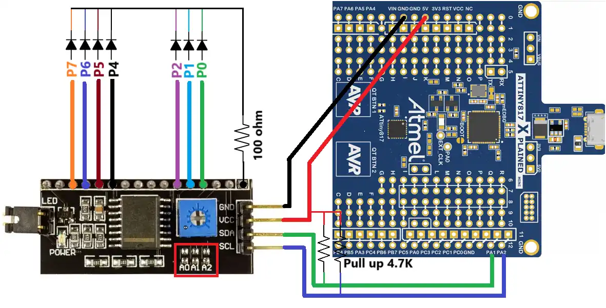
The Red block shows the address pins (A2-A0) and beside them are the ground pins. The address can be changed by connecting the respective pin to the ground. Right now none of them is connected, so all the address pins are set to 1.
The 7 LEDs are connected to the output of the module. This module is specifically used to connect to the LCD, so we don’t have the access to the pin P3.
The SCL and SDA pins are connected to the respective pins on the MCU, and the lines are pulled up to the VCC using 4.7K resistance. The Module is powered with 5V from the MCU itself.
The Code
We will use the same I2C library that we used in the previous tutorial. The only changes will be in the main file as we need to send some particular data to turn these LEDs ON. Below is the code from the main file.
uint8_t datatosend[] = {0x01, 0x02, 0x04, 0x10, 0x20, 0x40, 0x80};

int main(void) {
    clkInit();
    I2C_Init();
    _delay_ms(100);
    while (1) {
        for (int i=0; i<7; i++)
        {
            I2C_Write(0x27, &datatosend[i], 1);
            _delay_ms(1000);
        }

    }
}The datatosend array now contains the data to turn ON one LED at a time. To do so, we simply need to write a 1 to the particular output pin (P0-P7). Since we don’t have the access to P3, the data for the same (0x80) is excluded from the array.
In the while loop, we send the data to the slave address 0x27. We are sending 1 byte of data at a time, so only one LED will remain ON for a second.
Result
Below is the gif showing the LEDs.

You can see the LEDs are turning ON one by one, just as we programmed them to do.
We will also take a look at one of the I2C frames. This is shown below.
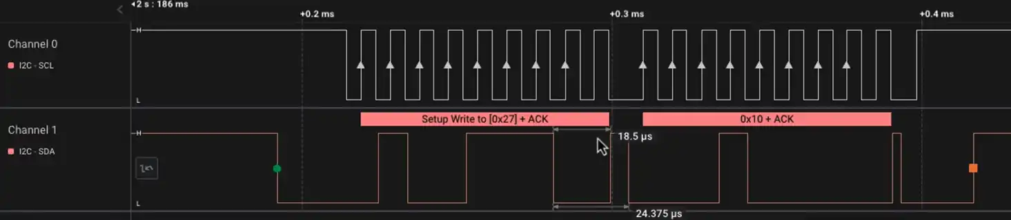
The data shown in the I2C frame is as follows:
- The START bit is represented by the Green dot.
- The master then send the device address (0x27) with a write request.
- The slave receives the address and sends the ACK response.
- The master then sends the data (“0x10“) and receives the ACK response again.
- In the end the master send the STOP condition, which is represented by the orange dot.

