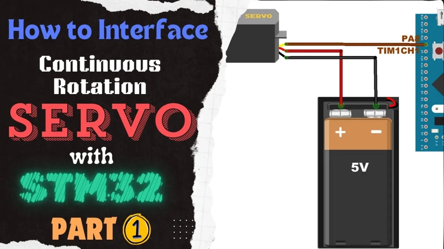
Learn to interface a continuous‑rotation servo with STM32 using PWM. This tutorial Covers CubeMX timer setup, wiring, pulse‑width control (0.5–2.5 ms) for RPM & direction. The project is available to download at the end of the post.
Recommended Resources:
A servo motor needs a PWM signal in order to work. You should take a look at the PWM tutorial covered earlier.
VIDEO TUTORIAL
You can check the video to see the complete explanation and working of this project.
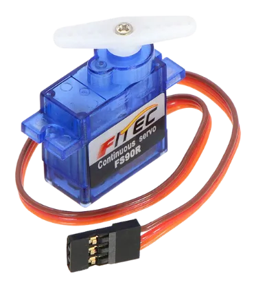
Introducing Continuous-Rotation Servo Motor
A continuous-rotation servo motor (also known as a 360-degree servo) is a type of servo that can rotate continuously in either direction, unlike standard servos which have limited angular movement. It is controlled using PWM signals, where the pulse width determines both the direction and speed of rotation. These motors are commonly used in robotics, mobile platforms, and automated systems where precise speed and direction control are needed rather than angle positioning.
Some of its important features are:
- Full 360° rotation with bidirectional control
- Speed and direction controlled via PWM signal
- Requires only one signal wire for control
- Ideal for wheeled robots, conveyor systems, and continuous motion tasks
All kind of servo motors have the following three wires:
- Black/Brown ground wire.
- Red power wire (around 5V).
- Yellow or White PWM wire.
HOW CONTINUOUS SERVO WORKS
Continuous Servos rotates continuously through 360°. Their RPM and direction can be varied depending on the width of the pulse. Basically you need to keep the pulse (+5v) high for a particular amount of time. Some of the important timings are mentioned below.
- 0.5 milliseconds pulse width will rotate the servo at maximum RPM in clockwise direction.
- 1.5 milliseconds pulse width will stop the rotation.
- 2.5 milliseconds pulse width will rotate the servo at maximum RPM in counterclockwise direction.
As the Pulse increases from 0.5ms to 1.5ms, the RPM decreases in the clockwise direction. Then the motor stops when the pulse width is 1.5ms. When the pulse width further increases from 1.5ms to 2.5ms, the RPM increases in the counterclockwise direction.
The period of the PWM signal must be 20ms or we can say the frequency of the signal must be 50 Hz.
CUBEMX CONFIGURATION
Clock Configuration
The clock configuration for the STM32F103C8T6 is shown below.
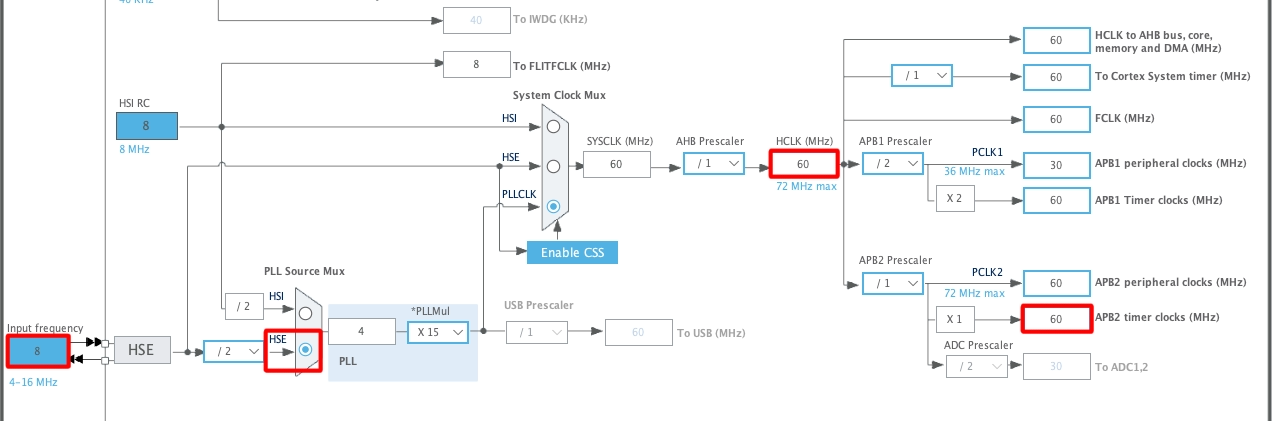
- External Crystal (8MHz) is used to provide the clock via the PLL.
- The system is running at 60MHz.
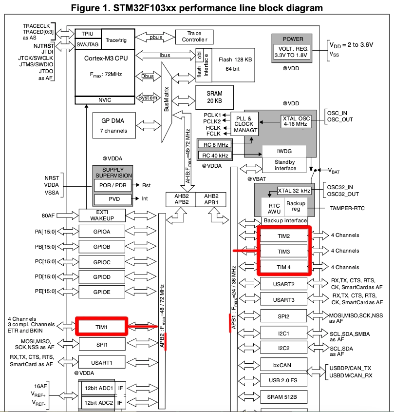
- I am going to use the TIM1 for the PWM, which is connected to the APB2 Bus (Check this Image).
- The APB2 Timer clock is at 60MHz right now.
PWM Configuration
The TIM1 configuration is shown below.
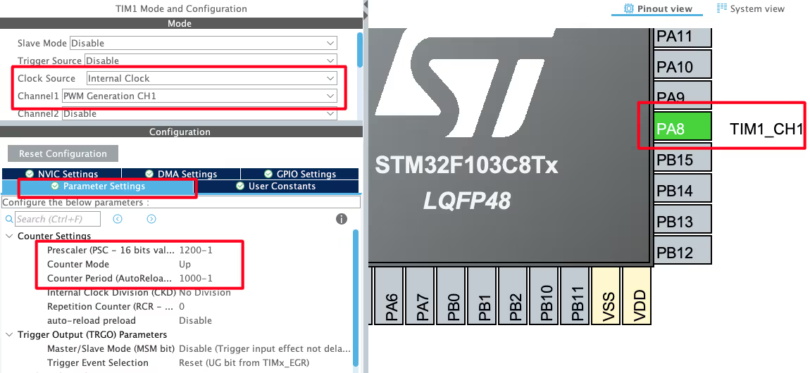
- Select the PWM channel for the Timer, I am using Channel 1.
- Set the Clock source as internal clock, which is at 60 MHz.
- Pin PA8 is set as the PWM output Pin and we will connect it to the Servo Motor Signal pin.
The output Frequency of the PWM signal depends on 3 parameters, Timer Clock, ARR and Prescaler.

Out of these parameters, the Timer Clock will remain constant at 60MHz throughout the project. We want to generate the PWM signal with the Frequency of 50Hz. To do so, I am setting the Prescaler and ARR values as shown below.

Here the Prescaler value is not as important but the ARR plays a very important role. We will see this in details below.
Note that the Pres and ARR input values must be 1 less than the actual values. This is because the library add a 1 to this value at the register level, so we must keep it 1 less than the value we want to pass.
HOW TO SET THE PULSE
The servo motor responds for the pulse width of 0.5ms to 2.5ms. Also the pulse period is 20ms, so in terms of Duty%, the pulse width for the extreme ends can be calculated as shown below.

Now keeping the above duty cycles in mind, our choice of ARR affects the variations available for the pulse width.
For eg- Let’s assume we choose the ARR of 100.
- To generate a duty cycle of 2.5%, we need to set the value 2.5 to the Compare Register (CCR).
- Similarly to generate a duty cycle of 12.5%, we need to set the value 2.5 to the Compare Register (CCR).
This will give us only 10 steps (12.5 – 2.5) of variations between the extreme positions. Each step will result in a large variation in the RPM of the motor.
Here in the project I chose the ARR value of 1000. The Compare Register value depends on the ARR, so the values for the Duty cycles are as follows:

This set up will result in 100 steps (125 – 25) of variations between the extreme ends. We will have more variations for the motor RPM.
WIRING DIAGRAM
Below is the image showing the connection between the STM32F103C8 and the Continuous servo motor.
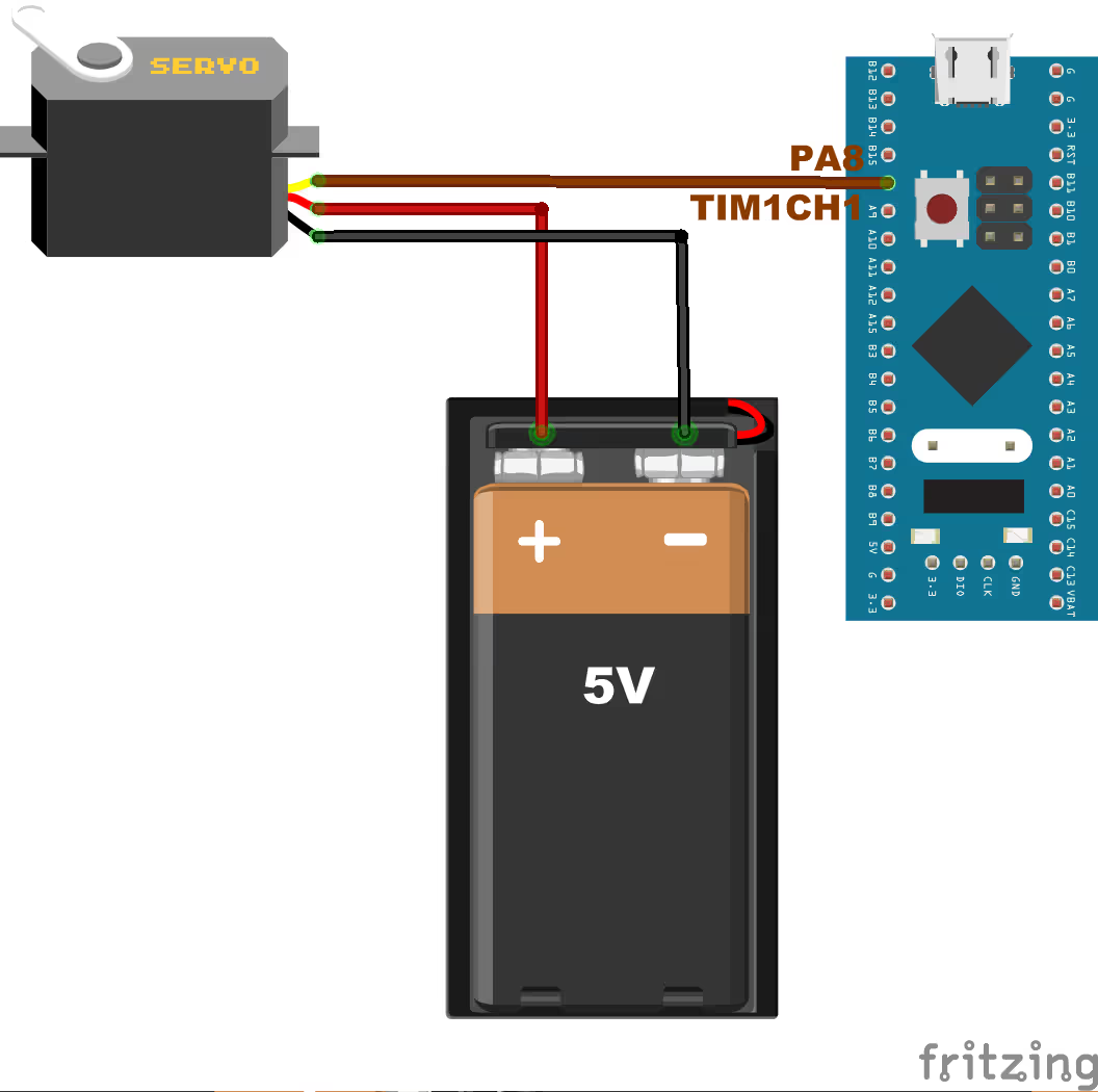
I am powering the motor using a 5V battery.
- Black/Brown ground wire from the motor connects with the Ground of the battery.
- Red power wire from motor connects to the VCC of the battery.
- Yellow or White PWM wire from motor connects to the pin PA8 of the STM32. This is TIM1 CH1, which we have configured as the PWM out pin.
THE CODE
int pulse = 75;
int main ()
{
  ....
  HAL_TIM_PWM_Start(&htim1, TIM_CHANNEL_1);
  while (1)
  {
    while (pulse <=125)
    {
       __HAL_TIM_SET_COMPARE(&htim1, TIM_CHANNEL_1, pulse);
       pulse++;
       HAL_Delay(250);
    }
    while (pulse >= 25)
    {
       __HAL_TIM_SET_COMPARE(&htim1, TIM_CHANNEL_1, pulse);
       pulse--;
       HAL_Delay(250);
    }
  }
}We will first define a pulse variable with initial value of 75. This value corresponds to the pulse width of 1.5ms and the motor stops at this point.
In the main function start the Timer in the PWM mode. I am using Timer 1 with Channel 1 to generate the PWM signal.
In the while loop, we will run 2 separate while loops. Remember that the pulse value is at 75 right now.
- While the pulse value is less than 125, we will keep increasing the value every 250ms.
- The new value will be passed to the Compare Register (CCR), so that the motor can respond according to it.
- When the pulse value reaches 125, the while loop will exit.
The pulse value is 125 right now. A second while loop will run at this point.
- While the pulse value is greater than 25, we will keep reducing it every 250ms.
- The new value will be passed to the Compare Register (CCR), so that the motor can respond according to it.
- When the pulse value reaches 25, the while loop will exit.
Basically we are varying the pulse value between 25 and 125. This will vary the pulse width from 0.5ms to 2.5ms.
RESULT
Below is the video showing the behaviour of the motor for the above code.
As you can see in the video above
- The RPM increases in the counterclockwise direction when the pulse value increases from 75 to 125.
- The RPM is maximum when the pulse value is at 125 and it decreases in the counterclockwise direction when the pulse value decreases from 125 to 75.
- The RPM increases in the clockwise direction when the pulse value decreases from 75 to 25.
- The RPM is maximum when the pulse value is at 25 and it decreases in the clockwise direction when the pulse value increases from 25 to 75.
This is as we expected when we programmed the STM32.
PROJECT DOWNLOAD

