Updated On: March 23, 2026
How to Create a 48-Bit Counter by Cascading STM32 Timers
In many embedded applications, a standard 16-bit timer is not enough. With a maximum count value of 65,535, the counter can overflow very quickly, especially when working with high-frequency clocks or when measuring very slow signals over long periods. To overcome this limitation, STM32 timers can be cascaded together to effectively create a much wider counter.
In this tutorial, we will learn how to combine multiple 16-bit STM32 timers to build a 32-bit and even a 48-bit counter using hardware synchronization. By configuring one timer to act as a clock source for another, we can significantly extend the counting range without using external components. This method is especially useful for wide-range frequency measurement and long-duration timing applications. We will go step by step through the configuration and understand how the cascading mechanism works internally.
How Cascading STM32 Timers Creates a 48-Bit Counter
A standard STM32 general-purpose timer typically has a 16-bit counter. This means it can count from 0 to 65,535 and then it overflows back to zero. When working with high-speed clocks, this overflow can happen very quickly, limiting the measurable range.
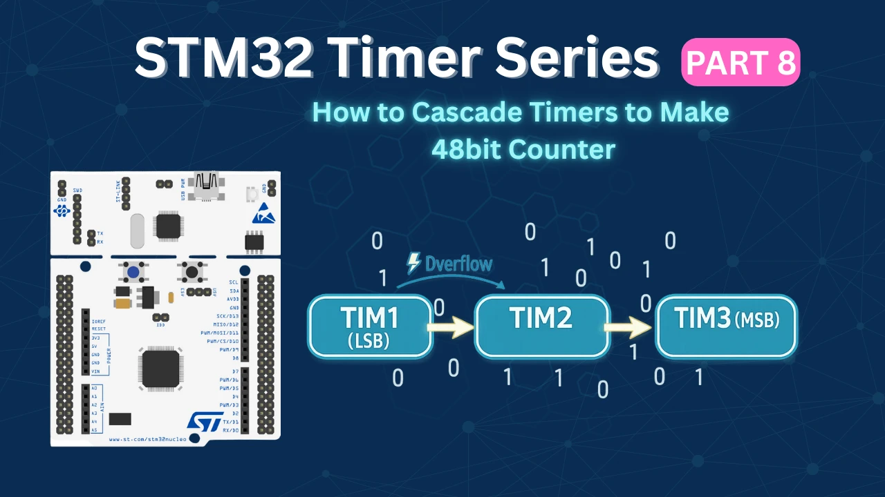
To extend the counting range, we connect multiple timers in series so that:
- The first timer counts at the base clock frequency.
- When it overflows, it generates an update event.
- That update event acts as a clock source for the second timer.
- When the second timer overflows, it clocks the third timer.
In this configuration:
- Timer 1 (LSB – Least Significant Timer) counts every clock pulse.
- Timer 2 (Middle Timer) counts the number of overflows from Timer 1.
- Timer 3 (MSB – Most Significant Timer) counts the number of overflows from Timer 2.
Effectively, the timers form a hardware counter chain, where each overflow shifts the count into the next higher stage — just like how multi-byte numbers work in software.
If each timer is 16-bit:
- Two cascaded timers → 32-bit counter
- Three cascaded timers → 48-bit counter
The total count value can then be reconstructed in software as:
Combined_Count = (TIM3 << 32) | (TIM2 << 16) | TIM1
This method allows us to measure extremely long time durations or very slow frequencies without losing precision, and most importantly, it works entirely in hardware with minimal CPU overhead.
For the purpose of the application, I will combine the 2 16bit timers to make a 32 bit counter, and use this counter to measure the wide range of frequencies. It will overcome the disadvantage of using a 16 bit counter, where we could only measure up to a certain bandwidth because of the counter size.
Similarly you can combine 3 16bit timers to make a 48bit counter, or 4 timers to make 64bit counter.
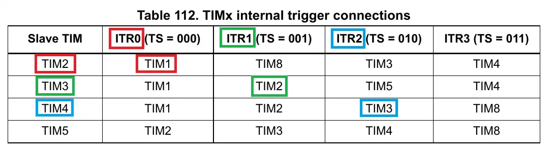
In this tutorial, I am going to use 2 timers, TIM1 and TIM3. TIM3 is the slave to TIM1 and is being controlled by the trigger ITR0. This is as per the internal trigger connection table in the F446RE reference manual.
When the timers are used in the slave mode (External Clock mode), the output of the master timer will be used as the input clock for the slave timer. By doing so, the APB clock is still running at max clock speed and so does the master timer’s counter. But the slave timer slows down, which helps us measure the lower frequencies.
STM32CubeMX Configuration
In this section, we will enable the required timers, set one timer as the master, configure the others in external clock mode, and establish the internal trigger connections needed to build the 48-bit counter.
Clock Configuration
The image below shows the clock configuration for this project.
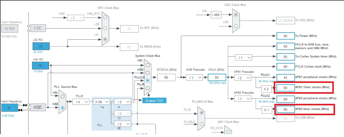
Here I have configured the external crystal, which is 8 MHz, to provide the clock such that the system will run at 90 MHz. This is to make sure that both the APB timer clocks have the same speeds and so all the timers will have the same base clock.
Master Timer Configuration
The image below shows the configuration for the TIM1 (Master Timer).
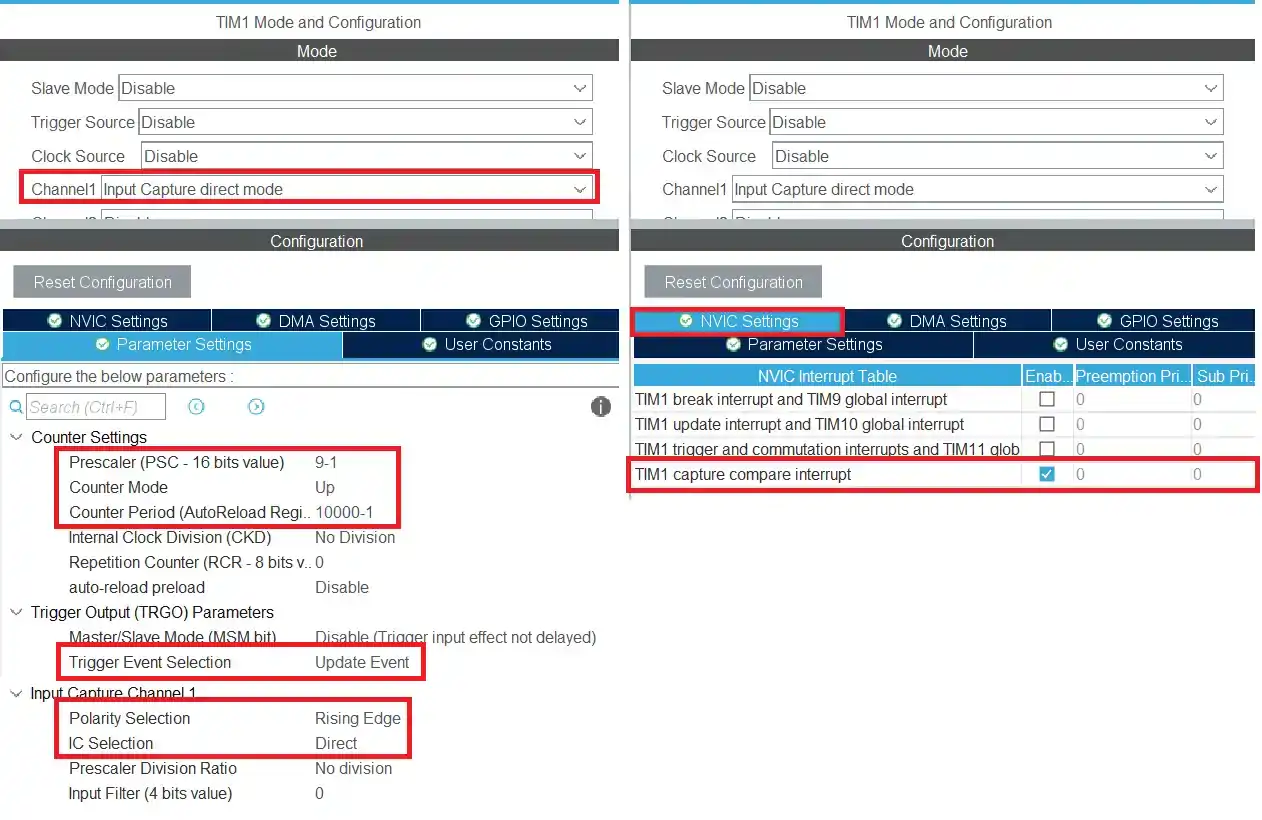
The Timer configuration is explained below.
- I have enabled the input capture on the channel 1 to measure the input signal.
- The timer is clocked by the APB clock, so the base frequency is at 90MHz.
- Using the prescalar of 9 will bring down the frequency to 10MHz.
- This 10MHz is also the counter 1’s Frequency. Basically the counter 1 will count at this rate.
- The ARR is set to 10000. This makes the counter 1’s period equal to 1ms. (check the image below)
- The trigger event selection is set to update event, so that we can cascade another timer with this.
- The input capture configuration is kept to default, i.e. capture on rising edge. Also the interrupt for the input capture has been enabled.
The TIM1’s output frequency will be equal to 1KHz. This will be used as the base clock for the slave timer.

Slave Timer configuration
The image below shows the configuration for Timer 3 (Slave timer).
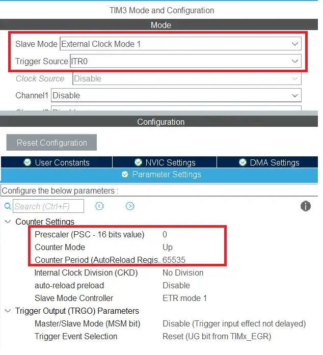
TIM3 is the slave to the TIM1.
- I have set the slave mode (External Clock Mode 1), and the Trigger source is set to ITR0.
- When the Update Event from the master timer is combined with the External Clock Mode 1, the output of the master timer is used as the clock for the slave timer.
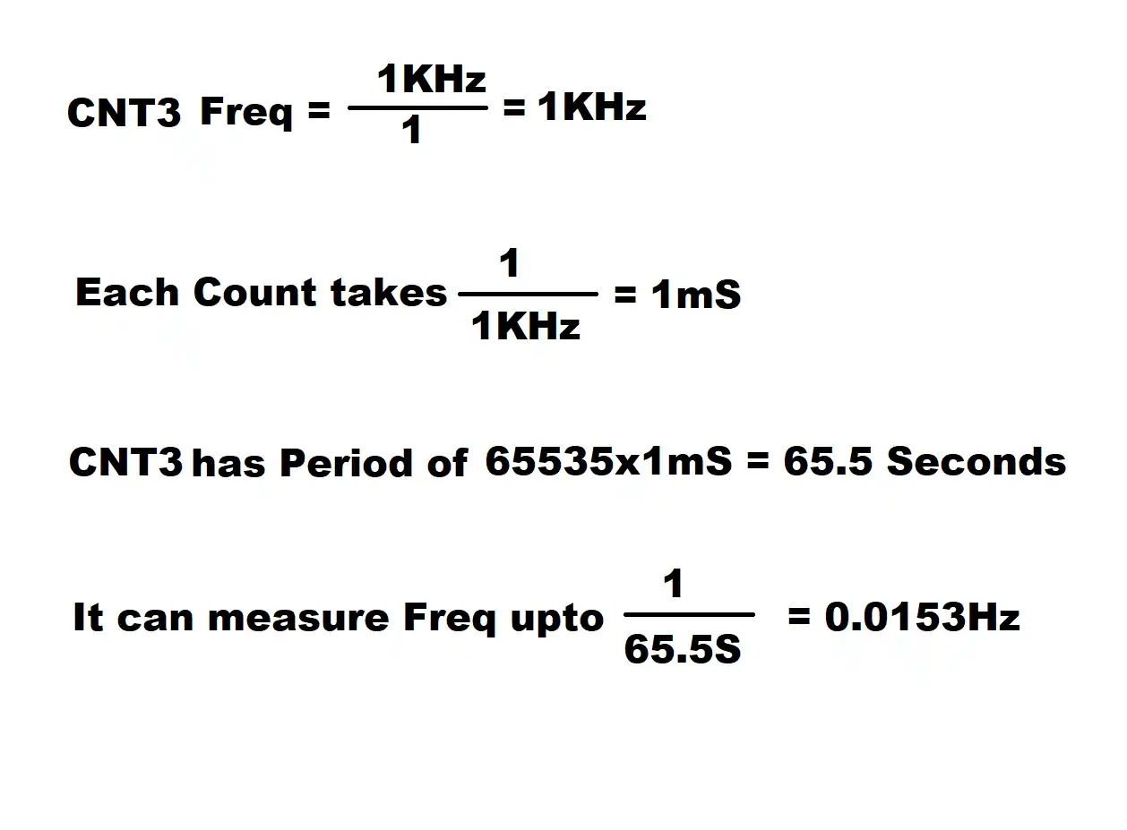
- Since the prescalar is set to 1, the counter 3 will run at 1KHz, so each count take 1ms.
- The ARR is set to 65535. This makes the counter 3 period equal to 65 Seconds.
So by using the combination of these 2 counters, we can measure the Frequencies from 10MHz(Theoretically) to 0.015Hz.
STM32 HAL code to Cascade Timers
In the main function, we will start the TIM1 in the input capture interrupt mode.
  /* USER CODE BEGIN 2 */
  HAL_TIM_IC_Start_IT(&htim1, TIM_CHANNEL_1);
  HAL_TIM_Base_Start(&htim3);
/* USER CODE END 2 */Also we will simply start the TIM3 so that it’s counter can also count.
Once the rising edge of the input signal is detected, the Input capture callback will be called. We will write the rest of the code inside it.
void HAL_TIM_IC_CaptureCallback(TIM_HandleTypeDef *htim)
{
	if (htim->Channel == HAL_TIM_ACTIVE_CHANNEL_1)
	{
		if (Is_First_Captured==0) // if the first rising edge is not captured
		{
			TIM1->CNT = 0;
			TIM3->CNT = 0;
			Is_First_Captured = 1;  // set the first captured as true
		}

		else   // If the first rising edge is captured, now we will capture the second edge
		{
			counter1 = TIM1->CNT;
			counter3 = TIM3->CNT;

			frequency = ((float)10000000)/((counter3*10000)+counter1);

			Is_First_Captured = 0; // set it back to false
		}
	}
}- Inside the callback, we will first check if the detected edge is the first or the second edge.
- If it is the first edge, then we will reset both the counters and set the
is_first_capturedto 1 indicating that the first edge has been captured. - When the second edge arrives the callback will be called again.
- Here we will first read the counters of the respective timers.
- Now we will combine all the counters to make a final counter value.
- Each count in the counter 3 is equivalent of 10000 counts in counter 1.
- so to make them equal, we need to multiply the counter 3 with 10000.
- Now we have the final counter value in terms of the counter 1, so to calculate the frequency, we will divide the counter 1 clock by the counter value.
- Finally reset the
is_first_captured, so that the whole process can begin again.
Result of the Timer cascading
For the purpose of testing, I am using the NE555 module which can output different frequency ranges.
Although we are using multiple timers, only TIM1 is being used as the input capture mode. So there is only one input pin as shown in the image below
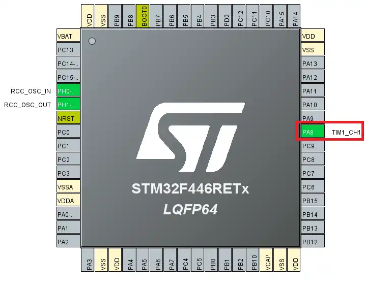
Below are the images showing the lowest and highest frequency
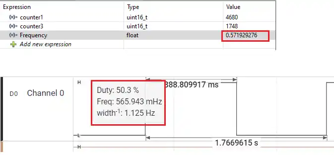
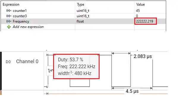
As shown in the image above, the STM32 can measure the 0.57 Hertz, as well as 222KHz. Even though we are configuring the TIM1 to run at 10MHz, the fact that it can measure the frequency as low as 0.5Hz is only possible by cascading the timers.
Although I didn’t use the 48bit counter in this tutorial, you can still use the same logic to make one.
You need to cascade 3 16bit timers with one timer clocking the second, and second clocking the third, TIM1->TIM2->TIM3.
With this configuration, the formula to calculate the frequency is shown below

Video Tutorial
STM32 48-Bit Counter – Cascading Timers Video Tutorial
This video explains how to create a 48-bit counter by cascading multiple STM32 timers. You’ll learn how to configure one timer as the base counter, set the next timers in External Clock Mode, and use internal trigger connections to build a hardware counter chain. The step-by-step walkthrough covers CubeMX configuration, HAL setup, and practical testing to demonstrate how combining 16-bit timers can significantly extend the counting range for wide-frequency measurement applications.
Watch the VideoConclusion
In this tutorial, we learned how to extend the counting capability of STM32 timers by cascading multiple 16-bit timers to create a 32-bit and 48-bit counter. By configuring one timer as the base counter and using its update event as the clock source for the next timer in the chain, we effectively built a hardware-based wide counter without requiring any external components. This approach allows the system to handle very large count values while keeping CPU involvement minimal.
Cascading timers is especially useful in applications such as wide-range frequency measurement, long-duration timing, and high-precision event counting. Instead of being limited by the 16-bit overflow constraint, we can combine timers to achieve significantly larger counting ranges with reliable hardware synchronization. With this technique, you can design more advanced timing systems in STM32 while maintaining accuracy and efficiency.
Browse More STM32 Timer Tutorials
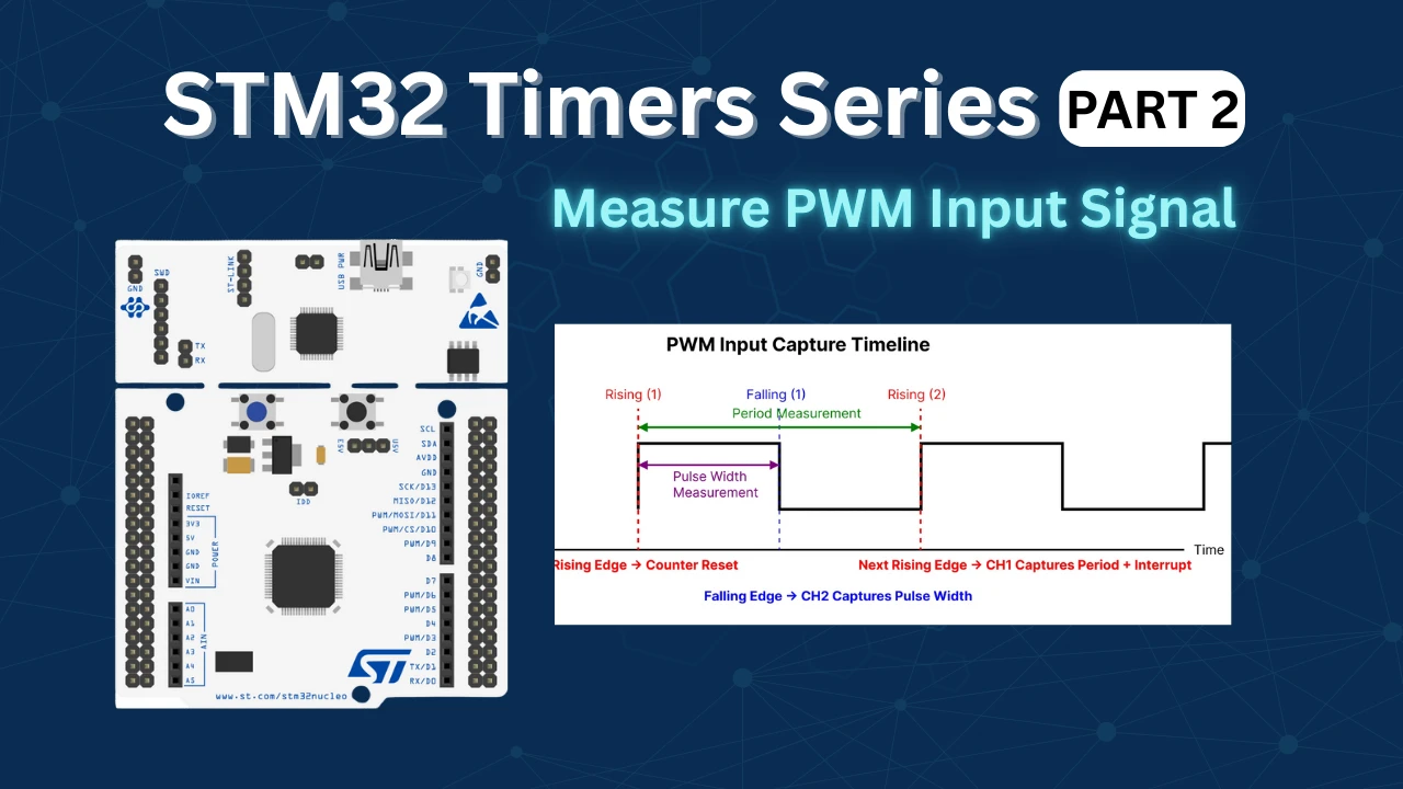
STM32 Timers (Part 2): How to Measure PWM Input Signal
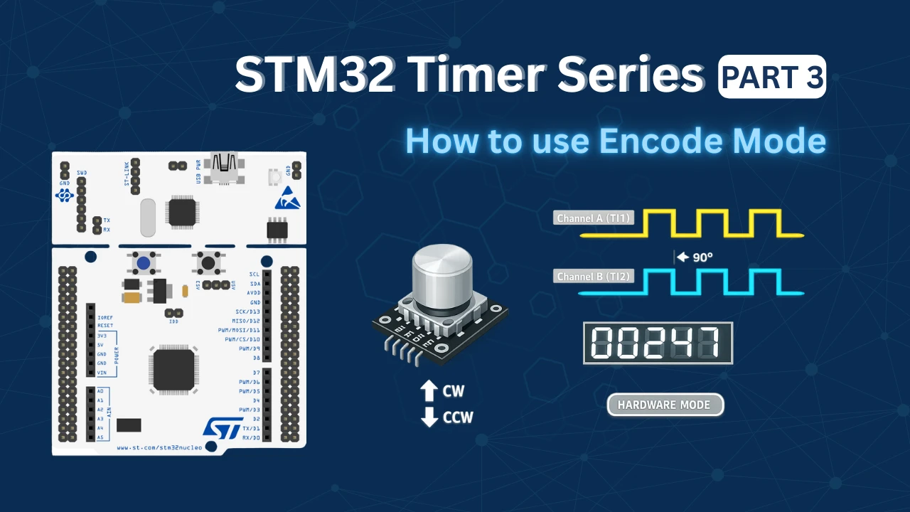
STM32 Timers (Part 3): How to use the Timer Encoder Mode
STM32 Input Capture: Measure Frequency & Pulse Width
STM32 Timer Synchronization: Slave Trigger Mode with CubeMX & HAL
STM32 Timers (Part 6): Timer Synchronization for 3-Phase PWM Generation
STM32 Timers (Part 7): Timer synchronization using Slave Reset mode
STM32 Timers (Part 9): One Pulse Mode (OPM) – Generate Precise Triggered Pulses with Delay and Width Control
STM32 Cascading Project Download
STM32 Cascading PWM FAQs


Hello,
Thank you very much, Sir.