How to Communicate using Single Wire || Half Duplex Mode
This is the 6th tutorial in the series on the UART peripheral of STM32 Microcontrollers. In this series we will cover different ways of transmitting and receiving data over the UART protocol. We will also see different UART modes available in the STM32 microcontrollers and how to use them.
In the previous tutorial of this series we saw how to send and receive the data over the UART using different methods. Although there was one thing common in all of them, and that was the use of 2 wires for the data transfer. We use the TX pin to transmit the data and the RX pin to receive the data and hence the MCU was able to transmit and receive data simultaneously.
In Half Duplex Mode, there is only one pin available for the transfer, the TX pin. Therefore the MCU can either act as as transmitter or receiver, but not both (simultaneously). Although we can achieve the transmission and reception by carefully designing the code.
In this tutorial we will cover the Half Duplex Communication between two STM32 MCUs. Both the MCUs will be put in the Receiver mode. We will use some kind of trigger signal to make one of the MCU as the transmitter and send data to another MCU. This way there will be only one transmitter on the line at a time.
Connection
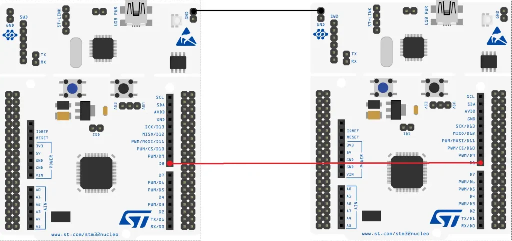
Below is the image showing the connection between the two STM32 controllers.
The pin PA9(D8) is the TX pin for the USART1. Both the TX pins are connected together.
The User Button (Blue) on both the boards will be used as the trigger signal to send the data over the UART. We will configure this button as the input pin in the cubeMX.
Note:- If you are using different power sources for both the MCUs, make sure to give them a common ground. Just connect either of the Ground pins of each MCU together.
CubeMX Configuration
Below is the image showing the cubeMX configuration for the USART1.
The UART is enabled with the default configuration. The baud rate of 115200 with 1 stop bit and no parity.
I am enabling the interrupt to receive the data in the interrupt mode.
Also make sure to enable the Pull-UP for the TX pin (PA9). This is needed to receive the data. Some of the MCUs (Like F103C8) do not have the Pull-up option here, so connect an external pull-up resistor to this TX line.
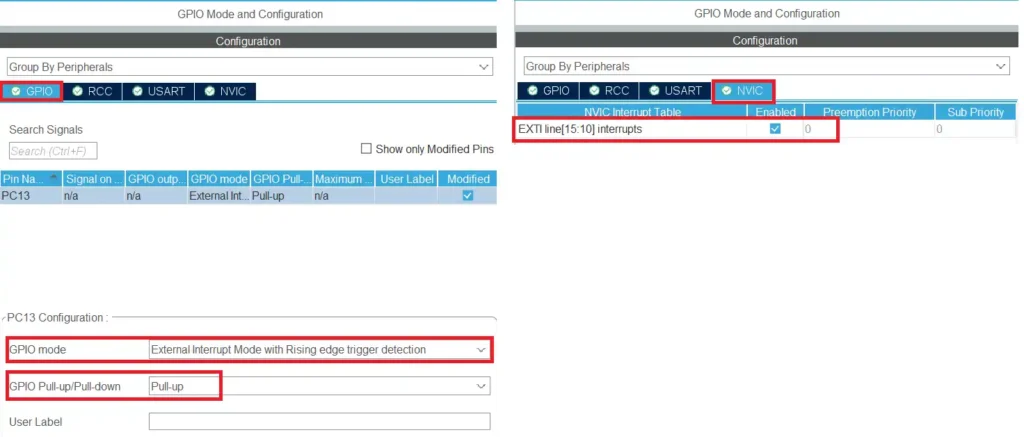
The User button on the nucleo-F446 is connected to the pin PC13. I have configured this pin as the External Interrupt (EXTI).
The pin is configured in the Pull-up mode, so initially it will be HIGH. When the button is pressed, the pin will be pulled low to the ground. When the button is released, it will be pulled HIGH again.
The trigger is set to the rising edge and hence it will generate an interrupt when the pin is released. Make sure to enable the interrupt in the NVIC Tab.
The code
the same code is used on both the microcontrollers. You can modify the data to be sent, so that it is easier to identify which MCU is sending it.
int main ()
{
  .....
  HAL_HalfDuplex_EnableReceiver(&huart1);
  HAL_UARTEx_ReceiveToIdle_IT(&huart1, RxData, 30);
  .....
Initially we will put both the MCUs in the Receiver mode, so the function HAL_HalfDuplex_EnableReceiver is used to do that. I am using the Receive to IDLE function to receive 30 bytes of data in the interrupt mode.
When all 30 bytes has been received or an IDLE line is detected before that, the Rx Event Callback will be called.
void HAL_UARTEx_RxEventCallback(UART_HandleTypeDef *huart, uint16_t Size)
{
	HAL_UARTEx_ReceiveToIdle_IT(&huart1, RxData, 30);
}
Inside the callback we will call the receive to idle function again so to maintain the continuity in the reception.
When the button is pressed on the nucleo board, the external interrupt is triggered and the EXTI callback is called.
int ispressed = 0;
int indx = 0;
void HAL_GPIO_EXTI_Callback(uint16_t GPIO_Pin)
{
	if (GPIO_Pin == GPIO_PIN_13)
	{
		if (ispressed == 0)
		{
			ispressed = 1;
		}
	}
}
Inside the callback we will first check if it is triggered by the pin PC13. Then we will check the value of ispressed variable. If the value is 0, we will set the variable to 1. This indicates that the button has been pressed.
We will send the data in the while loop. The sending process will be protected by the ispressed variable.
  while (1)
  {
	  if (ispressed == 1)
	  {
		  HAL_Delay(500);
		  indx++;
		  int len = sprintf((char*)buffer, "Hello from F446--%d\n", indx);
		  HAL_HalfDuplex_EnableTransmitter(&huart1);
		  HAL_UART_Transmit(&huart1, buffer,len,1000);
		  HAL_HalfDuplex_EnableReceiver(&huart1);
		  ispressed=0;
	  }
  }
The transmit code will only execute when the ispressed variable is set to 1, which means when the button is pressed.
Here we will first give a small delay so that we can prevent the button debouncing. The indx variable in incremented each time the button is pressed.
We will store the string to be sent in a buffer. The string will always contain an updated value of the indx variable. After storing the string, we will put the MCU in the transmitter mode, then send the data via the UART and put the MCU back to the Receiver mode.
Also reset the ispressed variable so that this loop doesn’t run again until the button is pressed.
Result
The same is used on another MCU as well. I have just changed the string, so that it is easier to identify which MCU has sent it.
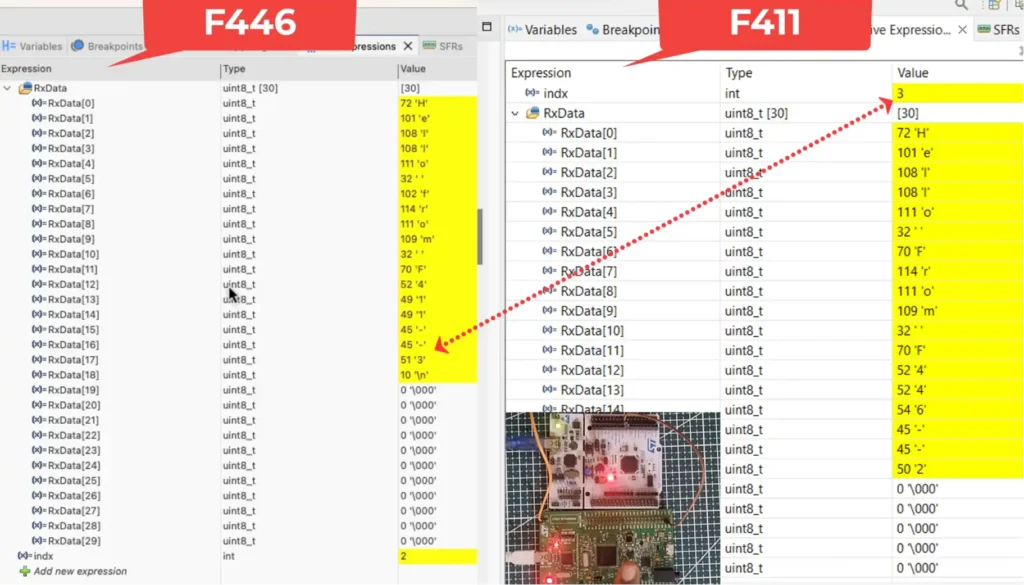
Below is the image showing the result of the above code.
You can see the index value of F411. The data received by the F446 has the same index value in it. This means the updated data has been received by the another MCU.
You can check out the video to see the detailed working.
