
Updated On: September 26, 2026
STM32 FreeRTOS Tutorial: CMSIS-RTOS V2 Configuration, Task Creation & LED Blink
Most STM32 projects begin with the same structure: a while(1) superloop containing multiple HAL_Delay() calls between tasks. This approach works for simple, single-purpose firmware. However, as soon as additional responsibilities are introduced, its limitations become clear. A single HAL_Delay(500) blocks all other operations, UART communication may lose data, sensor readings become delayed, and the code gradually turns into a complex mix of HAL_GetTick() checks and state-machine flags.
FreeRTOS addresses these issues at the architectural level. Instead of relying on a single loop to handle everything, it allows you to create independent tasks — each with its own stack, timing, and priority. The FreeRTOS scheduler rapidly switches between these tasks, ensuring efficient CPU utilization. When one task is waiting, others can execute, so the processor is not left idle when there is useful work to be done.
In this tutorial, you will learn why the superloop approach breaks down in multi-tasking firmware, and how FreeRTOS provides a structured solution. You will explore core concepts such as task states, the scheduler, and the Task Control Block (TCB). You will also understand what CMSIS-RTOS V2 is and why it is preferable to use it as an abstraction layer instead of calling FreeRTOS APIs directly.
This tutorial uses the STM32 Nucleo-L496ZG-P with STM32CubeMX and STM32CubeIDE. The same configuration steps apply to any STM32 Nucleo or custom board with minor pin adjustments.
This is Part 1 of the STM32 CMSIS-RTOS FreeRTOS series. The complete series:
- Part 2 — Multiple Tasks, Priorities & Preemption
- Part 3 — How to use Queues for inter-task communication
- Part 4 — Using Semaphores in CMSIS RTOS
- Part 5 — Using Mutexes in CMSIS RTOS
- Part 6 — Task Synchronization using Event Flags
- Part 7 — Software Timers in FreeRTOS
- Part 8 — FreeRTOS Stack Management
STM32 FreeRTOS CMSIS-RTOS V2 Tutorial — Video Walkthrough
This video covers the complete STM32 FreeRTOS setup workflow: superloop problems, FreeRTOS task model and scheduler internals, CMSIS-RTOS V2 abstraction layer, step-by-step CubeMX configuration including tick rate, heap size, SysTick/TIM6 time base separation, newlib reentrant, and GPIO setup, followed by writing the first osDelay()-based LED blink task on the STM32 Nucleo-L496ZG-P.
Table Of Contents
- Why STM32 Projects Need FreeRTOS
- STM32 FreeRTOS Concepts: Tasks, Scheduler & TCB
- CMSIS-RTOS V2 — Why Use It Instead of Raw FreeRTOS
- STM32 FreeRTOS CubeMX Configuration — Step by Step
- FreeRTOS Code Generated by CubeMX — Explained
- First STM32 FreeRTOS Task — LED Blink
- STM32 FreeRTOS — Frequently Asked Questions
Why STM32 Projects Need FreeRTOS
When we start learning STM32, most of us write code inside a simple while(1) loop. This is called the superloop approach. It works well in the beginning. I also used it for many small projects. But once the project grows, problems start appearing. Let’s understand why.
The Superloop + HAL_Delay() Problem
In a typical STM32 project, we often write something like this:
while(1) // Single infinite loop
{
  sensor_task();
  HAL_Delay(200);  // BLOCKS EVERYTHING
  display_task();
  HAL_Delay(500);  // BLOCKS EVERYTHING
  UART_task();
  HAL_Delay(1000); // BLOCKS EVERYTHING
}At first glance, this looks fine. But there is a big problem here.
HAL_Delay() blocks the entire CPU. When we call:
HAL_Delay(500);the CPU just waits there for 500 milliseconds. It does nothing else. During this time:
- UART cannot process incoming data properly
- Sensors may miss important readings
- Other time-critical operations get delayed
The CPU is busy waiting. It is not multitasking. In small projects, this seems fine. But in real embedded systems, this becomes a serious limitation.
As the number of tasks increases, maintaining proper timing becomes very difficult. We start adding counters, flags, and time checks using HAL_GetTick(). The loop becomes messy very quickly.
This is exactly the point where we should consider using RTOS in STM32 projects.
Why State Machines Don’t Scale Either
Now suppose we decide not to use HAL_Delay(). Instead, we try to make everything non-blocking using state machines.
We may write something like:
switch(state)
{
  case READ_SENSOR:
    if (HAL_GetTick() - prevTime >= 200)
    {
      Read_Sensor();
      prevTime = HAL_GetTick();
      state = UPDATE_DISPLAY;
    }
    break;

  case UPDATE_DISPLAY:
    // similar logic
    break;
}This works. But the code becomes harder to read. When we add:
- Multiple sensors
- UART communication
- Error handling
- Communication timeouts
The state machine grows very large. The code loses clarity. Maintenance becomes difficult. One small change can break the entire timing logic.
FreeRTOS as the Solution — One Task Per Job
We need a better way to:
- Run multiple tasks independently
- Avoid blocking the CPU
- Keep timing accurate
- Maintain clean and readable code
That solution is FreeRTOS. Instead of one big loop, we create separate tasks. Each task handles one job. The scheduler decides which task runs and when.
If one task waits, others continue running. This is why modern embedded systems prefer RTOS-based design over the traditional superloop approach.
STM32 FreeRTOS Concepts: Tasks, Scheduler & TCB
Before we start writing code, we should clearly understand what FreeRTOS actually is. Many beginners think it is just a library. But it is much more than that.
FreeRTOS changes the way our STM32 application runs internally. Instead of one infinite loop controlling everything, the control moves to a scheduler.
What Is a Real-Time Operating System (RTOS)?
A Real-Time Operating System (RTOS) is a lightweight operating system designed for embedded systems.
The keyword here is real-time. Real-time does not mean fast. It means predictable timing.
In embedded systems, we often need things to happen at precise intervals:
- Read a sensor every 10 ms
- Transmit data every 100 ms
- Respond to an interrupt immediately
An RTOS ensures that high-priority tasks run exactly when they should.
In a normal superloop Everything runs sequentially, Delays block the CPU and the timing becomes unpredictable.
Whereas in FreeRTOS:
- We create multiple tasks
- The scheduler decides which task runs
- Tasks can wait without blocking others
So instead of this:
while(1)
{
  Task1();
  Task2();
  Task3();
}We create independent tasks, and the RTOS runs them efficiently in the background.
What Is a FreeRTOS Task?
A task is like a small independent program inside your main program. Each task has:
- Its own stack
- Its own local variables
- Its own execution point
- Its own priority
When the scheduler switches from one task to another, it saves everything about the current task and restores the next one.
It feels like they are running at the same time. In reality, the CPU is switching between them very fast.
A typical task looks like this:
void StartTask(void *argument)
{
  for(;;)
  {
    // Task code
  }
}We intentionally write an infinite loop inside a task. If a task returns, FreeRTOS deletes it automatically. So every task must run forever unless we explicitly delete it. This structure keeps the system stable.
FreeRTOS Task States — Running, Ready, Blocked, Terminated
Every task in FreeRTOS can be in one of four main states.
- Running: This task currently owns the CPU. Only one task can be in the Running state at a time (in single-core STM32).
- Ready: The task is ready to run but waiting for the scheduler to give it CPU time. If two tasks are ready, the one with higher priority runs first.
- Blocked: The task is waiting for something:
- A delay (
osDelay) - A semaphore
- A queue
- An event
- Blocked tasks do not use CPU time. This is the biggest advantage over
HAL_Delay(). When we useosDelay(1000);Only that task is paused. Other tasks continue running.
- A delay (
- Terminated: The task has been deleted. It no longer exists in the system. In most applications, we rarely terminate task, rather we keep them running forever.
What Is a Task Control Block (TCB)?
Internally, FreeRTOS needs to store information about each task. This information is stored in something called a Task Control Block (TCB).
It stores:
- Stack pointer
- Task priority
- Current state (Running, Ready, etc.)
- Timing information
- Task name
How Context Switching Works
Whenever a context switch happens, the scheduler:
- Saves the current task’s CPU registers into its stack
- Updates its TCB
- Loads the next task’s stack pointer
- Restores its registers
All this happens in microseconds. We do not see it. But this is what makes multitasking possible.
CMSIS-RTOS V2 — Why Use It Instead of Raw FreeRTOS
Now that we understand what FreeRTOS is and how tasks work, the next question is: If we are already using FreeRTOS, why do we need CMSIS-RTOS?
FreeRTOS vs RTX5 vs ThreadX — The Portability Problem
In the embedded world, FreeRTOS is not the only RTOS available. There are several RTOS kernels:
- FreeRTOS
- Keil RTX5
- Azure RTOS ThreadX
- Zephyr and others
Each RTOS has its own API. For example:
In FreeRTOS, we create a task using: xTaskCreate()
In ThreadX, we use tx_thread_create() for the same
In Zephyr, k_thread_create() is used to create a task.
Now imagine this situation:
- Today, your project uses FreeRTOS
- Tomorrow, your company decides to move to ThreadX
- Or your client requires RTX5
If your entire application code uses native FreeRTOS APIs, you must rewrite everything. This is where CMSIS-RTOS V2 becomes very useful.
CMSIS-RTOS V2 as an Abstraction Layer
CMSIS stands for Common Microcontroller Software Interface Standard. CMSIS-RTOS is a standardized API defined by ARM.
- It does not replace FreeRTOS.
- It does not schedule tasks.
- It is not a kernel.
It is just an abstraction layer. Think of it like this:
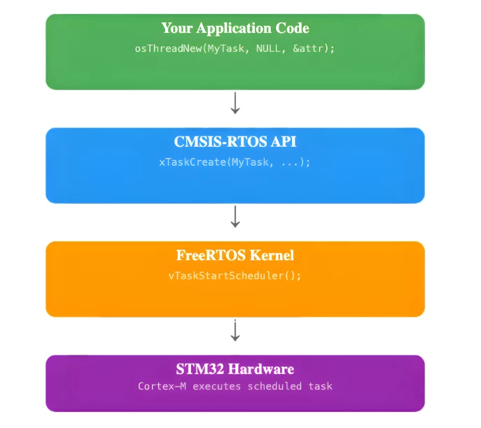
Your code calls CMSIS-RTOS functions like:
osThreadNew();
osDelay();
osSemaphoreAcquire();These functions internally call the native FreeRTOS or any other kernel’s functions. The CMSIS wrapper translates them to RTOS calls behind the scenes. This makes your application independent of the underlying RTOS.
CMSIS-RTOS V2 to FreeRTOS API Mapping Table
Let’s look at some direct mappings to understand this clearly.
| CMSIS-RTOS V2 | Native FreeRTOS API |
|---|---|
osThreadNew() | xTaskCreate() |
osDelay() | vTaskDelay() |
osKernelStart() | vTaskStartScheduler() |
osSemaphoreNew() | xSemaphoreCreateBinary() / others |
So when we write:
osDelay(1000);Internally, FreeRTOS executes:
vTaskDelay(1000);This separation gives us portability. If tomorrow we switch from FreeRTOS to RTX5:
- We still call
osThreadNew() - We still call
osDelay() - We still call
osKernelStart()
Only the underlying implementation changes. Our application code remains the same. That is why in this tutorial series, we will use CMSIS-RTOS V2 instead of native FreeRTOS APIs.
STM32 FreeRTOS CubeMX Configuration — Step by Step
In this section, we will create a FreeRTOS project using CMSIS-RTOS V2 in STM32CubeMX. We will configure the clock, enable FreeRTOS, and set up a simple LED task.
I will use the STM32 Nucleo-L496ZG-P board for this tutorial.
Clock Configuration
We will start with the clock configuration. This Nucleo board does not use an external crystal for the main system clock. So we will use the internal oscillator.
The image below shows the clock configuration for this project.
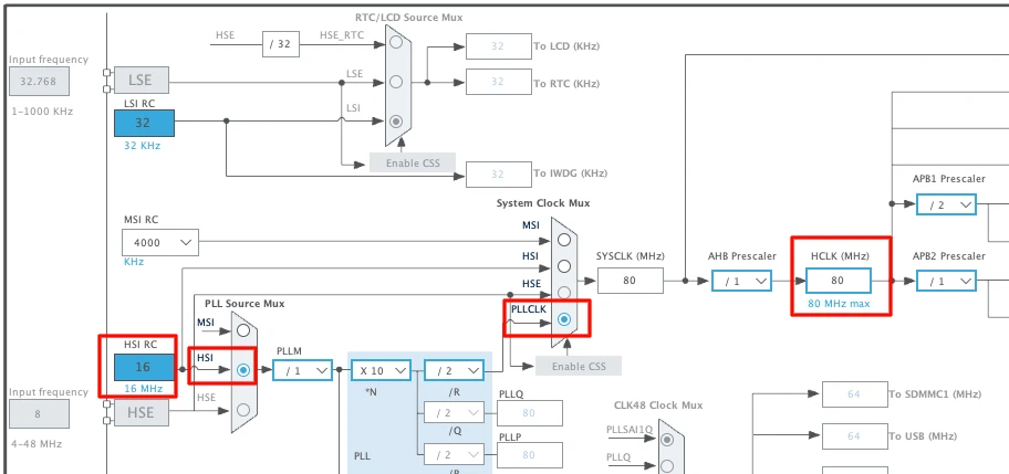
We will use the internal oscillator (HSI) and PLL to run the system at maximum 80MHz clock.
Enable CMSIS-RTOS V2 in Middleware
Now we will enable the CMSIS-RTOS. The configuration can be found in the Middleware section as shown in the image below.
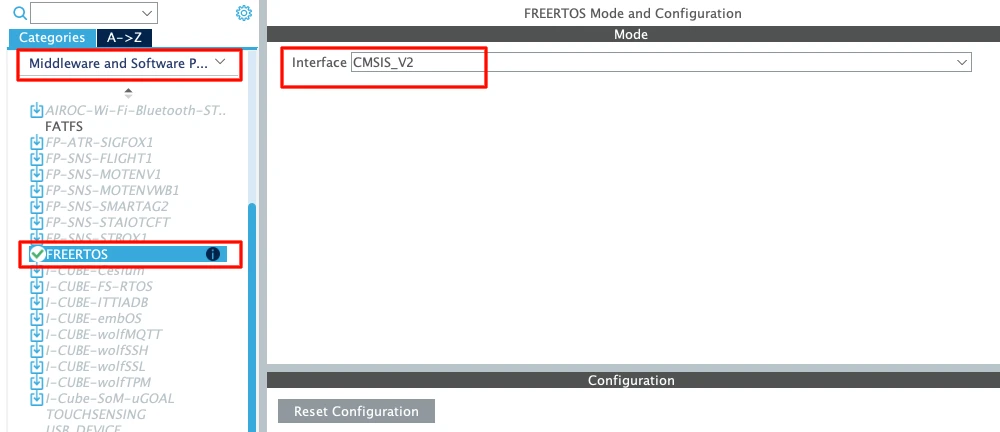
Always choose CMSIS-RTOS V2 for new projects. It is cleaner and more modern.
Let’s understand the basic parameters.
Tick Rate
The default tick rate is 1000 Hz.
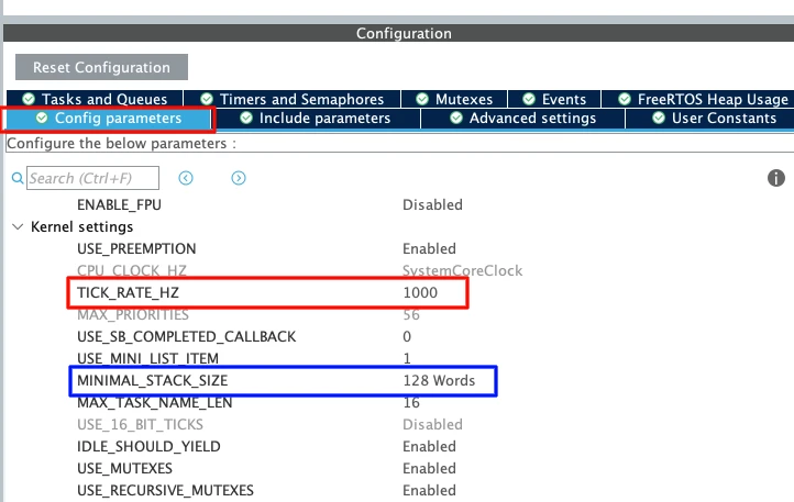
This means the sysTick interrupt runs 1000 times per second which provides 1 ms resolution.
So when we use osDelay(1) It delays approximately 1 millisecond.
Since the maximum tick rate is 1000 Hz, we cannot generate delays smaller than 1 millisecond in FreeRTOS.
Minimal Stack Size
The default value is 128 words.
Note that this is in words, not bytes. Since STM32 is a 32-bit MCU:
1 word = 4 bytes
128 words = 512 bytes
Each task has its own stack. If the stack is too small, the system may crash due to stack overflow. For now, 128 words is enough for a simple LED task.
Total Heap Size
The default heap size is around 3000 bytes.
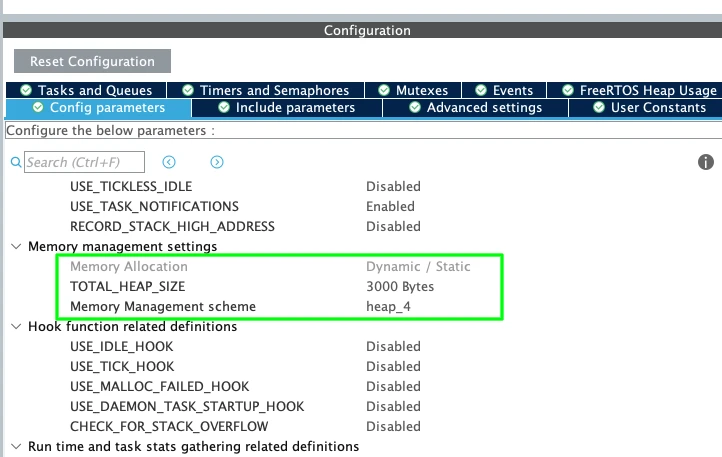
This heap is used for:
- Tasks
- Queues
- Semaphores
- Timers
- Other RTOS objects
When we create a new task, memory is taken from this heap. For this simple example, 3000 bytes is more than enough. Later, when we add more RTOS features, we may need to increase it.
Configuring the DefaultTask
Now go to Tasks and Queues. You will see one task already created: DefaultTask.
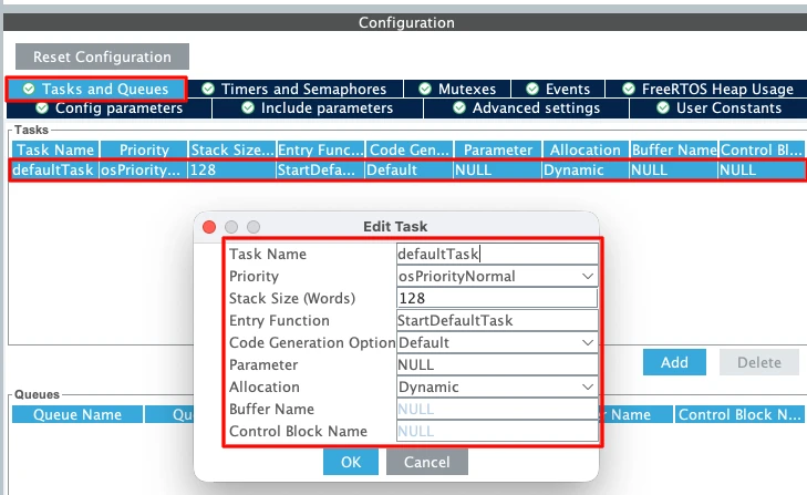
The parameters of this defaultTask are as follows:
- Task Name: DefaultTask
(Only for identification) - Priority: Normal
We will keep it as Normal for now. - Stack Size: 128 words
Minimum allowed value. - Entry Function:
StartDefaultTask
This is where we will write our code later. - Argument: NULL
We are not passing any parameters. - Memory Allocation: Dynamic
The stack and Task Control Block will be allocated from the heap at runtime.
Separate SysTick from HAL — Move Time Base to TIM6
This step is very important in STM32 FreeRTOS projects. By default, STM32 uses SysTick as the HAL time base. But FreeRTOS also uses SysTick for its scheduler.
If both HAL and FreeRTOS share SysTick, it may create timing conflicts.
So we should dedicate:
- SysTick → FreeRTOS Scheduler
- TIM6 (or TIM7) → HAL Time Base
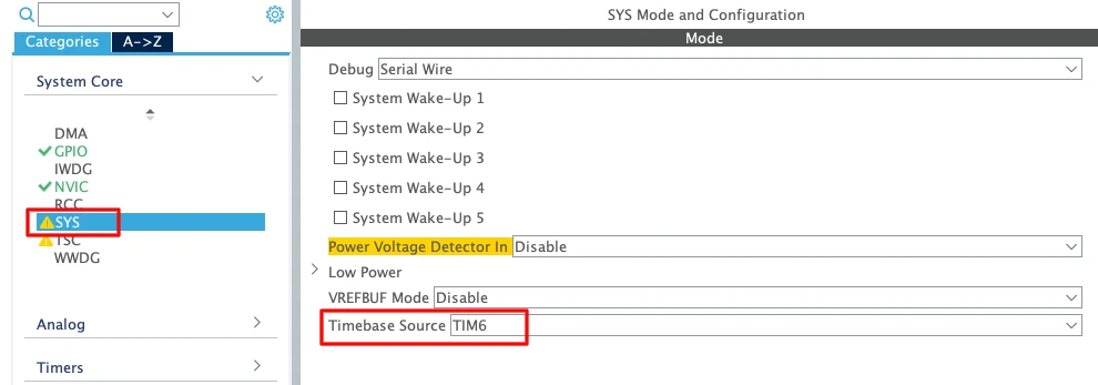
- Go to System Core → SYS
- Change Timebase Source from SysTick to TIM6 (or TIM7)
TIM6 and TIM7 are basic timers. They do not support PWM or advanced features. That is why they are ideal for this purpose.
Enable Newlib Reentrant for Thread Safety
Go to Middleware → FreeRTOS → Advanced Settings and Enable Use newlib reentrant.
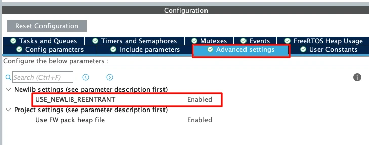
In an RTOS environment, multiple tasks may call functions like printf(); sprintf(); malloc(); etc. These standard C library functions are not thread-safe by default.
If two tasks call printf() at the same time, the output may get corrupted. Enabling newlib reentrant makes these functions safe in multitasking systems. It uses slightly more memory, but it prevents difficult debugging issues later.
Configure GPIO for the LED (PB7)
Now we will configure the onboard LED. According to the board schematic, the blue LED is connected to PB7. Therefore, we will configure the pin PB7 in the output mode.
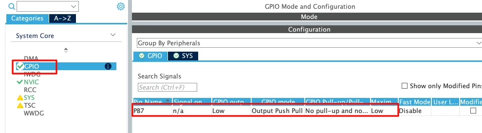
We do not need to change any other GPIO settings for this example. Later inside the task, we will toggle this pin using HAL_GPIO_TogglePin().
FreeRTOS Code Generated by CubeMX — Explained
After generating the project from STM32CubeMX and opening it in STM32CubeIDE, you will see that most of the FreeRTOS-related code is already written for you.
Let’s understand the most important functions that control the RTOS behavior.
osKernelInitialize() — What It Does
This function initializes the FreeRTOS kernel. It prepares all internal RTOS data structures such as:
- Task control blocks
- Ready lists
- Delayed lists
- Memory management structures
It simply prepares the RTOS environment so that tasks can be created safely. You will usually see it inside main() before any task creation.
osThreadNew() — Creating the Task
This function is used to create a new task (thread). CubeMX automatically generates the required parameters like DefaultTask, Entry function (for example StartDefaultTask), Stack size and Priority.
When osThreadNew() is called:
- Memory is allocated from the FreeRTOS heap
- A Task Control Block (TCB) is created
- The task is added to the ready list
Note:
The task function does not start running immediately.It will only run after the scheduler is started.
You can create multiple tasks by calling osThreadNew() multiple times.
osKernelStart() — Starting the Scheduler
This is the most important function. When osKernelStart() is called:
- The FreeRTOS scheduler starts
- SysTick begins generating RTOS ticks
- Context switching becomes active
- The highest priority ready task starts executing
From this moment the system is fully under RTOS control. This function never returns under normal conditions. Therefor, any code written after it in main() will not execute.
If you need continuous execution, you need to put your logic inside a task (Not inside main() after osKernelStart()).
First STM32 FreeRTOS Task — LED Blink
Now that the FreeRTOS project is generated, let’s write our first task. We will blink the onboard LED connected to PB7 on the STM32 Nucleo-L496ZG-P.
Writing the Task Code
We have created only one task, DefaultTask, and the entry function for this task is shown below.
void StartDefaultTask(void *argument);Basically, we need to write our code inside this function.
void StartDefaultTask(void *argument)
{
  for(;;)
  {
    HAL_GPIO_TogglePin(GPIOB, GPIO_PIN_7);
    osDelay(500);
  }
}Below is the explanation of the function:
- The LED toggles every 500 ms
- The task sleeps for 500 ms
- FreeRTOS can run other tasks during that delay
This creates a clean 1-second blink cycle.
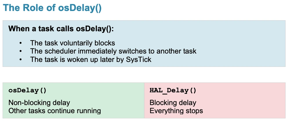
osDelay() vs HAL_Delay() — Critical Difference
In bare-metal projects, we usually write HAL_Delay(1000), but in a FreeRTOS project, we should use osDelay(1000).
This is because HAL_Delay() blocks the CPU. It uses the HAL time base and performs a busy wait. While waiting, no other task can run efficiently.
On the other hand:
osDelay()is RTOS-aware.- It puts the current task into the Blocked state.
- The scheduler switches to another ready task.
- CPU time is used efficiently.
Full main() and Task Code
Below is the simplified structure of main() and the task:
int main(void)
{
HAL_Init();
SystemClock_Config();
MX_GPIO_Init();
MX_FREERTOS_Init();
osKernelInitialize();
osThreadNew(StartDefaultTask, NULL, &defaultTask_attributes);
osKernelStart();
while (1)
{
}
}
void StartDefaultTask(void *argument)
{
  for(;;)
  {
    HAL_GPIO_TogglePin(GPIOB, GPIO_PIN_7);
    osDelay(500);
  }
}Important reminder:
- Code after
osKernelStart()will not run. - All application logic must be inside tasks.
Output — LED Blink at 500 ms
After flashing the project to the board, the LED should blink once every second. The GIF below demonstrates the expected output.
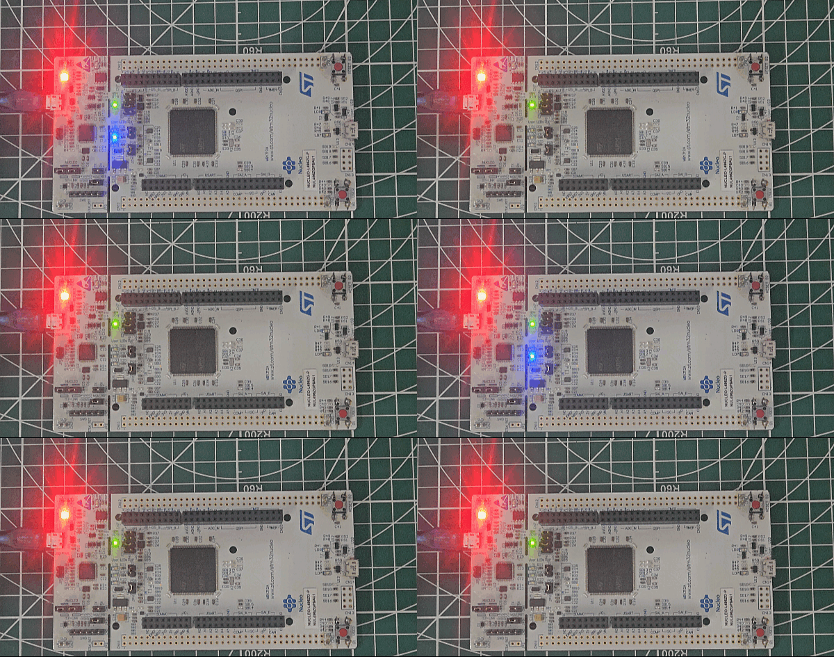
You can see above:
- The LED connected to PB7 will blink every 500 ms.
- The blinking will continue indefinitely.
- The scheduler is now running in the background.
STM32 FreeRTOS — Frequently Asked Questions
Conclusion
This tutorial set up the foundation for every STM32 FreeRTOS project that follows. You saw exactly why HAL_Delay() breaks multi-task firmware — it blocks the CPU entirely — and why the state machine workaround becomes unmanageable as feature count grows. FreeRTOS solves both problems at once: tasks block independently, the scheduler fills those gaps with useful work, and the architecture stays readable.
In CubeMX, you configured CMSIS-RTOS V2 as the middleware layer, set the tick rate, sized the heap and task stack, separated the HAL time base from FreeRTOS's SysTick tick interrupt by moving it to TIM6, enabled newlib reentrant for thread-safe printf() and malloc(), and configured PB7 as the LED output. The generated code — osKernelInitialize(), osThreadNew(), osKernelStart() — follows directly from the CMSIS-RTOS V2 abstraction that maps to xTaskCreate() and vTaskStartScheduler() inside the FreeRTOS kernel.
The LED blink task is intentionally minimal. One task, one osDelay(), one observable output. But this is the exact same pattern that scales to ten tasks running concurrently — each sleeping independently, each resuming exactly on schedule, none blocking the others.
The next step in this series is Part 2 — Multiple Tasks, Priorities & Preemption, where you will create two independent tasks at different priorities and observe how the scheduler decides which runs and when. From there the series moves into Queues for inter-task data exchange and Semaphores for synchronisation. Browse the full STM32 FreeRTOS tutorial series for all parts.
Download STM32 FreeRTOS LED Blink Project Files
Complete STM32CubeIDE project for the STM32 Nucleo-L496ZG-P with CMSIS-RTOS V2 configured: FreeRTOS middleware enabled, HAL time base moved to TIM6, newlib reentrant enabled, PB7 GPIO configured, and DefaultTask LED blink running at 500 ms using osDelay(). Adaptable to any STM32 board with GPIO pin adjustment. Free to download — support the work if it helped you.
Browse More STM32 FreeRTOS Tutorials
STM32 FreeRTOS Queue Tutorial: Inter-Task Communication with CMSIS-OS V2
STM32 FreeRTOS Semaphores: How to Use Binary and Counting Semaphores
STM32 FreeRTOS Mutex: Priority Inheritance & Recursive Mutex
STM32 FreeRTOS Event Flags: osFlagsWaitAll, WaitAny & ISR Callbacks
STM32 FreeRTOS Software Timers: Periodic & One-Shot with CMSIS-OS V2

Subscribe
Login
0 Comments
Newest

