Home ▸ STM32 Tutorials ▸
Updated On: September 14, 2025
External Interrupt using Registers
This is another tutorial in the Register based programming series and today we will see how can we use the external interrupt in STM32. This tutorial will also introduce the working with interrupts in STM32
I am going to focus on F4 and F1 series here. The code will be mainly written for F4 series, but wherever the changes are needed according to the F1 series, I will include them also
Let’s start by configuration first
VIDEO TUTORIAL
You can check the video to see the complete explanation and working of this project.
Configuration
GPIO Configuration
First of all we will start with configuring the GPIO. I have already covered this for the F4 series and the F1 Series in my previous Tutorial, STM32 GPIO INPUT Configuration
Go to the above link, and see the configuration part.
INTERRUPT Configuration
We need to configure the External Interrupt and to do so, the steps are shown below
	/*************>>>>>>> STEPS FOLLOWED <<<<<<<<************

	1. Enable the SYSCFG/AFIO bit in RCC register
	2. Configure the EXTI configuration Register in the SYSCFG/AFIO
	3. Disable the EXTI Mask using Interrupt Mask Register (IMR)
	4. Configure the Rising Edge / Falling Edge Trigger
	5. Set the Interrupt Priority
	6. Enable the interrupt

********************************************************/Let’s cover them one by one
1. Enable the SYSCFG/AFIO Bit
This bit will enable the configuration controller clock. In F4 series, we can do this by enabling the SYSCFG bit in the RCC_APB2ENR Register
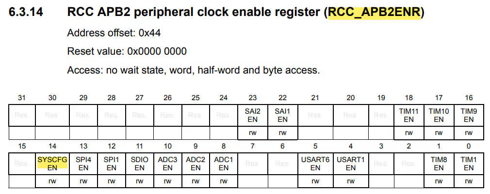
RCC->APB2ENR |= (1<<14); // Enable SYSCNFGIn F1 Series, we need to enable the AFIO bit in the RCC_APB2ENR Register
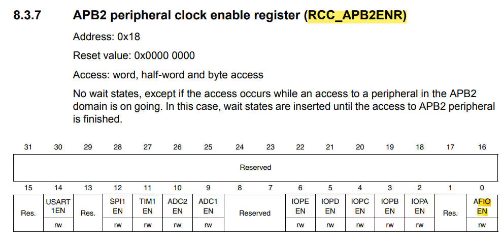
RCC->APB2ENR |= (1<<0); // Enable AFIO CLOCK2. Configure the EXTI configuration Register
In the F4 Series, External Interrupt Configuration can be found in the SYSCFG Registers. These EXTI configuration Registers are divided into 4 groups
- SYSCFG_EXTICR1 (EXTI0 to EXTI3)
- SYSCFG_EXTICR1 (EXTI4 to EXTI7)
- SYSCFG_EXTICR1 (EXTI8 to EXTI11)
- SYSCFG_EXTICR1 (EXTI12 to EXTI15)
Since we are using PA1, we will be using SYSCFG_EXTICR1.
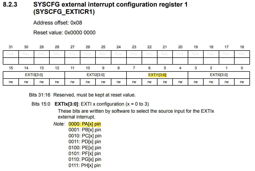
As you can see above, to configure the EXTI line for PA1, we need to modify bits 7:6:5:4 with 0:0:0:0
SYSCFG->EXTICR[0] &= ~(0xf<<4); // Bits[7:6:5:4] = (0:0:0:0) -> configure EXTI1 line for PA1Similarly in F1 series, instead of SYSCFG, we have AFIO Registers. Rest of the logic and the code is identical
AFIO->EXTICR[0] &= ~(0xf<<4); // Bits[7:6:5:4] = (0:0:0:0) -> configure EXTI1 line for PA13. Disable the EXTI Mask
Now onwards the steps will be common for the F4 and F1 series. Here we will disable the mask for the respective pin. This can be done by modifying the Interrupt Mask Register (EXTI_IMR)
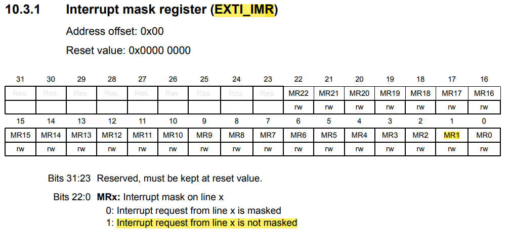
As you can see above, in order to disable the mask from a particular pin, we need to write a ‘1’ in the respective location.
EXTI->IMR |= (1<<1); // Bit[1] = 1 --> Disable the Mask on EXTI 14. Configure the Rising/Falling Edge Trigger
We can configure either we want the interrupt to trigger on the rising edge, or the falling edge of the input signal. These configuration can be controlled in the Rising trigger Selection Register (EXTI_RTSR) and the Falling trigger selection register (EXTI_FTSR).
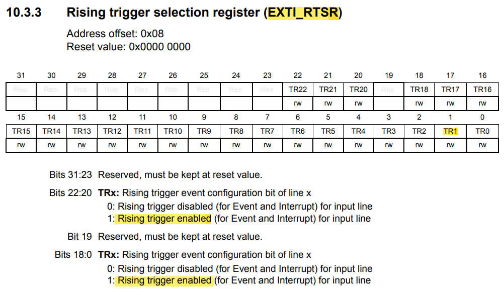
I am selecting the Rising trigger for this tutorial, so I will enable the Rising trigger and Disable the Falling trigger
EXTI->RTSR |= (1<<1);  // Enable Rising Edge Trigger for PA1

EXTI->FTSR &= ~(1<<1); // Disable Falling Edge Trigger for PA15. Set the Interrupt Priority and Enable the Interrupt
Well to do this, we need to use some predefined NVIC functions and you can see them below
NVIC_SetPriority (EXTI1_IRQn, 1);  // Set Priority

NVIC_EnableIRQ (EXTI1_IRQn); // Enable InterruptHere 1 is the priority for the EXTI1 Interrupt. Basically lower the value, highest is the priority. So here I am keeping this priority pretty high.
This completes the configuration for the Interrupt. Now before going to the main code, let’s see the IRQ Handler
IRQ HANDLER
The steps to handle the Interrupt are shown below
	/*************>>>>>>> STEPS FOLLOWED <<<<<<<<************

	1. Check the Pin, which trgerred the Interrupt
	2. Clear the Interrupt Pending Bit

********************************************************/To check and clear the Interrupt Pending bit, we need to see the interrupt pending register (EXTI_PR)
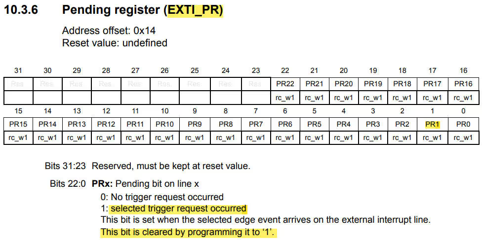
This Pending Register bit is set whenever the interrupt is triggered.
if (EXTI->PR & (1<<1))    // If the PA1 triggered the interrupt
{
        flag = 1;
	EXTI->PR |= (1<<1);  // Clear the interrupt flag by writing a 1
}- Here we will check if the interrupt is triggered by the pin PA1. This can be done by checking the pending bit in EXTI_PR
- Next we will perform the operation and clear the bit by writing a ‘1’ in the respective bit
- Here I am just setting a flag, and the rest of the code will be handled in the main function
The MAIN Function
int main ()
{
	SystemInit();
	GPIO_Config ();
	TIM2_Config();
	Interrupt_Config ();

	while (1)
	{
		if (flag)
		{
			Delay_ms(100);  // avoid debouncing
			count++;
			flag = 0;
		}
	}
}- As you can see above, after initializing everything we will check if the flag is set
- This flag will be set whenever the interrupt is triggered
- Then we will wait for few milliseconds for the debouncing
- Next increment the counter and reset the flag again
STM32 Register based Tutorial Series

STM32F103 Clock Setup using Registers
STM32 GPIO Output Example Using Registers | BSRR, MODER, GPIOA Explained
STM32 GPIO Input Configuration – Pin Setup, Pull-Up, and IDR Read
STM32 I2C Tutorial | Register-Based Configuration with Example Code

STM32 SPI Tutorial Using Registers (Full-Duplex Master with ADXL345)

DMA with ADC using Registers in STM32

How to Setup UART using Registers in STM32


Hello . i could not understand why does EXTI->IMR have to be disable .
Hi, I typed to configurate interruption from PA0 (line0) and set bit[13] once press PA0.
Our code is below, but when i debug and press it nothing happen.
Can you help me find what i errored?
#include “stm32f4xx.h”
void GPIO_configuration(void){
RCC->AHB1ENR |= 8; // enable clock to PD
GPIOD->MODER |= 0x04000000;//MODE OUTPUT pin13 FOR PD
GPIOD->OSPEEDR |= 0x0C000000;//SPEED FOR PD
RCC->AHB1ENR |= 1; // enable clock to PA
GPIOA->MODER |= 0;//MODE INPUT FOR PA
}
void EXTI_Configuarion(void){
/* ************>>>>>>> STEPS FOLLOWED <<<<<<<<************
1. Enable the SYSCFG/AFIO bit in RCC register
2. Configure the EXTI configuration Register in the SYSCFG/AFIO
3. Disable the EXTI Mask using Interrupt Mask Register (IMR)
4. Configure the Rising Edge / Falling Edge Trigger
5. Set the Interrupt Priority
6. Enable the interrupt
*/
RCC->APB2ENR |= (1<<14);
SYSCFG->EXTICR[0] &= ~(0xf);
EXTI->IMR |= 1;
EXTI->RTSR |= (1<<0);
EXTI->FTSR &= ~(1<<0);
NVIC_SetPriority (EXTI0_IRQn, 1);
NVIC_EnableIRQ (EXTI0_IRQn);
}
void EXTI0_IRQHandler(void){
/*************>>>>>>> STEPS FOLLOWED <<<<<<<<************
1. Check the Pin, which triggered the Interrupt
2. Clear the Interrupt Pending Bit
********************************************************/
if (EXTI->PR & 1){// Check the interruption is triggered by PA0
GPIOD->BSRR |= 0x00002000;
EXTI->PR |= 0;
}
}
int main(void)
{
GPIO_configuration();
EXTI_Configuarion();
}
Your code
EXTI->PR |= (1<<1);
clears ALL the pending interrupt flags, it should be
EXTI->PR = (1<<1); to only clear bit 1
You clear the flag by writing a “1” to the appropriate bit, it is a write only register, reading yeilds “1” for all bits so you are reading the register (all ones) then ORing a 1 to bit 1 and writing it back.
Oh! Thanks for information. That’s right.
thank you for your helpful education