Interface 16×2 LCD with STM32 (No I2C) — 4-bit Guide
If you want a clear, practical way to interface a 16×2 LCD with STM32, this guide is for you. Step by step, we connect the display in 4‑bit mode (no I2C), configure CubeMX GPIO and a timer for accurate delays, and then explain the STM32 LCD code so you can reuse it easily. Along the way, you’ll see the exact wiring, learn why timing matters, and understand each function that prints text. As a result, you’ll get a stable, reusable driver you can drop into IoT, robotics, and automation projects. We also include troubleshooting tips, common mistakes to avoid, and simple upgrades like custom characters, so your LCD quickly becomes a reliable on‑board display.
STM32 LCD 16×2 Video Tutorial
Prefer video? Watch the same wiring, CubeMX setup, and code in action.
Watch the Video- What the 16×2 LCD Is and Where It Helps
- STM32 LCD16x2 Project Requirement
- Why Interface LCD 16×2 with STM32 without I2C ?
- STM32 LCD 16×2 Parallel connection Wiring
- STM32CubeMx Configuration for LCD16x2
- STM32 HAL Code for LCD16x2
- STM32 LCD16x2 HAL main function
- Result of LCD16x2 Interfaced with STM32
- PROJECT DOWNLOAD
- FAQs — STM32 LCD 16×2 Without I2C
What the 16×2 LCD Is and Where It Helps
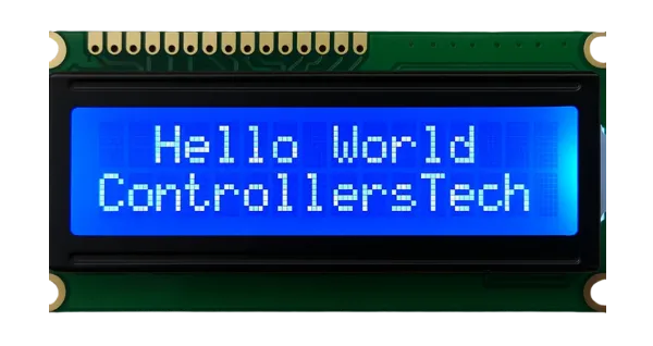
The 16×2 LCD shows 16 characters on two lines. It’s cheap, reliable, and perfect when you just need text: sensor values, menu options, or status messages. Because it uses the classic HD44780 interface, you can run it from an STM32 in either 8‑bit or 4‑bit mode. Here we use 4‑bit mode to save pins without losing features.
LCD16x2 Key features:
- two text lines
- simple commands
- low power
- broad microcontroller support (STM32, Arduino, PIC)
- IoT dashboards
- robot states
- DIY instruments
- quick debugging readouts
STM32 LCD16x2 Project Requirement
I’ve used products mentioned below in this project. I have also added affiliate links for your convenience — if you purchase through these links, it helps support my work at no extra cost to you.
- STM32 development board
- 16×2 LCD module
- 10 kΩ potentiometer for contrast
- Jumper wires and
- Breadboard
Why Interface LCD 16×2 with STM32 without I2C ?
Most tutorials use an I2C adapter with the 16×2 LCD because it saves pins, but connecting the display directly in 4-bit parallel mode has its own advantages:
- Learn the basics → By wiring the LCD directly to GPIO pins, you understand exactly how the controller sends data and commands. This helps beginners grasp how microcontrollers interact with peripherals.
- No extra hardware needed → You don’t need an I2C backpack or converter module like PCF8574. The LCD can work with STM32 out of the box.
- Faster response → Parallel mode can update the display quicker than I2C, which is useful in time-sensitive applications.
- Flexible pin mapping → You can choose which STM32 pins to use, as long as you configure them correctly in CubeMX and code.
- Troubleshooting skills → Working without I2C teaches you how to handle delays, enable/RS lines, and low-level timing issues that are often hidden by higher-level libraries.
Basically we are going to use the parallel connection between STM32, and the LCD itself. LCD 16×2 can be connected in the parallel mode either using 4 data pins (LCD 4 bit MODE) or using all 8 data pins (8 bit MODE). In this tutorial, we are going to use the 4 bit MODE to connect LCD with our microcontroller.
STM32 LCD 16×2 Parallel connection Wiring
We connect the LCD in 4-bit mode, which saves GPIO pins while still giving access to all its features. To keep the display stable, use short jumper wires and make sure the STM32 and LCD share the same ground. Adjust the contrast with a 10 kΩ potentiometer so the characters appear clearly on the screen.
The image below shows the STM32 to LCD 16×2 wiring in 4‑bit mode. This diagram connects RS, RW, EN and data lines D4–D7 to STM32 GPIOs. I have not connected the potentiometer, but instead connected the Vo to 3.3V.
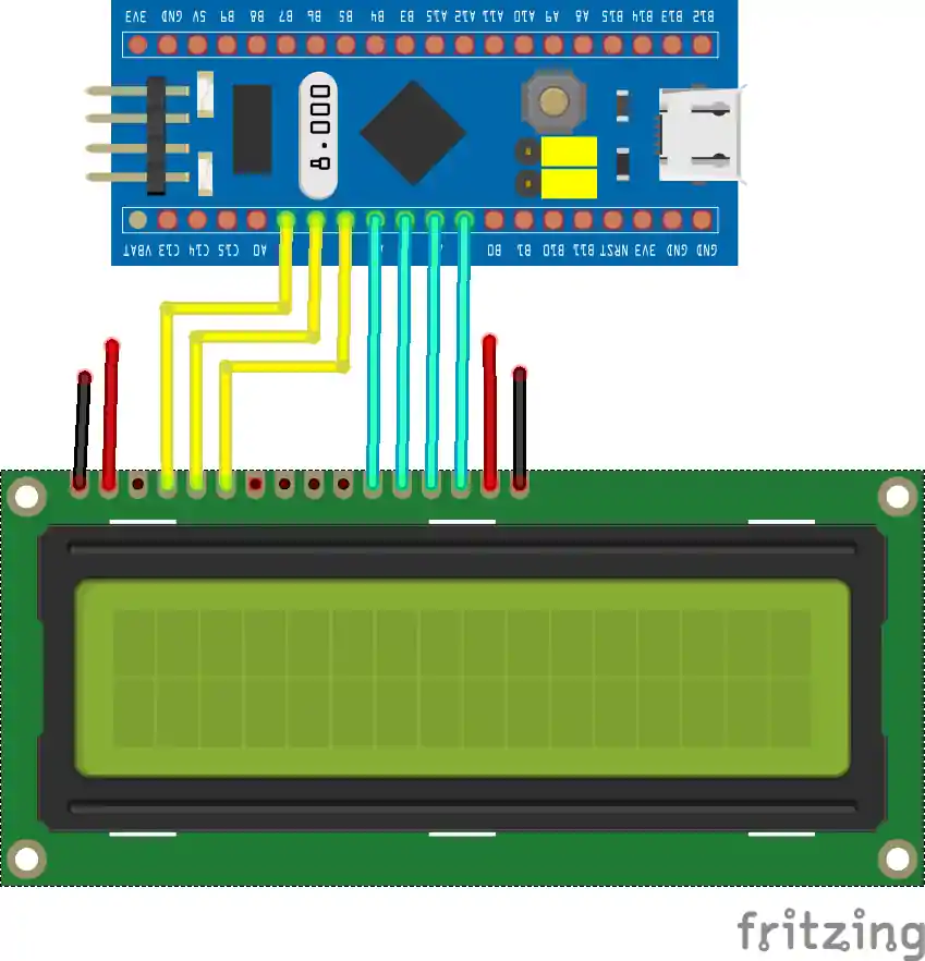
As you can see in the picture above, the higher 4 pins of the LCD ( DB4-DB7) are connected to the microcontroller pins (PA4-PA7). You can connect the pins anywhere you want. It doesn’t have to be in order or in a single port. We will define these pins later in our code.
- RS is connected to PA1
- RW is connected to PA2
- EN is connected to PA3
The display is powered with 5V from the STM32 board itself. The Vo pin of the LCD is connected to 3.3V on the STM32.
STM32CubeMx Configuration for LCD16x2
Here we need to do 2 things. First we will configure the LCD pins as output and then configure the Timer to generate delay in microseconds.
GPIO Configuration in CubeMX
The image below shows the GPIO setup for the LCD pins in STM32CubeMX.
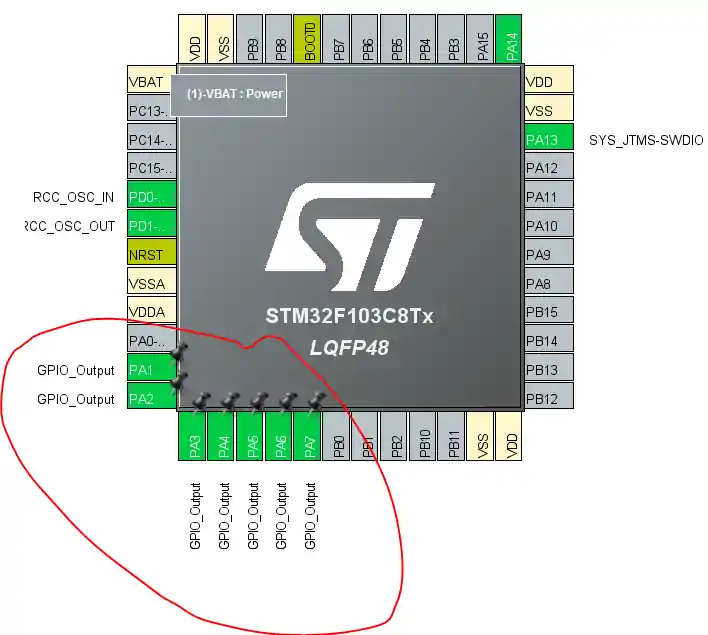
Set RS, RW, EN, and D4–D7 as Output Push‑Pull with high speed. No pull‑ups are required.
Timer Configuration for Microsecond Delay
Now configure the timer to create delay in microseconds. If you are using HCLK less than 100 MHz, you do not need this. I am setting it up just for demonstration. I have already explained How to use Timer to generate delays in microseconds, so if you have any confusion here, just read the tutorial.
The image below shows the timer setup that provides microsecond‑level delays for LCD timing.

Configure the timer prescaler and period to get a 1 µs tick. This is used by the delay function so the LCD receives stable EN pulses and command timings.
Now the Cubemx setup is done, let’s take a look at the functions that we are going to use
STM32 HAL Code for LCD16x2
First of all we need to define the Pins and Ports that we are going to use for the LCD.
LCD16x2 Pin Definition
As I mentioned in the beginning, you can use any port and pins for the connection. Just make sure you define it in this LCD1602.c file, as shown below
#define RS_PORT GPIOA
#define RS_PIN GPIO_PIN_1
#define RW_PORT GPIOA
#define RW_PIN GPIO_PIN_2
#define EN_PORT GPIOA
#define EN_PIN GPIO_PIN_3
#define D4_PORT GPIOA
#define D4_PIN GPIO_PIN_4
#define D5_PORT GPIOA
#define D5_PIN GPIO_PIN_5
#define D6_PORT GPIOA
#define D6_PIN GPIO_PIN_6
#define D7_PORT GPIOA
#define D7_PIN GPIO_PIN_7Microsecond Delay
Now we will write a function to give us the delay in microseconds. You might not need to do this for Lower HCLK. Just replace htim1 with the timer handler that you are using.
#define timer htim1
extern TIM_HandleTypeDef timer;
void delay (uint16_t us)
{
  __HAL_TIM_SET_COUNTER(&timer, 0);
  while (__HAL_TIM_GET_COUNTER(&timer) < us);
}General send_to_lcd() Function
I have created a function to write the data/command to the respective pins of the LCD. This function takes 2 parameters:
- @
datais data/command to be sent to the LCD. - @
rsdecides whether the first parameter is either data (rs=1) or command(rs=0).
void send_to_lcd (char data, int rs)
{
    HAL_GPIO_WritePin(RS_GPIO_Port, RS_Pin, rs);  // rs = 1 for data, rs=0 for command
    /* write the data to the respective pin */
    HAL_GPIO_WritePin(D7_GPIO_Port, D7_Pin, ((data>>3)&0x01));
    HAL_GPIO_WritePin(D6_GPIO_Port, D6_Pin, ((data>>2)&0x01));
    HAL_GPIO_WritePin(D5_GPIO_Port, D5_Pin, ((data>>1)&0x01));
    HAL_GPIO_WritePin(D4_GPIO_Port, D4_Pin, ((data>>0)&0x01));
    /* Toggle EN PIN to send the data
     * if the HCLK > 100 MHz, use the  20 us delay
     * if the LCD still doesn't work, increase the delay to 50, 80 or 100..
     */
    HAL_GPIO_WritePin(EN_GPIO_Port, EN_Pin, 1);
//  delay (20);
    HAL_GPIO_WritePin(EN_GPIO_Port, EN_Pin, 0);
//  delay (20);
}The send_to_lcd function is explained below.
- All we have to do is, take the useful data, which is 4 bit long, and write the first bit to the DB4, second bit to DB5, third to DB6, and fourth to DB7.
- Then we need to perform the enable pin strobe to update this data to the respective pins. Which means that first pull the EN pin HIGH, and then pull it LOW.
- If you are using a controller with HCLK more than 100 MHz, than you need to un-comment that delay line, as shown in the code above.
- This is because We have to wait for the enable pin to settle. If the clock is very high, increase the delay.
Sending Command to the LCD
The function lcd_send_cmd() sends the command to the LCD16x2. The parameter of this function is the command that we want to send.
void lcd_send_cmd (char cmd)
{
    char datatosend;
    /* send upper nibble first */
    datatosend = ((cmd>>4)&0x0f);
    send_to_lcd(datatosend,0);  // RS must be while sending command
    /* send Lower Nibble */
    datatosend = ((cmd)&0x0f);
    send_to_lcd(datatosend, 0);
}This function works as following:
- LCD is connected in the 4 bit mode, where only 4 data pins of the LCD are being used.
- The command that we send should also be 4 bit wide. Therefore we have to first send the higher 4bits, and then lower 4bits. RS pin must be 0, for the command operation.
Sending Data to the LCD
The function lcd_send_data() sends the command to the LCD16x2. The parameter of this function is the data character that we want to send.
void lcd_send_data (char data)
{
    char datatosend;
    /* send higher nibble */
    datatosend = ((data>>4)&0x0f);
    send_to_lcd(datatosend, 1);  // rs =1 for sending data
    /* send Lower nibble */
    datatosend = ((data)&0x0f);
    send_to_lcd(datatosend, 1);
}This function works as following:
- LCD is connected in the 4 bit mode, where only 4 data pins of the LCD are being used.
- The data that we send should also be 4 bit wide. Therefore we have to first send the higher 4bits, and then lower 4bits. RS pin must be 1, for the data operation.
Changing the LCD Row
The function lcd_put_cur() sets the cursor on the LCD
void lcd_put_cur(int row, int col)
{
    switch (row)
    {
        case 0:
            col |= 0x80;
            break;
        case 1:
            col |= 0xC0;
            break;
    }
    lcd_send_cmd (col);
}For a 16×2 LCD:
- Row 0 starts at DDRAM address
0x00→ Command = (0x80 | col) - Row 1 starts at DDRAM address
0x40→ Command = (0x80 | 0x40 | col) → (0xC0 | col)
For Example: lcd_put_cur(1,3) → cursor goes to row 1, column 3 (0xC3).
Initializing the LCD in the 4 bit mode
void lcd_init (void)
{
    // 4 bit initialisation
    HAL_Delay(50);  // wait for >40ms
    lcd_send_cmd (0x30);
    HAL_Delay(5);  // wait for >4.1ms
    lcd_send_cmd (0x30);
    HAL_Delay(1);  // wait for >100us
    lcd_send_cmd (0x30);
    HAL_Delay(10);
    lcd_send_cmd (0x20);  // 4bit mode
    HAL_Delay(10);

  // dislay initialisation
    lcd_send_cmd (0x28); // Function set --> DL=0 (4 bit mode), N = 1 (2 line display) F = 0 (5x8 characters)
    HAL_Delay(1);
    lcd_send_cmd (0x08); //Display on/off control --> D=0,C=0, B=0  ---> display off
    HAL_Delay(1);
    lcd_send_cmd (0x01);  // clear display
    HAL_Delay(1);
    HAL_Delay(1);
    lcd_send_cmd (0x06); //Entry mode set --> I/D = 1 (increment cursor) & S = 0 (no shift)
    HAL_Delay(1);
    lcd_send_cmd (0x0C); //Display on/off control --> D = 1, C and B = 0. (Cursor and blink, last two bits)
}The above code is with reference to the pattern given for the initialization in the datasheet of the device.
Basically the function initializes the LCD in 4-bit mode.
- It starts with delays and
0x30commands to ensure the LCD resets properly, then switches to 4-bit mode with0x20. - Next, it configures the display with
0x28(4-bit, 2-line, 5×8 font). - It turns the display off (
0x08), clears it (0x01), sets entry mode (0x06, auto-increment cursor, no shift), and finally turns the display on without cursor/blink (0x0C).
STM32 LCD16x2 HAL main function
Now we will print some data on the LCD16x2 inside the main function.
Print Strings
We will first see how to print the strings on the display.
// Display Strings
lcd_init ();
lcd_put_cur(0, 0);
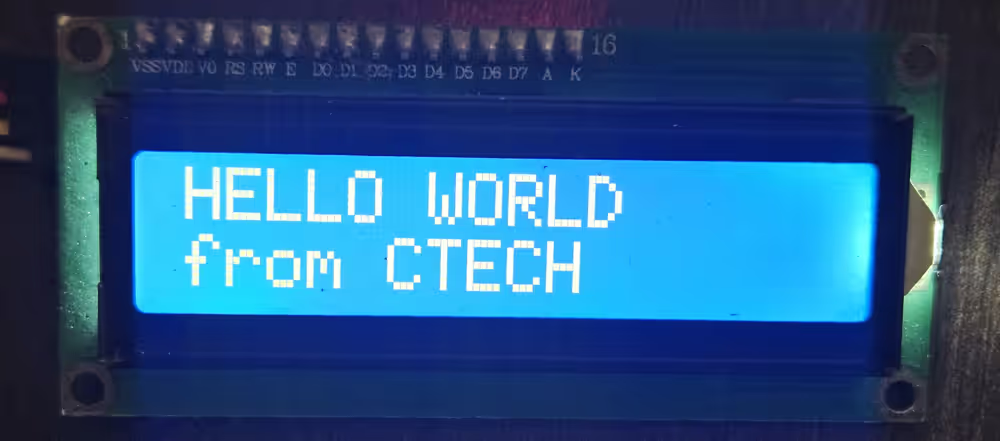
lcd_send_string ("HELLO WORLD");
lcd_put_cur(1, 0);
lcd_send_string("from CTECH");In the main function we will
- Initialise the LCD by calling
lcd_init()function. - Then put the cursor at the beginning of the 1st Row (0,0) and send the string “HELLO WORLD” to this location.
- Then put the cursor at the beginning of the 2nd Row (1,0) and send the string “from CTECH” to this location.
Below is the output of the above code.
Print Number
We can not print the number directly on the display. The display is only capable of printing the Ascii characters by default. Therefore we need to convert the number to the Ascii form and then print it.
Below is the code to convert and print the number.
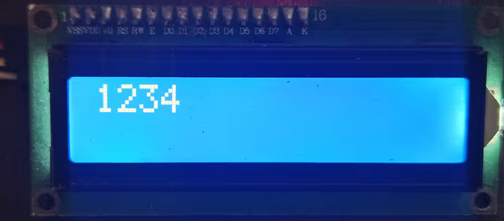
// Display Number
  lcd_init();
  int num = 1234;
  char numChar[5];
  sprintf(numChar, "%d", num);
  lcd_put_cur(0, 0);
lcd_send_string (numChar);In the main function we will
- Initialise the LCD by calling
lcd_init()function. - Let’s say we want to print the number 1234. It has 4 digits, so define a character buffer to store 1 extra byte, i.e 5 bytes.
- Now we will use sprintf to convert the number to the character for and store it in the array we just defined.
- The format specifier, %d, is used to convert integer values to character form.
- Then put the cursor at the beginning of the 1st Row (0,0) and send the array.
Below is the output of the above code.
Print Floats
Just like numbers, we can not print the floats directly on the display. Therefore we need to convert the float value to the Ascii form and then print it.
Below is the code to convert and print the float.
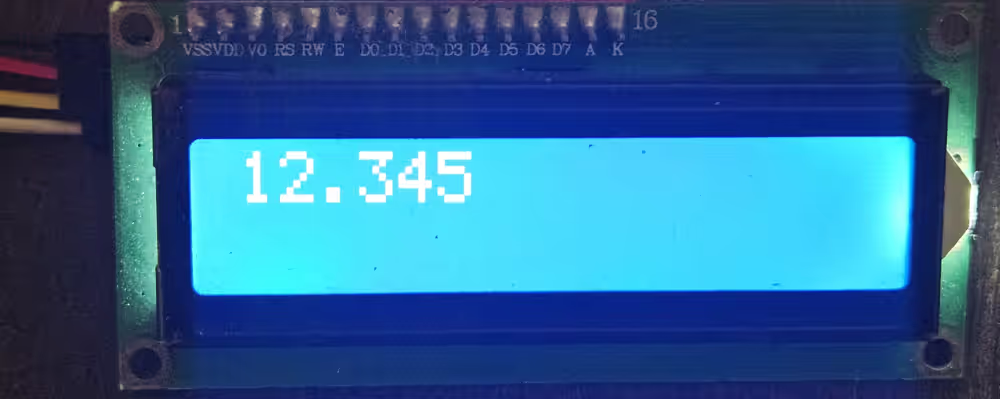
// Display Float
  lcd_init();
  float flt = 12.345;
  char fltChar[7];
  sprintf(fltChar, "%.3f", flt);
  lcd_put_cur(0, 0);
lcd_send_string (fltChar);In the main function we will
- Initialise the LCD by calling
lcd_init()function. - Let’s say we want to print the number 12.345. It has 6 digits, so define a character buffer to store 1 extra byte, i.e 7 bytes.
- Now we will use sprintf to convert the float to the character for and store it in the array we just defined.
- The format specifier, %.3f, is used to convert float values to character form till 3 decimal places.
- Then put the cursor at the beginning of the 1st Row (0,0) and send the array.
Below is the output of the above code.
Result of LCD16x2 Interfaced with STM32
After flashing the firmware and powering the board, the LCD should initialize and print the message. If it does not, verify power, contrast, and that the EN pulse width and command delays match the LCD datasheet.
In this wiring, we use 4‑bit mode to save GPIOs while keeping full LCD features. Keep wires short, share ground between STM32 and LCD, and set the contrast with a 10 kΩ potentiometer so the characters are visible.
The image below shows the LCD output after uploading the code.
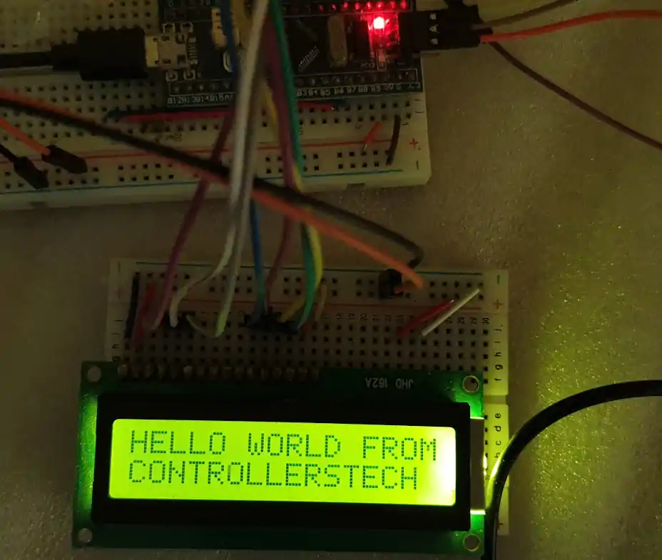
Seeing the text confirms correct wiring and initialization. If you only see blocks, adjust the contrast, recheck RS/EN wiring, and ensure the init sequence runs before printing.
Now you’ve seen how to interface a 16×2 LCD with STM32 without I2C: proper CubeMX pins and timer, tidy 4-bit wiring, and straightforward driver functions. With reliable microsecond delays and simple APIs, you can print text anywhere in your firmware. Next, try custom characters, scrolling text, and small menus to build a handy on-board UI. Finally, keep wires short and timings tight—those two habits make your STM32 LCD projects stable and repeatable. If you’d like to simplify the wiring even more, check out how to use a 16×2 LCD with STM32 over I2C.
PROJECT DOWNLOAD
FAQs — STM32 LCD 16×2 Without I2C


Hi, I hope you’re well. I walked through your tutorial, and I can only get the cursor to blink with no data. I was wondering if I could have your help?
Thanks
please, why I can’t load the the download website
Hello, thank you very much, Sir.
Would you mind, can I translate your tutorial to Thai language?
I guess google translate does the job good enough. But anyway if you want you can do it. Make sure to give credits though.
Hi,
When I tried this with my stm32 and the maximum clock is 32MHz, it is showing weird character. It seems I have problems with the LCD initialize. I tried with the board that can be set to 72MHz, the LCD works like a charm.
Do I need to adjust the delay?
Check the microsecond delay part. You need to change setting for it (delay) to work properly.
Thank you for the help. If I understand correctly that you said with HCLK below 100MHz, then we don’t need to use microsecond delay?
But I did set the timer as your setting but just change the PSC = 32-1 instead of 72-1 and the rest is the same as yours. Is there any factor leading to this problem?
contact me on telegram or discord. I need to see the code first
Hello, I’m using STM32G030K6T6, its maximum clock is 64MHz and I’m facing the same problem, could you help me?
just give some delay inside the send command and send data functions.
You can also use something like
uint32_t del = 10000;
while (del–);
hey, you managed to fix it? my clock can’t exceed 32MHz too and I cant find the right delay to make it work well
Hi, I’d like to ask, what are those logic ands with 0x0f in sending commands for?
My code run on STM32F100RB With
void LCDInit(void)
{
//4 bit initialisation
//display initialisation
HAL_Delay(500);
LCDSendCommand(0x02); // Return Home
LCDSendCommand(0x28); //4 bit mode
LCDSendCommand(0x0C); //Display on/cursor off
LCDSendCommand(0x01); // clear display
HAL_Delay(100);
}
rest is same
now lets enjoy the coffee
i am using 16*4 display, can i use this code for my implementaion, what are all things i have to do? please anyone answer me
Can you make the tutorial with the f303k8 as well? I followed the same tutorial but had some errors in the end saying failed to start GDB server, other errors were: Target Held under Reset
Error in initializing ST-LINK device.
Reason: Target held under reset.
“I folowed the tutorial” ? Well your error have nothing to do with tutorial. This is specific to your board.
I would suggest that run saome basic things first, and then go higher.
“Can you make the tutorial with the f303k8 as well”. Well send me the board, and I will make it.
ST have hundreds of boards, and I can’t make for all of them. That’s why I show the process, instead of just uploading the code
hi bro, can i go for 16*4 display,could i take this code for my implementation?
hey admin , i have a nucleo board G474 and i burn the program and i try to change the delay , and still not work , can you help me please?
Surely Coffee my friend
hi, how do i use variables inside the print function?
first change the variable value
then convert it to the characters using the sprintf function
then print on the display
Hello, for me everything fine, the debuging is completed, but the lcd doesn’t work.
the stm program go directly to the sentence : HAL_Init();
can u maybe help me?
Thanks
I have the same problem, probably u dont put the V0 pin (LCD) to GND, is not in the diagram, but u have to put it
Hi, The lcd shows a blank screen.
hi, where is the function lcd_send_string described?
It’s in the LCD1602.c file
Hmm! I’m wondering if the 1602A is different from the one mentioned in this tutorial. While going over the init from Arduino I noticed the RS and E pins were set to 12 and 11, and I don’t see those in the init code here. Meh, I’ll have to go through it all thoroughly and then disassemble the arduino code.
My mistake. Still going through the code, though. As it’s still not running on this.
All the pins are declared in LCD1602.c file. This information is mentioned in this article also.
I know. Should have mentioned I was attempting to translate from a cpp library file that is called from a c file so kind of got confused.
Anyway, other than removing some redundant code and renaming/re-assigning the routines and pins from the sources here, the only thing that is really different is I don’t quite understand how to handle the timers as of yet (if needed for this example on my stm32l152c board). So I used HAL_Delay (which I’ve read isn’t the best choice), uwTick, and for loops.
Well, once I can get around to it. I’ll go through everything again and see what happens. Might even hook it up to the arduino and use the example code with it just to be sure the device works.
I’m still learning.
<Edit> AHA! I forgot to ground RW. That was the problem.
ground RW?
What does mean?
connect the R/W pin to ground
Really I have not seen you like your usual .. it is a very good professional explanation … Thanks for the effort you made
LCD.c(30): warning: #188-D: enumerated type mixed with another type
HAL_GPIO_WritePin(RS_GPIO_Port, RS_Pin, rs); // rs = 1 for data, rs=0 for command
LCD.c(33): warning: #188-D: enumerated type mixed with another type
HAL_GPIO_WritePin(D7_GPIO_Port, D7_Pin, ((data>>3)&0x01));
LCD.c(34): warning: #188-D: enumerated type mixed with another type
HAL_GPIO_WritePin(D6_GPIO_Port, D6_Pin, ((data>>2)&0x01));
LCD.c(35): warning: #188-D: enumerated type mixed with another type
HAL_GPIO_WritePin(D5_GPIO_Port, D5_Pin, ((data>>1)&0x01));
LCD.c(36): warning: #188-D: enumerated type mixed with another type
HAL_GPIO_WritePin(D4_GPIO_Port, D4_Pin, ((data>>0)&0x01));
LCD.c(42): warning: #188-D: enumerated type mixed with another type
HAL_GPIO_WritePin(EN_GPIO_Port, EN_Pin, 1);
LCD.c(44): warning: #188-D: enumerated type mixed with another type
HAL_GPIO_WritePin(EN_GPIO_Port, EN_Pin, 0);
HOW TO FIX IT ???
Yeah i have the same problem and i try to run program, I have hardfault interrupt.
You can’t run into hardfault with those warnings. They are there because I have used ‘1’ instead of GPIO_STATE_SET, and ‘0’ instead of GPIO_STATE_RESET. That’s completely fine.
Debug you code step by step and check what’s causing the hardfault and report
/* Check whether or not the timer instance supports internal trigger input */
assert_param(IS_TIM_CLOCKSOURCE_ITRX_INSTANCE(htim->Instance));
TIM_ITRx_SetConfig(htim->Instance, sClockSourceConfig->ClockSource);
break;
}
after here (this was from stm32f1xx_hal_tim.c (also disassembly table 4606 column)) itgoes into hardfault interrupt w1_hardfault_ırqn 0 .
Also my lcd just glow i tried to change delay but no change.
Can u post pictures of the clock setup and timer setup.
Better join the telegram group (link on the top right). You will get better 1-1 support there
I have programmed the same to my STM32F103 Nucleo Board. Everything is fine. However, no character is being displayed at the LCD. It just glow, but nothing to display.
try changing the delay..
Awesome post! Keep up the great work! 🙂
hello admin……
thank you for your information…….
can you please explain the audio player using sd card
thank you
Hello ! I have already repeated your interface lcd 1602 project without I2C. Everything works great. Now I will add ds18b20 to it. Thank you very much.
please send the code
Good afternoon!
I’m very interested in polling buttons in projects. Eliminating chatter of contacts. Do you have an example with button processing?