
Home ▸ STM32 Tutorials ▸ Modbus ▸
Updated On: May 9, 2026
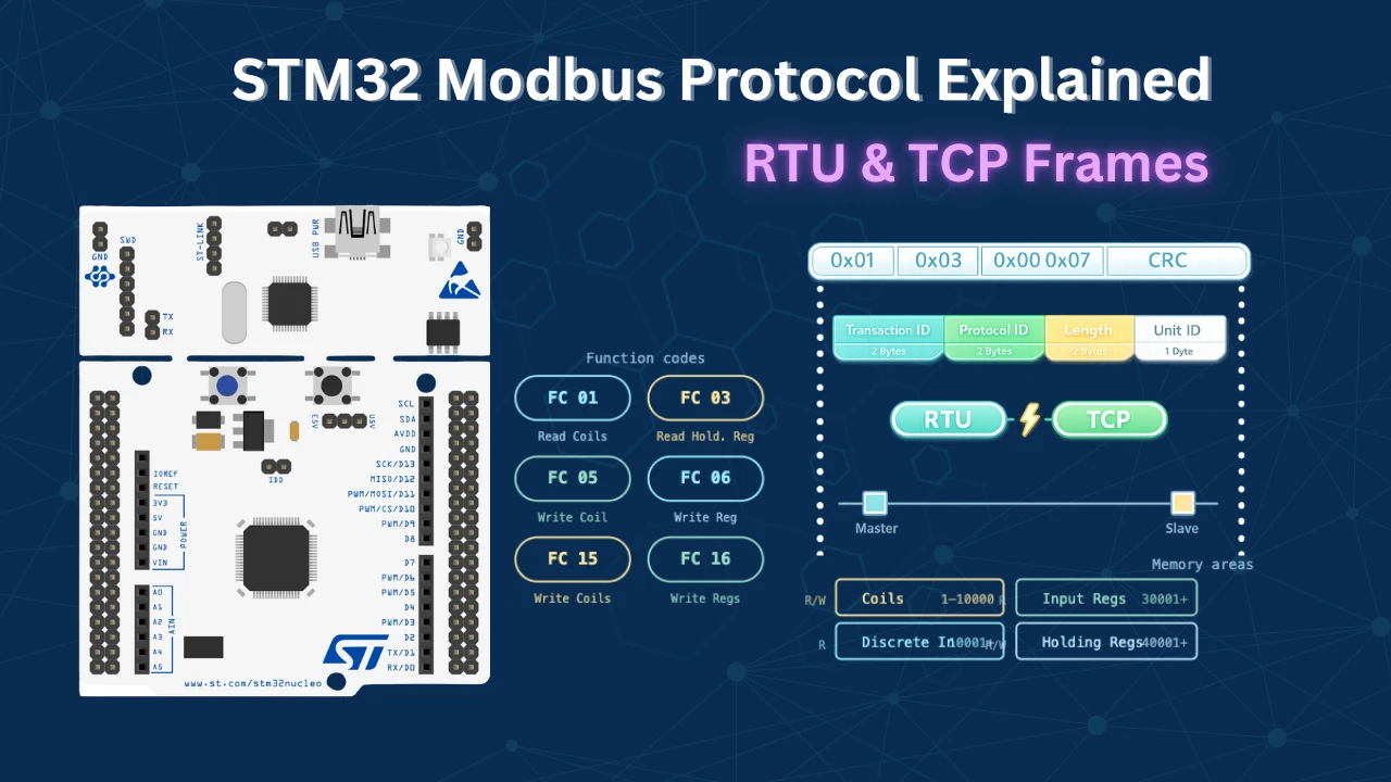
Modbus Protocol Explained: RTU & TCP — Frame Structure, Function Codes, and Memory Map
Most embedded engineers encounter Modbus on the factory floor — a PLC needs to talk to a sensor over RS-485, or an STM32 needs to serve register data to a SCADA system over Ethernet. Modbus is the protocol that makes all of that work. It is decades old, deliberately simple, and still one of the most widely deployed industrial communication protocols in the world.
This guide covers everything you need to understand before writing a single line of Modbus code. We start with the data model — how Modbus organises memory into coils and registers — then walk through the RTU frame structure and function codes. From there, we move into Modbus TCP: how the same core logic maps onto an Ethernet network, and how the MBAP header replaces the RTU address and CRC.
If you are building Modbus into an STM32 project, this is the foundation article for both series: the Modbus RTU series (RS-485, master and slave, all function codes) and the Modbus TCP series (Ethernet-based Modbus server and client using STM32 HAL).
How Modbus Works: Data Model & Memory Areas
Before looking at any frame bytes, you need to understand how a Modbus device organises its data. Every Modbus device — whether it is a PLC, a sensor, or an STM32 — exposes a set of memory areas that a master (or client) can read from and write to.
The Four Memory Areas
Modbus defines four distinct types of memory, each occupying a different address range:
| Memory Type | Address Range | Size | Access |
|---|---|---|---|
| Coils | 00001 – 09999 | 1 bit each | Read / Write |
| Discrete Inputs | 10001 – 19999 | 1 bit each | Read only |
| Input Registers | 30001 – 39999 | 16 bits each | Read only |
| Holding Registers | 40001 – 49999 | 16 bits each | Read / Write |
Coils are single-bit, read/write memory locations. Think of them as digital outputs — an ON/OFF flag that the master can set.
Discrete Inputs are also single-bit, but read-only. They represent the state of digital inputs on the slave device — things a master can monitor but not control.
Input Registers are 16-bit read-only registers. These typically hold real-time measurement values from sensors — temperature, pressure, ADC readings, and so on.
Holding Registers are 16-bit read/write registers. This is the most commonly used memory area. The master can both read and write here — useful for configuration values, setpoints, and control parameters.
The Address Offset System
Here is something that trips up a lot of users. When the master wants to read a holding register at address 40008, it does not send 40008 in the frame. Instead, it sends the offset.
The offset is calculated as: Actual address − Starting address of that memory area.
For holding registers, the starting address is 40001. So to read register 40008, the master sends: 40008 − 40001 = 7.
But how does the slave know whether the master wants register 00008, 10008, 30008, or 40008 — all of which would also send the value 7? That is where the function code comes in. The master sends Function Code 3 (Read Holding Registers) alongside address 7, and the slave immediately knows: holding registers start at 40001, plus offset 7 = register 40008.
Modbus RTU — Frame Structure & Function Codes
Modbus RTU is the serial variant. It runs over UART, typically on an RS-485 bus. The name RTU stands for Remote Terminal Unit.
The RTU Frame Format
Every Modbus RTU message — whether from master to slave or slave to master — fits the same top-level structure. The maximum frame size is 256 bytes:

| Field | Size | Description |
|---|---|---|
| Slave ID | 1 byte | Address of the target slave device |
| Function Code | 1 byte | What operation the master is requesting |
| Data | Up to 252 bytes | Varies depending on the operation |
| CRC | 2 bytes | Error check (Cyclic Redundancy Check) |
The first three fields — Slave ID, Function Code, and CRC — are always present regardless of the direction or type of message. Only the Data field changes.
Modbus RTU Function Codes
The function code tells the slave what the master wants to do. Different codes handle reading versus writing, and coils versus registers:
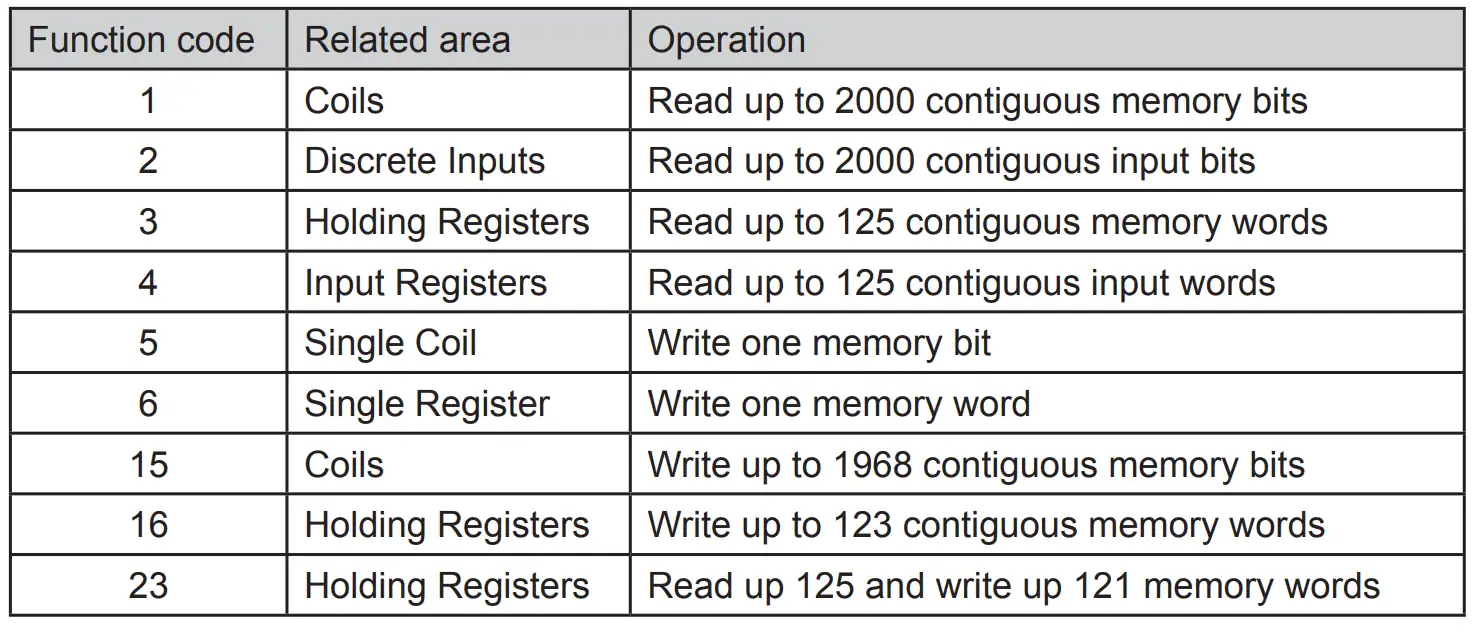
| Function Code | Operation |
|---|---|
| 01 | Read Coil Status |
| 02 | Read Discrete Inputs |
| 03 | Read Holding Registers |
| 04 | Read Input Registers |
| 05 | Write Single Coil |
| 06 | Write Single Holding Register |
| 15 | Write Multiple Coils |
| 16 | Write Multiple Holding Registers |
The RTU Data Field — Three Scenarios
The data field is where everything gets specific. Its contents change depending on what the master is doing.
Scenario 1 — Master Sending a Read Query
When the master wants to read data from the slave, its data field contains two pieces of information:
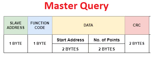
- Start address (2 bytes) — the offset address of the first register or coil to read
- Number of points (2 bytes) — how many coils or registers to read from that address forward
“Number of points” means the number of individual memory units — coils in the case of coils, registers in the case of registers.
Scenario 2 — Slave Responding to a Read Query
When the slave responds, the frame keeps the same Slave ID and Function Code, but the data field changes to:
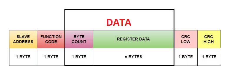
- Byte count (1 byte) — how many data bytes follow
- Data (N bytes) — the actual register or coil values
Scenario 3 — Master Sending a Write Request
When the master wants to write data to the slave, the data field expands to:
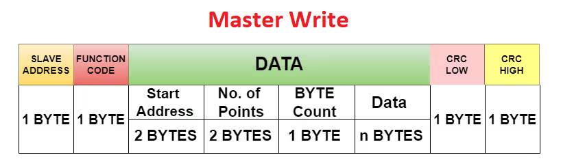
- Start address (2 bytes) — where to start writing
- Number of points (2 bytes) — how many coils or registers to write
- Byte count (1 byte) — how many data bytes follow
- Data (N bytes) — the values to write
A Note on Points vs Bytes
Because coils are 1-bit and registers are 16-bit, the same “number of points” translates to very different byte counts:
- 8 coil points = 8 bits = 1 byte
- 8 register points = 8 × 16 bits = 16 bytes
This is why the protocol uses “number of points” instead of “number of bytes” — it stays consistent regardless of memory type.
Modbus TCP — MBAP Header, ADU, and Frame Structure
Modbus TCP carries the same Modbus data model over an Ethernet network using the TCP/IP protocol. The function codes and register structure are completely unchanged. What changes is the framing around them.
Modbus RTU vs Modbus TCP — What Changed?
The side-by-side comparison makes the difference clear:
Modbus RTU frame:

Modbus TCP frame:

Two things changed and nothing else:
- The Slave ID address byte is replaced by the 7-byte MBAP header.
- The CRC checksum is gone. TCP handles error detection at the transport layer, so no CRC calculation is required.
Everything in the middle — the function code and data bytes — is identical to RTU.
The ADU: Application Data Unit
Every Modbus TCP message is packaged as an Application Data Unit (ADU). The ADU has two sections:

- MBAP Header — metadata about the transaction (7 bytes)
- PDU (Protocol Data Unit) — the function code and data (same as RTU)
The PDU itself is simple:

- 1 byte — Function Code
- N bytes — Data (identical structure to Modbus RTU)
The MBAP Header — Field by Field
MBAP stands for Modbus Application Protocol. The header is 7 bytes and all fields are encoded in Big Endian format (most significant byte first).

Transaction Identifier (2 bytes) The client generates a unique ID for each request. The server copies this value unchanged into its response, allowing the client to match each response back to the correct request — especially useful when multiple requests are in flight simultaneously.
Protocol Identifier (2 bytes) Always 0x0000 for standard Modbus TCP. Both client and server use this value as-is. It exists to allow future protocol extensions but is always zero in practice.
Length Field (2 bytes) Tells the receiver how many bytes follow after this field — specifically, the Unit Identifier byte plus all PDU bytes. The client calculates this based on the request it is sending. The server independently recalculates it based on its response. This field is not copied from the request.
Unit Identifier (1 byte) Equivalent to the Slave ID in Modbus RTU. It is most important when a Modbus TCP gateway bridges multiple serial RTU slaves onto the network — each slave gets a different Unit Identifier. When connecting directly to a single server, its value does not matter. The server copies this field unchanged into its response.
Complete Frame Example: Reading 4 Coils over Modbus TCP
Let us build a real Modbus TCP frame from scratch. The goal: read the status of 4 coils starting at address 0.
Building the Request Frame
| Field | Value | Bytes | Notes |
|---|---|---|---|
| Transaction Identifier | 1 | 0x00 0x01 | First transaction, Big Endian |
| Protocol Identifier | 0 | 0x00 0x00 | Always zero |
| Length | 6 | 0x00 0x06 | Unit ID + FC + Addr + Count = 6 bytes |
| Unit Identifier | 10 | 0x0A | Slave ID = 10 |
| Function Code | 1 | 0x01 | Read Coil Status |
| Starting Address | 0 | 0x00 0x00 | First coil, offset = 0 |
| Number of Coils | 4 | 0x00 0x04 | Read 4 coils |
The complete request frame:

0x00 0x01 | 0x00 0x00 | 0x00 0x06 | 0x0A | 0x01 | 0x00 0x00 | 0x00 0x04Understanding the Server Response
The server receives this frame, processes it, and sends back a response using the same ADU structure. The Length field is recalculated because the response data is different:
| Field | Size |
|---|---|
| Unit Identifier | 1 byte |
| Function Code | 1 byte |
| Byte Count | 1 byte |
| Coil Data | 1 byte |
| Total | 4 bytes |
The complete response frame:

0x00 0x01 | 0x00 0x00 | 0x00 0x04 | 0x0A | 0x01 | 0x01 | 0x000x00 0x04— Length field recalculated by server (4 bytes follow)0x01— Byte Count: 1 byte of coil data follows0x00— Coil data: all 4 coils are OFF (each bit = one coil status)
Verifying with Simply Modbus TCP Client
The Simply Modbus TCP Client tool makes it easy to validate this in practice. Configure it as follows:

- Mode: TCP
- Port: 502 — the standard Modbus TCP port; all servers must listen here
- Slave ID: 10
- Function Code: 1 (Read Coils)
- First Coil Address: 10001 — the offset maps this to register 0 on the server
- Number of Coils: 4
The raw bytes sent and received match exactly the frame we constructed above:
Request generated by the client:

Response received from the STM32 server:

Coil status display after response:

All four coils show 0 (OFF), matching the 0x00 data byte in the response.
Modbus TCP Protocol Explained – Frequently Asked Questions
Conclusion
Modbus is built around a simple idea: a master device requests data from a numbered address on a slave, using a function code to specify the type of operation. Everything else — RTU framing, TCP framing, CRC, MBAP headers — exists to make that basic request-response pattern reliable over different physical transports.
The core model is the same in both RTU and TCP: four memory areas (coils, discrete inputs, input registers, holding registers), a set of function codes for reading and writing each one, and a data field whose structure varies by operation. Master the data model once and you understand both protocol variants.
In Modbus RTU, the frame adds a Slave ID byte and a 2-byte CRC to each message. In Modbus TCP, those are replaced by the 7-byte MBAP header — Transaction ID, Protocol ID, Length, and Unit Identifier — while the CRC is dropped entirely because TCP handles error detection itself. All MBAP fields are Big Endian, and every Modbus TCP server must listen on port 502.
From here, the two series take you from theory into working embedded code. The Modbus RTU series covers STM32 as both master and slave over RS-485, working through all function codes with real CubeMX projects. The Modbus TCP series takes the same function codes onto Ethernet, implementing a Modbus TCP server and client on STM32 using HAL.
Browse More STM32 Modbus TCP Tutorials


thanks for educations
i have a question
can you teach ascii modbus too???