
Home ▸ STM32 Tutorials ▸
Modbus #7. STM32 as Slave || Writing Coils
This is the 7th Tutorial in the Modbus Series, and we will continue to use the STM32 as a slave Device. This tutorial will cover how the STM32 as a slave device will send a response to the queries regarding writing a single and multiple Coils.
We will cover the function codes FC05 and FC15 in this tutorial, but from the slave prospective.
I have already covered the connection parameters in the previous tutorial, and we will continue with the same connection. In fact this is going to be the same project with a few additions in the modbusslave.c file.
I have just added the functions for writing single Coil and multiple Coils in the modbusslave.c file. The rest of the project is pretty much the same as the previous one.
VIDEO TUTORIAL
You can check the video to see the complete explanation and working of this project.
The Master Sotware
I am using the simply modbus master software, which can be downloaded from https://www.simplymodbus.ca/download.htm
So far we have used the master software for reading the Registers and coils from the slave device. Now we will use it for writing them.
In order to write the data into the slave device, we have to first open the “write” window in the software as shown below

Here inside the RED box if we click the write button, a new window will open. This is shown below
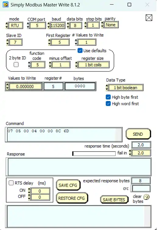
You might be already familiar with all the options shown in this window. We will see the use of the software later in the results section of this tutorial.
Some insight into the CODE
This is the same project in continuation, so I will only explain the parts that have been added in this particular tutorial.
Writing single coil
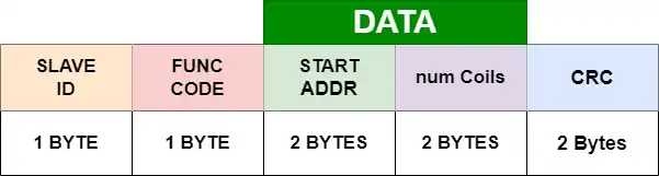
The query format for writing a single coil is shown below.
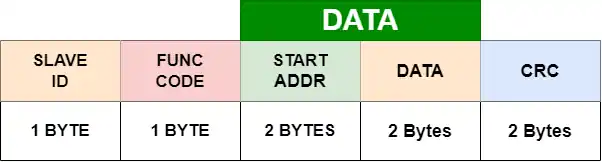
Basically the master sends the coil address followed by the 2 bytes of data. The data sent by the master decides whether to turn the coil ON or OFF.
- If the 2 bytes are (FF 00) hex, the coil will turn ON.
- And If the 2 bytes are (00 00) hex, the coil will turn OFF.
- Any other value does not affect the state of the coil.
uint8_t writeSingleCoil (void)
{
	uint16_t startAddr = ((RxData[2]<<8)|RxData[3]);  // start Coil Address

	if (startAddr>199)  // The Coil Address can not be more than 199 as we only have record of 200 Coils in total
	{
		modbusException(ILLEGAL_DATA_ADDRESS);   // send an exception
		return 0;
	}

	/* Calculation for the bit in the database, where the modification will be done */
	int startByte = startAddr/8;  // which byte we have to start writing the data into
uint16_t bitPosition = startAddr%8; // The shift position in the first byte- Here first we calculate the address of the coil by using the RxData[2] and [3].
- Since I have defined the database for only 200 coils (0-199), if this coil address exceeds 199th coil, the slave will send an exception regarding ILLEGAL_DATA_ADDRESS.
- Then we will calculate the startbyte, the byte in database where the modification will be done, the bitposition, which is the shift in the startByte.
For eg– If the coil address is 15, the startByte = 14/8 = 1 and bitposition = 14%8 = 6. So here we are going to modify the 6th bit in the 1st Byte of the database.
	/* The next 2 bytes in the RxData determines the state of the coil
	 * A value of FF 00 hex requests the coil to be ON.
	 * A value of 00 00 requests it to be OFF.
	 * All other values are illegal and will not affect the coil.
	 */

	if ((RxData[4] == 0xFF) && (RxData[5] == 0x00))
	{
		Coils_Database[startByte] |= 1<<bitPosition; // Replace that bit with 1
	}

	else if ((RxData[4] == 0x00) && (RxData[5] == 0x00))
	{
		Coils_Database[startByte] &= ~(1<<bitPosition); // Replace that bit with 0
}- Then we check for the next 2 Bytes of the RxData buffer, the bytes [4] and [5].
- If the Bytes are FF and 00, the coil must be turned ON, and therefore we will write a 1 in the bitposition.
- similarly, If the Bytes are 00 and 00, the coil must be turned OFF, and therefore we will write a 0 in the bitposition.
We will not write anymore conditions because any other data here does not affect the state of the coil.
Next the slave will send a response to the master. The response format is shown below
	// Prepare Response

	//| SLAVE_ID | FUNCTION_CODE | Start Addr | Data     | CRC     |
	//| 1 BYTE   |  1 BYTE       |  2 BYTE    | 2 BYTES  | 2 BYTES |

	TxData[0] = SLAVE_ID;    // slave ID
	TxData[1] = RxData[1];   // function code
	TxData[2] = RxData[2];   // Start Addr HIGH Byte
	TxData[3] = RxData[3];   // Start Addr LOW Byte
	TxData[4] = RxData[4];   // Coil Data HIGH Byte
	TxData[5] = RxData[5];   // Coil Data LOW  Byte

sendData(TxData, 6); // send data... CRC will be calculated in the function itselfThe response sent by the slave is exactly same as the query sent by the master. So we will simply copy the data from the RxData buffer and send it to the master.
Working
Below is the image showing the query sent by the master.
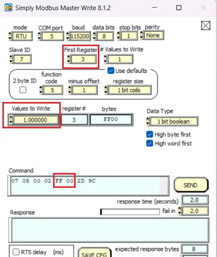
Here the master wants to modify the 3rd coil. The value to write is set to 1, and this makes the data bytes as 0xFF, 0x00.
Below the image shows the coil before and after the master requested the write operation.
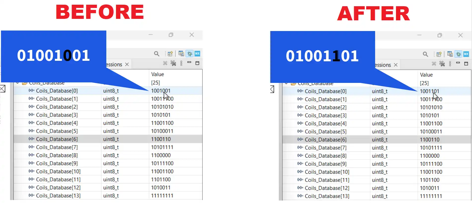
Here you can see the coil was disabled (0) before the data was sent by the master. And after the data was sent, the coil is set to 1.
Writing Multiple Coils
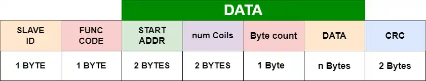
The Query format for writing multiple coils is shown below
uint8_t writeMultiCoils (void)
{
	uint16_t startAddr = ((RxData[2]<<8)|RxData[3]);  // start Coil Address

	uint16_t numCoils = ((RxData[4]<<8)|RxData[5]);   // number to coils master has requested
	if ((numCoils<1)||(numCoils>1968))  // maximum no. of coils as per the PDF
	{
		modbusException (ILLEGAL_DATA_VALUE);  // send an exception
		return 0;
	}

	uint16_t endAddr = startAddr+numCoils-1;  // Last coils address
	if (endAddr>199)  // end coil can not be more than 199 as we only have record of 200 (0-199) coils in total
	{
		modbusException(ILLEGAL_DATA_ADDRESS);   // send an exception
		return 0;
}- We find the Address of the start coil by using the RxData[2] and [3].
- Then we find the number of coils requested by the master. This information arrives in RxData[4] and [5].
- As per the standards, the master can write a maximum of 1968 coils at once. So if the master requests more than that, the slave will send an exception regarding ILLEGAL_DTATA_VALUE
- Next we will calculate the the address of the last coil (endAddr). Since I have defined the database for only 200 coils (0-199), if this end coil address exceeds 199th coil, the slave will send an exception regarding ILLEGAL_DATA_ADDRESS.
	/* Calculation for the bit in the database, where the modification will be done */
	int startByte = startAddr/8;  // which byte we have to start writing the data into
	uint16_t bitPosition = startAddr%8;  // The shift position in the first byte
	int indxPosition = 0;  // The shift position in the current indx of the RxData buffer

	int indx = 7;  // we need to keep track of index in RxData

	// Modify the bits as per the Byte received
	for (int i=0; i<numCoils; i++)
	{
		if (((RxData[indx]>>indxPosition)&0x01) == 1)
		{
			Coils_Database[startByte] |= 1<<bitPosition;  // replace that bit with 1
		}
		else
		{
			Coils_Database[startByte] &= ~(1<<bitPosition);  // replace that bit with 0
		}

		bitPosition++; indxPosition++;

		if (indxPosition>7)  // if the indxposition exceeds 7, we have to copy the data into the next byte position
		{
			indxPosition = 0;
			indx++;
		}
		if (bitPosition>7)  // if the bitposition exceeds 7, we have to increment the startbyte
		{
			bitPosition=0;
			startByte++;
		}
}- Now we will calculate the startByte, the byte in database where the modification will start from, the bitposition, which is the shift in the startByte, and the indxposition, which is to keep track of the bit in the RxData byte.
- The indx variable is defined to keep track of which byte of the RxData buffer we are reading. As the actual data starts from the RxData[7], it is defined as 7.
- In order to modify the database, we will shift the RxData to the right by the indxposition and extract the bit in that position.
- Based on if the bit is a ‘1‘ or a ‘0‘, we will write it to the respective bitposition in the database byte.
- We will the increment the bitposition and indxposition.
- If the bitposition is more than 7, we will increment the startByte so as to modify the next byte in the database.
- similarly if the indxposition is more than 7, we will increment the indx variable so as to read the next byte from the RxData buffer.
- Since we are extracting one bit at a time, the for loop repeats as many times as the number of coils requested by the master.
Once the modification is over, the slave will send a response to the master. The format for the response is shown below.
	// Prepare Response

	//| SLAVE_ID | FUNCTION_CODE | Start Addr | Data     | CRC     |
	//| 1 BYTE   |  1 BYTE       |  2 BYTE    | 2 BYTES  | 2 BYTES |

	TxData[0] = SLAVE_ID;    // slave ID
	TxData[1] = RxData[1];   // function code
	TxData[2] = RxData[2];   // Start Addr HIGH Byte
	TxData[3] = RxData[3];   // Start Addr LOW Byte
	TxData[4] = RxData[4];   // num of coils HIGH Byte
	TxData[5] = RxData[5];   // num of coils LOW  Byte

	sendData(TxData, 6);  // send data... CRC will be calculated in the function itself
	return 1;   // success
}Since the response is exactly the same as the first 6 bytes of what the master sent as the query, we will simply copy the data from RxData buffer and send it to the master.
Working
Below is the image showing the query sent by the master software.

Here the master wants to modify 8 coils, starting from the 65th coil. The data for each coil needs to be typed separately. Based on the 8 bit data, the data byte is going to be 0xD9.
Below the image shows the coil data before and after the write operation was performed
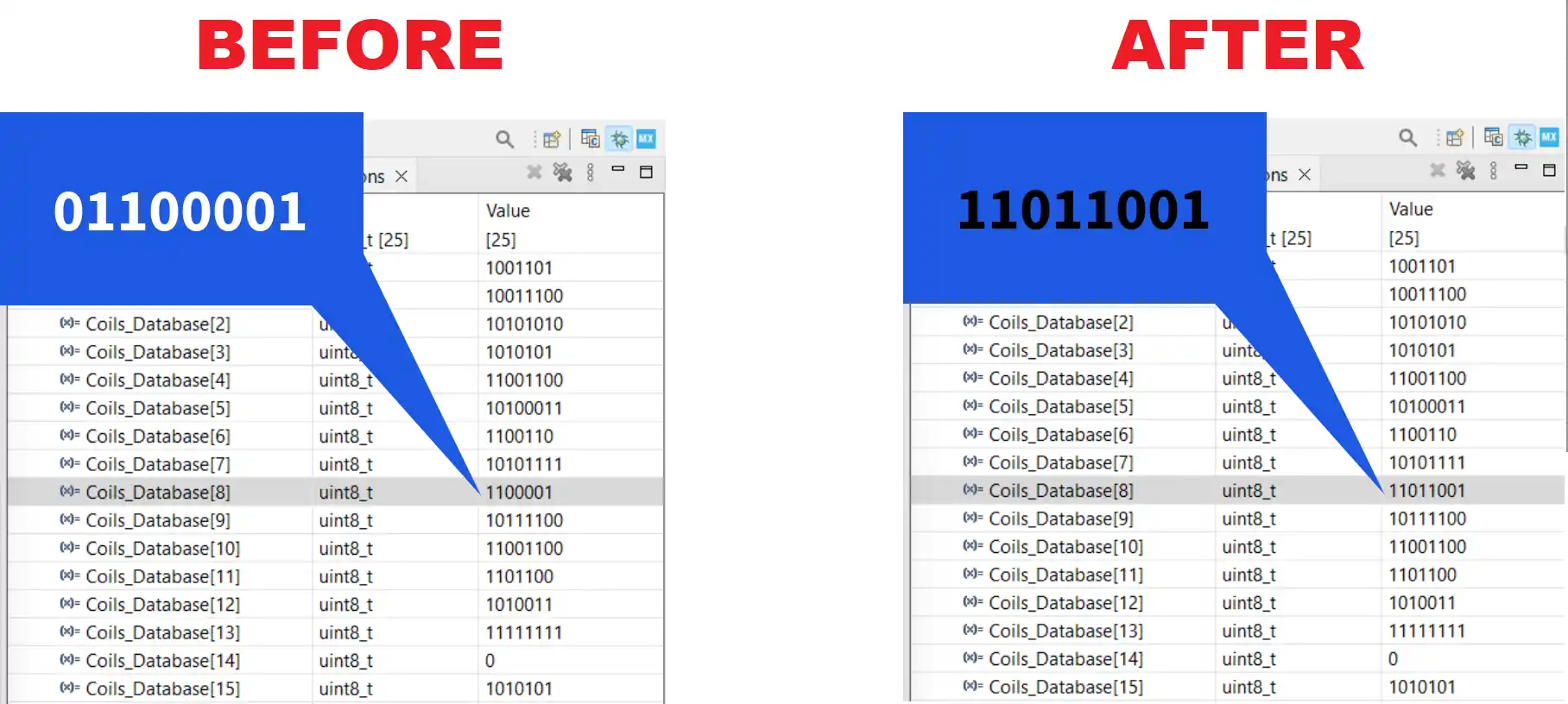
Here you can compare the coil values before and after the data was sent by the master.
STM32 Modbus RTU Tutorial Series

Modbus #1. STM32 Master Reads Holding and Input Registers

Modbus #2. STM32 Master Reads Coils and inputs

Modbus #3. STM32 Master Writes single Coil and Holding Register

Modbus #3.1 STM32 Master Writes Multiple Coils and Registers

Modbus #4. STM32 as Slave || Read Holding and Input Registers

Modbus #5. STM32 as Slave || Read Coils and Inputs

Modbus #6. STM32 as Slave || Write Registers

Subscribe
Login
0 Comments
Newest
