Esp8266 WebServer using STM32 HAL
I already covered How to manage multiple UARTs using ring buffer in STM32. You must have a knowledge of that, if you want to understand this one. Better take a look at that tutorial first.
Today, in this tutorial, we will use the ring buffer to manage a Esp8266 Webserver using STM32 HAL library. Basically, we will blink a LED using WiFi, by creating a webserver.
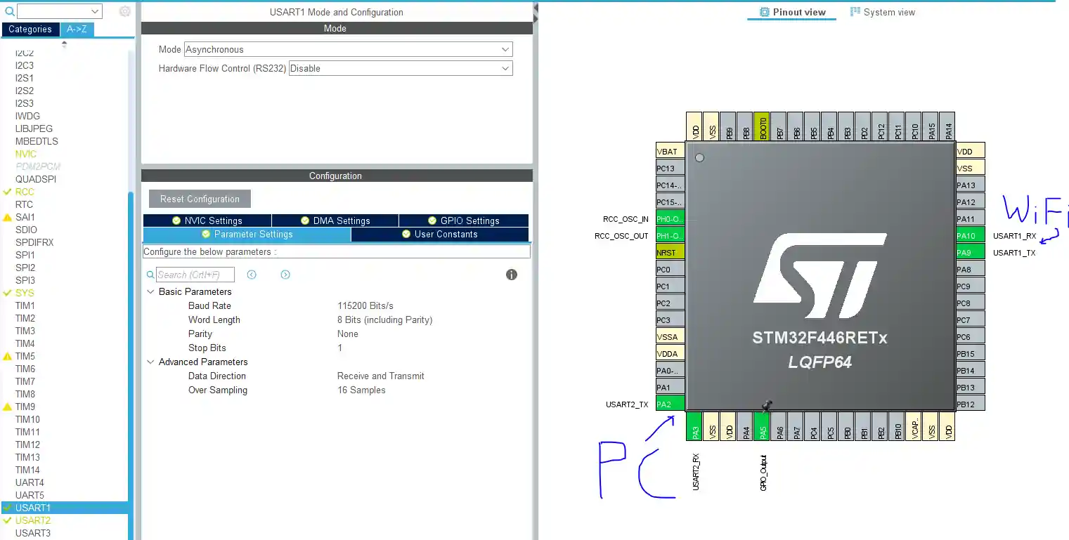
Below is the CubeMX setup. Two UARTs are being used. One is connected to the ESP8266, and another is connected to the computer.
VIDEO TUTORIAL
You can check the video to see the complete explanation and working of this project.
Connection & Configuration
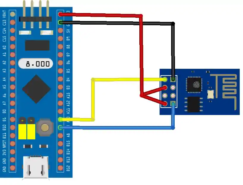
Below is the connection between the ESP8266 and the STM32.
Some Insight into the CODE
Let’s see some of the functions, that we are going to use
void ESP_Init (char *SSID, char *PASSWD)
{
	char data[80];

	Ringbuf_init();

	Uart_sendstring("AT+RST\r\n", wifi_uart);
	Uart_sendstring("RESETTING.", pc_uart);
	for (int i=0; i<5; i++)
	{
		Uart_sendstring(".", pc_uart);
		HAL_Delay(1000);
	}

	/********* AT **********/
	Uart_sendstring("AT\r\n", wifi_uart);
	while(!(Wait_for("AT\r\r\n\r\nOK\r\n", wifi_uart)));
	Uart_sendstring("AT---->OK\n\n", pc_uart);


	/********* AT+CWMODE=1 **********/
	Uart_sendstring("AT+CWMODE=1\r\n", wifi_uart);
	while (!(Wait_for("AT+CWMODE=1\r\r\n\r\nOK\r\n", wifi_uart)));
	Uart_sendstring("CW MODE---->1\n\n", pc_uart);


	/********* AT+CWJAP="SSID","PASSWD" **********/
	Uart_sendstring("connecting... to the provided AP\n", pc_uart);
	sprintf (data, "AT+CWJAP=\"%s\",\"%s\"\r\n", SSID, PASSWD);
	Uart_sendstring(data, wifi_uart);
	while (!(Wait_for("WIFI GOT IP\r\n\r\nOK\r\n", wifi_uart)));
	sprintf (data, "Connected to,\"%s\"\n\n", SSID);
	Uart_sendstring(data,pc_uart);


	/********* AT+CIFSR **********/
	Uart_sendstring("AT+CIFSR\r\n", wifi_uart);
	while (!(Wait_for("CIFSR:STAIP,\"", wifi_uart)));
	while (!(Copy_upto("\"",buffer, wifi_uart)));
	while (!(Wait_for("OK\r\n", wifi_uart)));
	int len = strlen (buffer);
	buffer[len-1] = '\0';
	sprintf (data, "IP ADDR: %s\n\n", buffer);
	Uart_sendstring(data, pc_uart);


	Uart_sendstring("AT+CIPMUX=1\r\n", wifi_uart);
	while (!(Wait_for("AT+CIPMUX=1\r\r\n\r\nOK\r\n", wifi_uart)));
	Uart_sendstring("CIPMUX---->OK\n\n", pc_uart);

	Uart_sendstring("AT+CIPSERVER=1,80\r\n", wifi_uart);
	while (!(Wait_for("OK\r\n", wifi_uart)));
	Uart_sendstring("CIPSERVER---->OK\n\n", pc_uart);

	Uart_sendstring("Now Connect to the IP ADRESS\n\n", pc_uart);

}ESP_Init (“SSID”, “PASSWD”) Initialises the ESP8266. Its parameter are the SSID and PASSWD of the Access point that you want to connect to. This function sends some AT commands in a sequence, and than waits for the expected response after every command. These commands are given below
- AT –> to check if the ESP is responding
- AT+CWMODE=1 –> to set the ESP into the station mode
- AT+CWJAP=”SSID”, “PASSWD” –> Join the access point with the SSID, and PASSWD
- AT+CIFSR –> Queries for the IP address of the ESP
- AT+CIPMUX=1 –> Set the multiple connection as TRUE
- AT+CIPSERVER=1,80 –> Starts a server at port 80
All the above information can be seen on the Serial console. Once the ESP gets the IP address, it will also be printed on the console as shown below

Next, we will connect to this IP address, but make sure the device and the ESP should be connected to the same network.
void Server_Start (void)
{
	char buftocopyinto[64] = {0};
	char Link_ID;
	while (!(Get_after("+IPD,", 1, &Link_ID, wifi_uart)));
	Link_ID -= 48;
	while (!(Copy_upto(" HTTP/1.1", buftocopyinto, wifi_uart)));
	if (Look_for("/ledon", buftocopyinto) == 1)
	{
		HAL_GPIO_WritePin(GPIOA, GPIO_PIN_5, 1);
		Server_Handle("/ledon",Link_ID);
	}

	else if (Look_for("/ledoff", buftocopyinto) == 1)
	{
		HAL_GPIO_WritePin(GPIOA, GPIO_PIN_5, 0);
		Server_Handle("/ledoff",Link_ID);
	}

	else if (Look_for("/favicon.ico", buftocopyinto) == 1);

	else
	{
		HAL_GPIO_WritePin(GPIOA, GPIO_PIN_5, 0);
		Server_Handle("/ ", Link_ID);
	}
}Server_Start() checks the incoming connection, and look for the request made by the browser. If the request is about ledon, or ledoff, or the root. Once identified, it will call the Server_Handle to handle that request
If the request is made for the root, or ledoff the following will be displayed on the browser
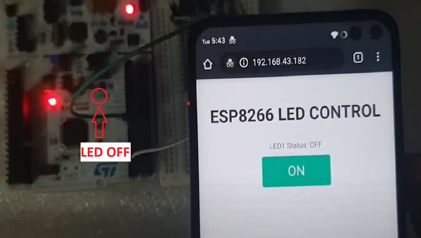
Note that the LED on board is OFF right now. There is a option displayed on the web browser to turn this LED ON.
If we tap this ON button, a ledon request will be sent to the ESP, and the Server_Start will call Server_Hnadle to handle this ledon request.
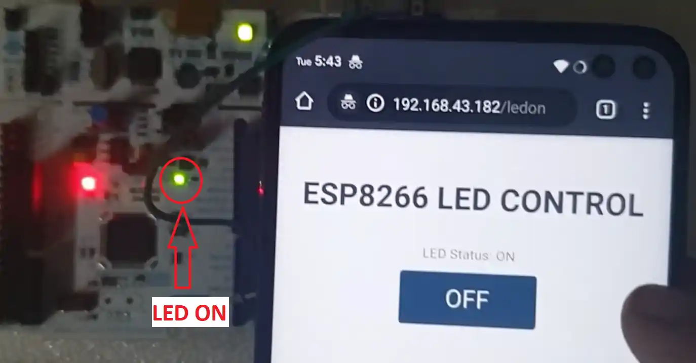
Now the LED is ON, and there is a OFF button to turn it OFF.
The web page source code is divided into 3 categories
- Initial part, where the basic stuff will load
- Button and Status part, which will depend on what request is being processed
- Ending part, which will close the tags
/**** Initial Part ****/
char *Basic_inclusion = "<!DOCTYPE html> <html>\n<head><meta name=\"viewport\"\
		content=\"width=device-width, initial-scale=1.0, user-scalable=no\">\n\
		<title>LED CONTROL</title>\n<style>html { font-family: Helvetica; \
		display: inline-block; margin: 0px auto; text-align: center;}\n\
		body{margin-top: 50px;} h1 {color: #444444;margin: 50px auto 30px;}\
		h3 {color: #444444;margin-bottom: 50px;}\n.button {display: block;\
		width: 80px;background-color: #1abc9c;border: none;color: white;\
		padding: 13px 30px;text-decoration: none;font-size: 25px;\
		margin: 0px auto 35px;cursor: pointer;border-radius: 4px;}\n\
		.button-on {background-color: #1abc9c;}\n.button-on:active \
		{background-color: #16a085;}\n.button-off {background-color: #34495e;}\n\
		.button-off:active {background-color: #2c3e50;}\np {font-size: 14px;color: #888;margin-bottom: 10px;}\n\
		</style>\n</head>\n<body>\n<h1>ESP8266 LED CONTROL</h1>\n";

/**** Button and Status Part ****/
char *LED_ON = "<p>LED Status: ON</p><a class=\"button button-off\" href=\"/ledoff\">OFF</a>";
char *LED_OFF = "<p>LED1 Status: OFF</p><a class=\"button button-on\" href=\"/ledon\">ON</a>";

/**** Ending Part ****/
char *Terminate = "</body></html>";To make this entire thing work, all you have to do is as shown below
/* USER CODE BEGIN Includes */
#include "ESP8266_HAL.h"

int main(void)
{
 .....
 .....
 .....
  ESP_Init("S9","12345678");

  while (1)
  {
    Server_Start();
  }
}In case you are using a microcontroller, which gave you error on Uart_isr function. Errors like DR and SR are not present, replace the Uart_isr code with the following file Uart_isr.c
Result


i am facing some random value in teraterm after debug, can you help?
I worked it in stm32f103, but it don’t copy the server id in pc terminal
please give the elaborated video regarding the pins.In my program i don’t getting any output
Bro It was great experience , I have accomplished this task, but now I need 2 to 3 button for home automation project, I have written code for 2 button , but It wont work, I think there is issue with the link ID , will you fig it out , I will share the code to you.
Can we add multiple button to control multiple leds in home automation using stm32 and esp01 8266
I am using Nucleo-f446re board, i am using cube IDE, i have given connection of PA9 to RX of esp-01 and PA10 to TX of esp-01 and 3.3v to 3.3v and gnd to gnd.
My Code is stuck at
while (!IsDataAvailable(uart));
if (Uart_peek(uart) != string[so_far])
{
_rx_buffer1->tail = (unsigned int)(_rx_buffer1->tail + 1) % UART_BUFFER_SIZE ;
goto again_device;
}
How to configure that ESP12E to the micro STM32? I just see RX wire to TX(stm32) and TX wire to RX(stm32). Where the usb cable connect?. and in the tutorial that is comunication micro to micro, Is the ESP12E have a program or a firmware before?
The tutorial is about ESP8266 module, not the micro.
If you are using micro, then make sure it is running the AT firmware (which works with AT Commands). You need to flash this firmware for your micro.
How fixed the “Reseting…” issue in STM32F103? i tried put GPIO0 and GPIO1 in 3V3 and still no feedback, just reseting….
Faced and solved similar issue.
The ESP_Init() is waiting for responses, which are different based on AT firmware version.
Example :
During the “Resetting…..” issue
Device waiting response,
while(!(Wait_for(“AT\r\r\n\r\nOK\r\n”, wifi_uart)));
Fix with the correct response,
while(!(Wait_for(“OK”, wifi_uart)));
Here is the list of AT responses I got from Arduino Serial Monitor:
*You might need to check yours.
AT
OK
AT+CWMODE=1
OK
AT+CWJAP=”ssid”,”pass”
WIFI CONNECTED
WIFI GOT IP
OK
AT+CIFSR
+CIFSR:STAIP,”ip_address”
+CIFSR:STAMAC,”mac_number”
OK
AT+CIPMUX=1
OK
AT+CIPSERVER=1,80
OK
did you get anything?
Hello,
I have tried to read your ring_buffer code,
It is not easy for me to see why you used ‘rx_buffer1’ and ‘_rx_buffer1’.
Would you explain the role of ‘rx_buffer1’ and ‘_rx_buffer1’?
sincerely yours,
Thanks for your ring_buffer code.
I got it to use a pointer with a structure on the ring_buffer code.
It shows very well how to access members of a structure using pointers.
Thanks again.
Hi, Great tutorials, learning a lot, many many thanks!
Using the ESP8266 with a Nucleo-STM32F756ZG and i am making progress. Currently, I am stuck at ESP_Init. I am monitoring incoming data to PC with Сutecom on Linux and it seems, that for every sendstring, only the first character is transmitted. Because of this, I am guessing, also the sendstring to the ESP8266 is not correct. Any idea, what could be the problem? Wrong UART setup? Would be happy, if I get some solution
Hello,
I have tried to port this program to stm32h7xx board, it was compiled well without error.
But there was no response from the board. And I have debugged it, it was stopped at the end of “Uart_write” function. I still did not know why it was stopped.
Would you help me?
Hello,
Thanks for the nice program to learn the usage of ESP8266 with STM32. I checked this program is worked very well in normal conditions.
I have interesting to run all programs on FreeRTOS.
So I am trying to run this program on FreeRTOS.
To check the possibility of it, I had tried two ways.
Just after FreeRTOS mode and configuration setup, I run it.
There was no message from the terminal.
And I moved two lines, as
void StartDefaultTask(void const * argument)
{
/* USER CODE BEGIN 5 */
ESP_Init(“staronic!_2G_5F”,”p21362136*”);
/* Infinite loop */
for(;;)
{
Server_Start();
osDelay(1);
}
/* USER CODE END 5 */
}
It generated a fault error.
How can I run this program on FreeRTOS?
I solved this problem, just extending the value of stack size as 518.
It worked very well on FreeRTOS.
Thanks for your nice blog to make a connection between STM32 with an internet.
Hello,
I am trying to run this job on stm32h743, but there is some compile error.
It is because usage of low-level interrupt call as
READ_REG(huart->Instance->SR) or
READ_REG(huart->Instance->DR)
the compiler generates an error because of usage of SR, DR.. et.al.
How can compile this program for stm32h743?
did you read the highlighted (in white colour) part above the “result” heading ?
Thanks for your quick and accurate comment. I got a solution with your comment. It was a big mistake to read your article roughly.
There was no compile error, if I changed “Uart_isr” with the highlighted part above the “result” heading. But there was no response from ESP8266. I think that another modification is needed to work on stm32h743.
Please help me.
Hello,
I am trying to get the ESP8266 module to work as a webserver with STM32F407, with the mentioned code changes (from the tutorial) added.
The UART1 is connected to the WIFI module as PA9 (TX1_STM) to RX_ESP and PB7 (RX1_STM) to TX_ESP.
The UART2 is connected as PA2 (TX2_STM) to RX_UART_MODULE and PA3 (RX2_STM) to TX_UART_MODULE, where UART_MODULE is an external UART converter connected to the PC.
I am flashing the code, but all I see on the PC terminal (BAUD rate and everything is set properly) is “RESETTING…..” and then it just hangs with no further change in the print.
Can you please help or suggest what could be going wrong?
PS: I tried a similar implementation with ARDUINO UNO and it worked properly. The example from here.
PLEASE HELP!!!!
i can’t download the code
Great tutorial!:)
hello I am not able to receive the ip address
i also not able to receive the ip address hercules screen shows only RESETTING……after that it stops from working…..what should i do so that i would be able to receive the ip address and open web page please help me.
Thanks in advance
Hi Lau Kian Siong,
Did you manage to get it working>??
Can you please let me know if and how you got it working??
Hello
If you can explain these 3 lines further:
while (! (Get_after (“+ IPD,”, 1, & Link_ID, wifi_uart)));
Link_ID – = 48;
while (! (Copy_upto (“HTTP / 1.1”, buftocopyinto, wifi_uart)));
What is transmitted in at-commands?
Link_ID – = 48;
(48)==???
That’s just to get an integer from an ASCII data.
Hello I am not able to receive the ip address hercules screen shows only RESETTING……after that it stops from working…..what should i do so that i would be able to receive the ip address and open web page please help me.
Thanks in advance
i also encounter same issue like u. how u solve it at the end, i use the different stm32board.
hi, i cant download the zip file whats the problem?
try now
This is a nice tutorial, I have sort of got it working but it randomly stops.
When i open the web pages it will let me toggle the LED on or off a few times, then the web page hangs, does anyone have any ideas?
When the page hangs, every time I refresh the page even though it doesnt work the ESP8266 LED flashes as if it is recieving the signal, but the STM doesnt send the webpage out
Any help is appreciated!
Thanks
I have followed the video, it works fine.
But when I try to use FreeRTOS and move the Server_Start() into a task then the task freezed. Need your suggestion, thanks.
void StartHTTP_Server(void const * argument)
{
/* USER CODE BEGIN StartHTTP_Server */
/* Infinite loop */
for(;;)
{
Server_Start();
HAL_GPIO_TogglePin(GPIOA,GPIO_PIN_5);
osDelay(1);
}
/* USER CODE END StartHTTP_Server */
}
it won’t work with freeRTOS.
Thanks for the answer.
Is there anyway I can have a HTTP server with FreeRTOS?
I, finally, found the answer.
Server_Handle() has declare an array of 4096 byte. this cause the function freezed.
I moved the array to be a global variable then the Server_Handle() works fine.
What I did may not be the best solution but at least it made us know the reason.
Would you be able to share that with me please? I have sort of got this project working but it hangs after toggling the LED a few times via the webpage and I have no idea why.
Thanks
Hello kind Gentleman’s
I would like to ask if there is any possibility for having both server_start function and code such as:
if(IsDataAvailable(pc_uart))
{
int data = Uart_read(pc_uart);
Uart_write(data, wifi_uart);
}
if(IsDataAvailable(wifi_uart))
{
int data = Uart_read(wifi_uart);
Uart_write(data, pc_uart);
}
in order of having simultaneously server and possibility to change config of ESP as shown in https://controllerstech.com/managing-multiple-uarts-in-stm32/ ??
Thank you in advance,
Love you all so much
i don’t think so. Server_start uses the blocking mode and look for the particular string in the incoming data. You can try this with freertos though. i am not sure that it would work
Tudo bem!
Muito bom seu trabalho, poderia postar um exemplo pro stm32f103?
This code works with F103 also. I have tested it myself
I download it and I did not find the library ESP8266 HAL in this file. So can you help me. Thank you so much
look in the src and inc folders
Bom dia!
copiei o exemplo para o stm32f103, o mesmo não responde na serial habilitei as interrupções!
watch the video. there is a lot more setup you needed to do, than to just copy.
I have tested it on f103 and it works fine
Desculpa como expressei, não apenas copiei habilitei as configurações do clube como interrupções da usart, más quando mando escrever qualquer comando AT dentro
void ESP_Init, a função trava já testei a função Uart_sendstring para escrever na serial uma string está funcionando.
I succeded, thanks for tutorial!
Não estou tendo sucesso teria como passa r como usou?