Joystick and STM32
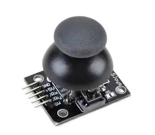
Today in this tutorial, I am going to interface Joystick module with STM32F103 controller. This module can be use for various purposes for eg- controlling a bot, or controlling the camera direction etc. As we know, the module gives analog output so it can be used for feeding the analog input based on direction or movement.
VIDEO TUTORIAL
You can check the video to see the complete explanation and working of this project.
CubeMX Setup
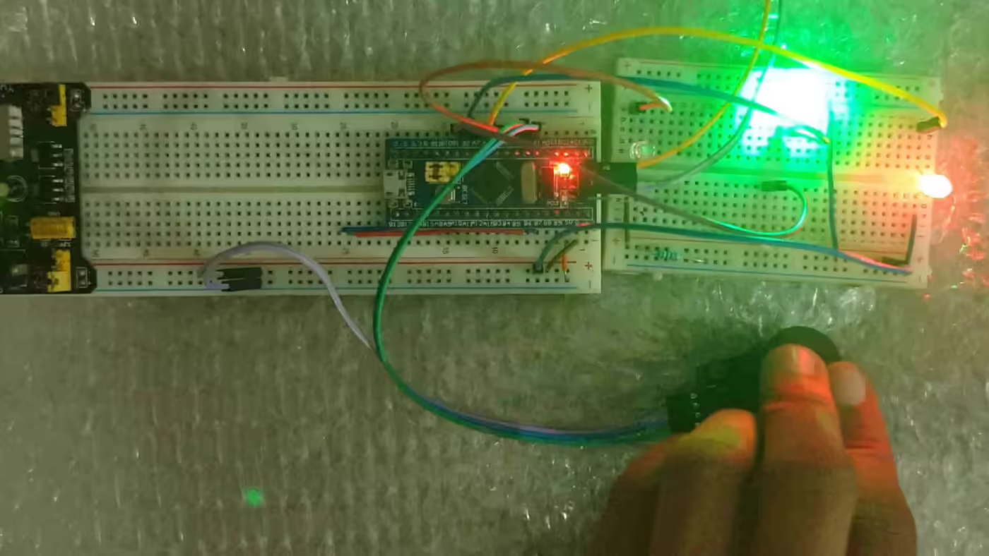
As the output from the Joystick pins is analogue, we will use ADC to read these Pins. And also I am going to use 4 LEDs to demonstrate the working. Below is the setup of cube mx

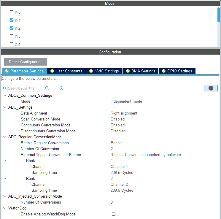
The ADC setup is shown below. I am using 2 channels i.e. channel 1 and channel 2 of the ADC1 to connect the 2 pins from the Joystick.
Some Insight into the CODE
To store the 12 bit ADC values, output from the joystick PINs, I have created an array of 2 variables.
uint32_t VR[2];As we are going to read Multiple channels of the ADC1, we have to use DMA to do so. In the above code, DMA is being used to read 2 channels of ADC1.
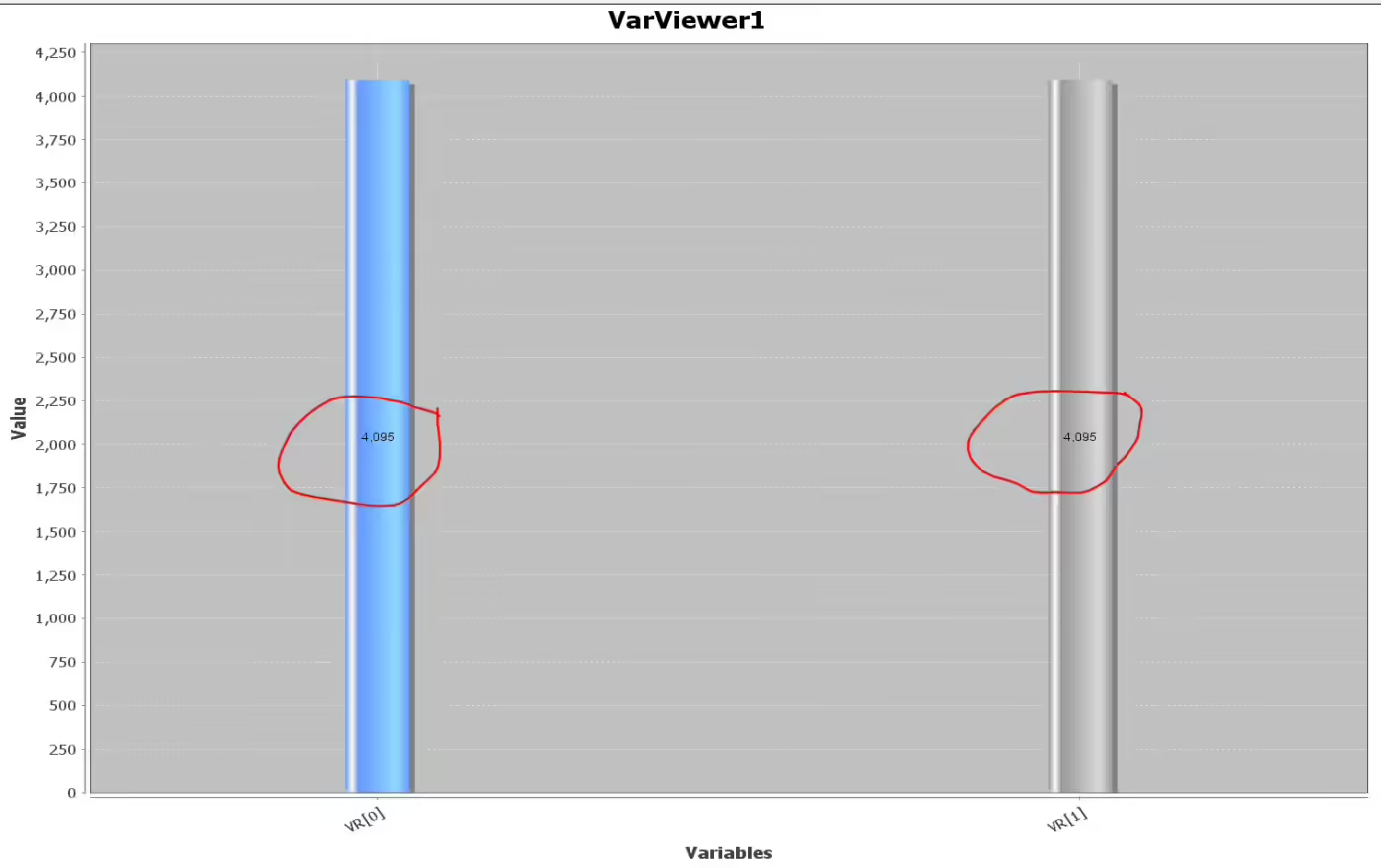
HAL_ADC_Start_DMA(&hadc1, VR, 2);ADC in STM32 is 12 bit by default, So the input values from the joystick are going to vary between 0 to 4095 (2^12). You can see that in the picture below
if ((VR[0]>=2000) && (VR[0]<=3000))
 {
  HAL_GPIO_WritePin(xmin_GPIO_Port, xmin_Pin, GPIO_PIN_RESET);
  HAL_GPIO_WritePin(xplus_GPIO_Port, xplus_Pin, GPIO_PIN_RESET);
 }

 if ((VR[1]>=2000) && (VR[1]<=3000))
 {
  HAL_GPIO_WritePin(ymin_GPIO_Port, ymin_Pin, GPIO_PIN_RESET);
  HAL_GPIO_WritePin(yplus_GPIO_Port, yplus_Pin, GPIO_PIN_RESET);
 }

 if ((VR[0]>=4000))
 {
  HAL_GPIO_WritePin(xmin_GPIO_Port, xmin_Pin, GPIO_PIN_RESET);
  HAL_GPIO_WritePin(xplus_GPIO_Port, xplus_Pin, GPIO_PIN_SET);
 }

 if ((VR[0]<=800))
 {
  HAL_GPIO_WritePin(xmin_GPIO_Port, xmin_Pin, GPIO_PIN_SET);
  HAL_GPIO_WritePin(xplus_GPIO_Port, xplus_Pin, GPIO_PIN_RESET);
 }

 if ((VR[1]>=4000))
 {
  HAL_GPIO_WritePin(ymin_GPIO_Port, ymin_Pin, GPIO_PIN_RESET);
  HAL_GPIO_WritePin(yplus_GPIO_Port, yplus_Pin, GPIO_PIN_SET);
 }

 if ((VR[1]<=800))
 {
  HAL_GPIO_WritePin(ymin_GPIO_Port, ymin_Pin, GPIO_PIN_SET);
  HAL_GPIO_WritePin(yplus_GPIO_Port, yplus_Pin, GPIO_PIN_RESET);
}- The above code is to toggle LEDs based on the orientation of the Joystick.
- If it is to the extreme left, the VR[0] = 0, and BLUE LED (xmin) will turn on.
- Similarly, wherever the joystick is moved, corresponding LED turns on. You can check the entire operation in the video below.
Result


Hi all, how can I use this code on STM32L476 nucleo-64 board ?
Thanks.
hello, firstly thanks so much and can you add again source code.
It’s updated now.