Home ▸ STM32 Tutorials ▸
Updated On: March 23, 2026
How to Setup DMA using Registers
This is another tutorial in the STM32 Register based programming series, and today we will see How to Setup DMA.
DMA is a very important part of any application, and if it’s available in your MCU, you should use it. DMA can copy data between peripheral and memory, and also between 2 memory locations, without affecting the CPU performance.
In STM32, there is a dedicated bus for the DMA, and this helps keeping the CPU free for other operations.
In this tutorial I will demonstrate the DMA usage using the UART, where we will copy the data from the UART Data Register to any memory location. We will also see how to handle the different interrupts in DMA.
The DMA setup will remain same across other peripherals also, so all you need to do is, just read this post carefully.
VIDEO TUTORIAL
You can check the video to see the complete explanation and working of this project.
DMA Configuration
Since I am using the DMA with UART, I would suggest that you go through the UART configuration also. Check it at https://controllerstech.com/how-to-setup-uart-using-registers-in-stm32/
Along with the configuration mentioned in the link posted above, we also need to enable the DMA in the UART. You must do that before enabling the transmitter or receiver. You can check the final code below.
Configuring the DMA is pretty simple. And the same configuration can be used in other peripherals also.
1. Which DMA to use
First of all we need to figure out which DMA (and channel) can we use. Every channel is associated with some particular peripheral, and we have to choose the channel according to our setup.
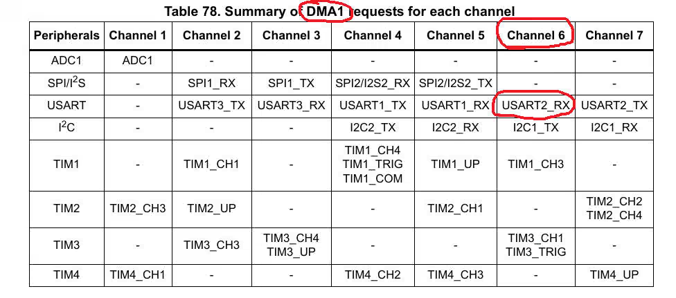
As you can see in the picture above that I have to use channel 6 of DMA 1 for the UART receive. Now the rest of the setup will be according to this.
2. Initialise the DMA
The DMA channel configuration register is where we are going to do our most of the setup. It is shown below
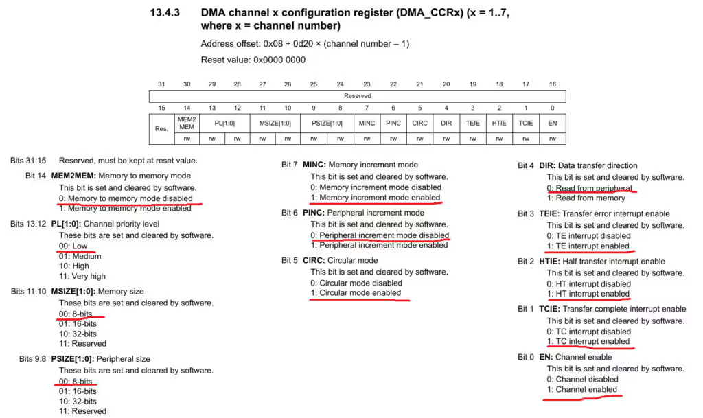
Below is the code to initialise the DMA
	// 1. Enable DMA1 Clock
	RCC->AHBENR |= 1<<0;

	// 2. Enable DMA Interrupts
	DMA1_Channel6->CCR |= (1<<1)|(1<<2)|(1<<3);  // TCIE, HTIE, TEIE Enabled

	// 3. Set the Data Direction
//	DMA1_Channel7->CCR |= (1<<4);   // Read From Memory
	DMA1_Channel6->CCR &= ~(1<<4);   // Read From Peripheral

	// 4. Enable the circular mode (CIRC)
	DMA1_Channel6->CCR |= 1<<5;

	// 5. Enable the Memory Increment (MINC)
	DMA1_Channel6->CCR |= 1<<7;

	// 6. Set the Peripheral data size (PSIZE)
	DMA1_Channel6->CCR &= ~(3<<8);  // 00 : 8 Bit Data

	// 7. Set the Memory data size (MSIZE)
	DMA1_Channel6->CCR &= ~(3<<10);  // 00 : 8 Bit Data

	// 8. Set the Priority Level
DMA1_Channel6->CCR &= ~(3<<12); // PL = 0- Here first of all we will enable the DMA 1 clock
- Now in the Channel Configuration, we will enable all the 3 interrupts i.e. Halt Transfer, Transfer Complete and Transfer Error
- As we are copying the data from peripheral to the memory, the Data direction should be set like that
- Next we will enable the circular mode for the DMA
- Then the peripheral address increment must be disabled, and Memory address increment must be enabled.
- This is because we copy the data from the Data Register of the peripheral, and that’s why it’s address must be constant
- On the other hand, the memory location should be incremented, so that the data can be copied into the new location.
- Next we will select the data size, which should be 8 bit.
- And finally we will set the priority level for the channel. I am keeping it 0 here, since I am only using 1 channel.
- But if you are using more than 1 channel, this priority level could be useful to set the priorities of the channels.
3. The final step is to configure the DMA
The configuration part for the DMA will cover the source and destination addresses, and how much data you want to copy. Below is the configuration function.
void DMA_Config (uint32_t srcAdd, uint32_t destAdd, uint16_t datasize)
{

	// 1. Set the data size in CNDTR Register
	DMA1_Channel6->CNDTR = datasize;

	// 2. Set the  peripheral address in PAR Register
	DMA1_Channel6->CPAR = srcAdd;

	// 3. Set the  Memory address in MAR Register
	DMA1_Channel6->CMAR = destAdd;

	// 4. Enable the DMA1
	DMA1_Channel6->CCR |= 1<<0;

}- Here we will write the source address in the Peripheral Address Register (CPAR), because we are copying the data from the peripheral.
- The memory address register will hold the address of the destination, where we are copying the data to.
- CNDR Register holds the number of data values that we want to copy.
- After configuring everything, we will enable the DMA
The Interrupt Handler
Once any of the above interrupts are triggered, we need to handle them. And to do that we will write an Interrupt handler for the DMA.
void DMA1_Channel6_IRQHandler (void)
{
	if ((DMA1->ISR)&(1<<22))  // If the Half Transfer Complete Interrupt is set
	{
		memcpy (&MainBuf[indx], &RxBuf[0], RXSIZE/2);
		DMA1->IFCR |= (1<<22);
		indx = indx+(RXSIZE/2);
		if (indx>49) indx=0;
	}

	if ((DMA1->ISR)&(1<<21))  // If the Transfer Complete Interrupt is set
	{
		memcpy (&MainBuf[indx], &RxBuf[RXSIZE/2], RXSIZE/2);
		DMA1->IFCR |= (1<<21);
		indx = indx+(RXSIZE/2);
		if (indx>49) indx=0;
	}

}- Here We will check which interrupt is triggered.
- Half Transfer will trigger, once the DMA have received half the data.
- For this interrupt, we will copy the first half of the buffer into the main buffer, and then clear the Interrupt (IFCR)
- The Transfer Complete interrupt will be triggered when the data has been completely received, and here we will copy the second half of the buffer into the main buffer.
- IFCR Register is used to clear the pending interrupt bit.
The main function
int main ()
{
	SystemInit();
	Uart2Config ();
	DMA_Init ();
	NVIC_SetPriority (DMA1_Channel6_IRQn, 0);
	NVIC_EnableIRQ (DMA1_Channel6_IRQn);
	DMA_Config ((uint32_t) &USART2->DR, (uint32_t) RxBuf, RXSIZE);
	while (1)
	{

	}
}- After initializing the UART and DMA, we will set up the interrupt for the DMA.
- I am keeping the priority 0, as this is the only interrupt I have here.
- Next we will configure the DMA.
- The source address will be the address of the Data Register of the UART
- Destination address will be the address of the memory location
- RXSIZE is the number of data items that we want to receive.
- As soon as the DMA is enabled, it will start looking for the data in the DATA Register.
- Once the data arrives, it will copy it to the memory location
- For every copy, the count in CNDTR Register will decrease.
- Since we are using the circular mode, once the value reaches 0, it will be auto reloaded to the original value.
- This way the DMA never stops in the circular mode.
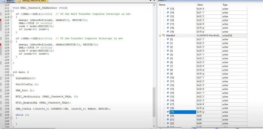
RESULT
Below is the picture where the data is received and saved in the main buffer. For more detailed working, check the video attached
STM32 Register based Tutorial Series

STM32F103 Clock Setup using Registers
STM32 GPIO Output Example Using Registers | BSRR, MODER, GPIOA Explained
STM32 GPIO Input Configuration – Pin Setup, Pull-Up, and IDR Read
STM32 I2C Tutorial | Register-Based Configuration with Example Code
External Interrupt using Registers
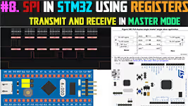
STM32 SPI Tutorial Using Registers (Full-Duplex Master with ADXL345)
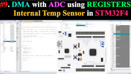
DMA with ADC using Registers in STM32


Really Helpful