Updated On: February 8, 2026
How to use one-wire Protocol to interface DS18B20
The 1-Wire protocol is widely used by sensors like the DS18B20 temperature sensor, but implementing it often requires precise timing and careful GPIO bit-banging. STM32 microcontrollers, however, offer a smarter alternative. By using the UART peripheral in single-wire (half-duplex) mode, it’s possible to emulate the 1-Wire protocol accurately without relying on software delays.
In this tutorial, we’ll explore how to implement the 1-Wire protocol using STM32 UART, focusing on communicating with the DS18B20 sensor. You’ll learn how UART baud rate manipulation and data encoding can match 1-Wire timing requirements, how reset and presence detection works, and how to read temperature data reliably. This approach results in cleaner code, better timing consistency, and a more robust solution compared to traditional bit-banging methods.
I have already covered how to interface DS18B20 using the GPIO mode. Today we will approach this sensor using the UART peripheral and see the resulting temperature value on the cubeIDE’s debugger.
Introducing the DS18B20 sensor
The DS18B20 is a digital temperature sensor that communicates using the 1-Wire protocol, allowing data transfer over a single data line along with ground. This makes the sensor very easy to interface with microcontrollers while also supporting multiple devices on the same bus. The DS18B20 provides temperature measurements in degrees Celsius with a programmable resolution from 9-bit to 12-bit, enabling a balance between accuracy and conversion time based on application requirements.
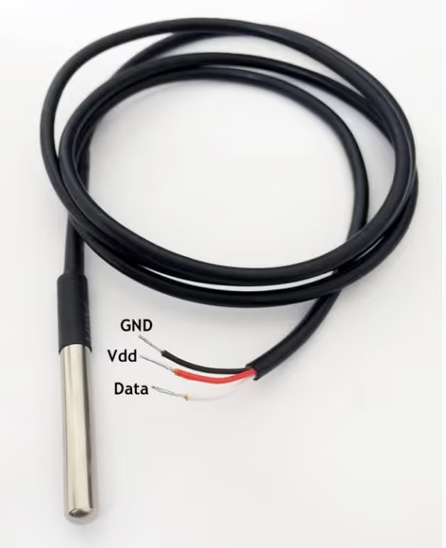
Another important feature of the DS18B20 is its calibrated digital output, which eliminates the need for external ADCs or analog signal conditioning circuits. Each sensor comes with a unique 64-bit ROM address, making it possible to identify and read data from multiple sensors connected to the same data line. The sensor can be powered either through an external supply or using parasite power mode, reducing wiring complexity in compact designs.
Advantages
- Simple 1-Wire interface requiring minimal GPIO usage
- Accurate and reliable digital temperature measurements
- No external ADC or signal conditioning required
- Supports multiple sensors on a single data line
- Optional parasite power operation reduces hardware components
Applications
- Industrial and embedded temperature monitoring systems
- HVAC and climate control applications
- Environmental monitoring and data logging
- Weather stations and outdoor sensing
- Smart home and IoT-based temperature measurement systems
How does the DS18B20 communicate ?
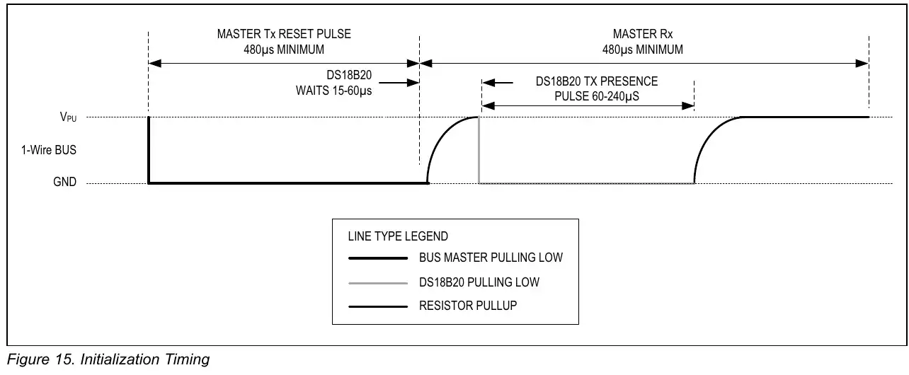
Initialization
The image below shows the initialisation timing of the DS18B20.
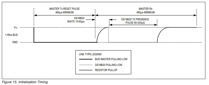
As show above, we need to pull the line LOW for around 480us and then release it. Then the sensor waits for around 60us and pull the line LOW for 60 – 240us to show its presence on the line.
Note:
You might need to connect pull-up resistance to the data line or else DS18B20 will not be able to pull it HIGH.
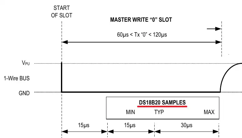
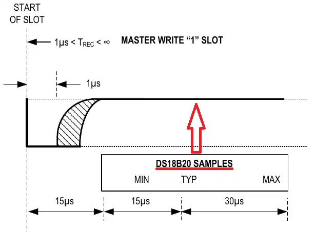
Write Timing
The images below shows the timing required to write a single bit to the sensor.
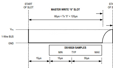
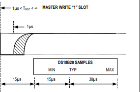
- To generate a Write 0 time slot, after pulling the line low, the master must continue to hold the line low for the duration of the time slot (at least 60µs).
- To generate a Write 1, after pulling the line low, the master must release the line within 15µs.
- When the bus is released, the 5kΩ pullup resistor will pull the bus high.
Read Timing
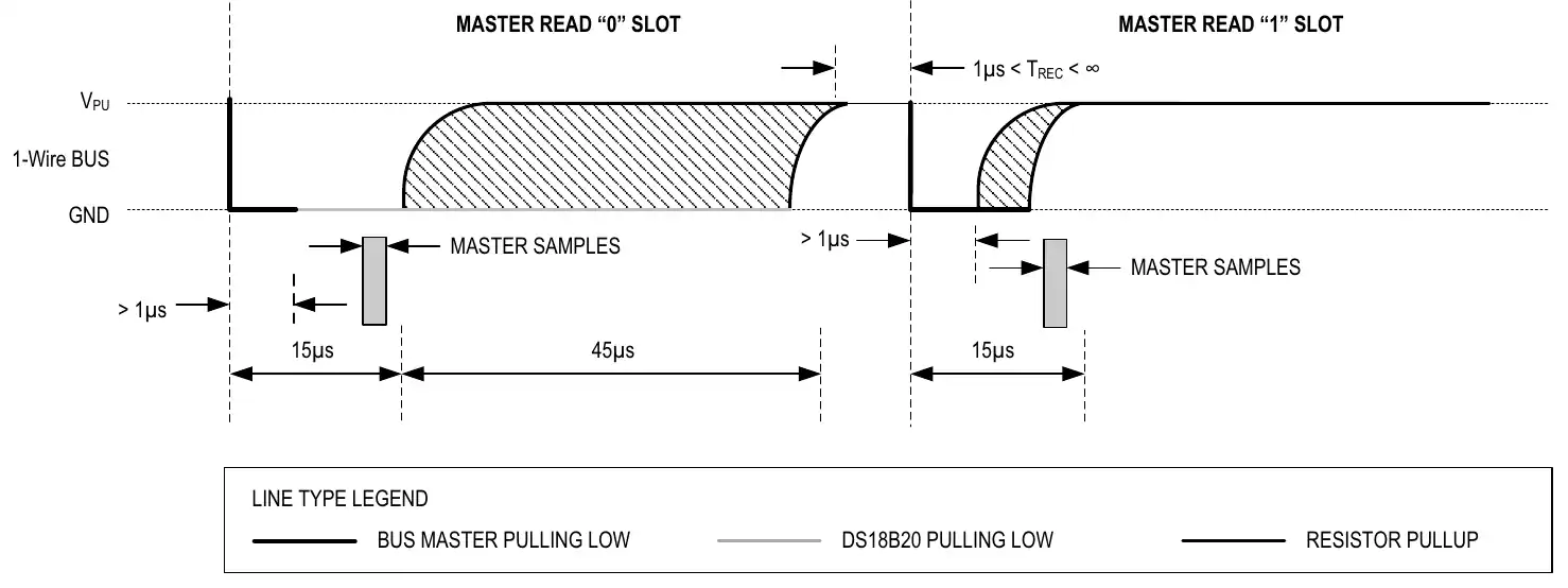
The image below shows the Timing to read a single bit from the sensor.
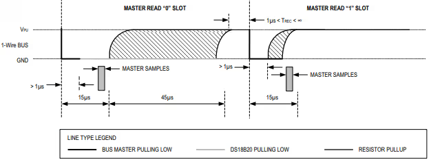
- A read time slot is initiated by the master device pulling the 1-Wire bus low for a minimum of 1µs and then releasing the bus.
- After the master initiates the read time slot, the DS18B20 will begin transmitting a 1 or 0 on bus.
- It transmits a 1 by leaving the bus high and transmits a 0 by pulling the bus low.
- When transmitting a 0, the sensor will release the bus by the end of the time slot, and the bus will be pulled back to its high idle state by the pull-up resister.
STM32CubeMX Configuration
We will use the UART Half-Duplex mode to communicate with DS18B20. The image below shows the UART configuration.
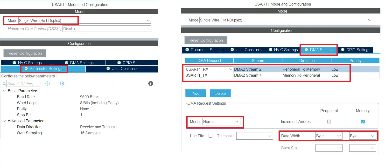
USART1 is configured to operate in single-wire (half-duplex) mode, allowing the same data line to be used for both transmission and reception.
The UART is set up with 8 data bits, 1 stop bit, and no parity. Since the baud rate is changed dynamically during operation to meet the 1-Wire timing requirements, the initial baud rate configured here is not critical.
DMA is enabled for both UART transmit and receive, operating in normal mode with the data width set to byte. Using DMA ensures reliable timing and reduces CPU involvement during data transfers.
Wiring Diagram for DS18B20
Below is the image showing the connection between the STM32 and the DS18B20 sensor.
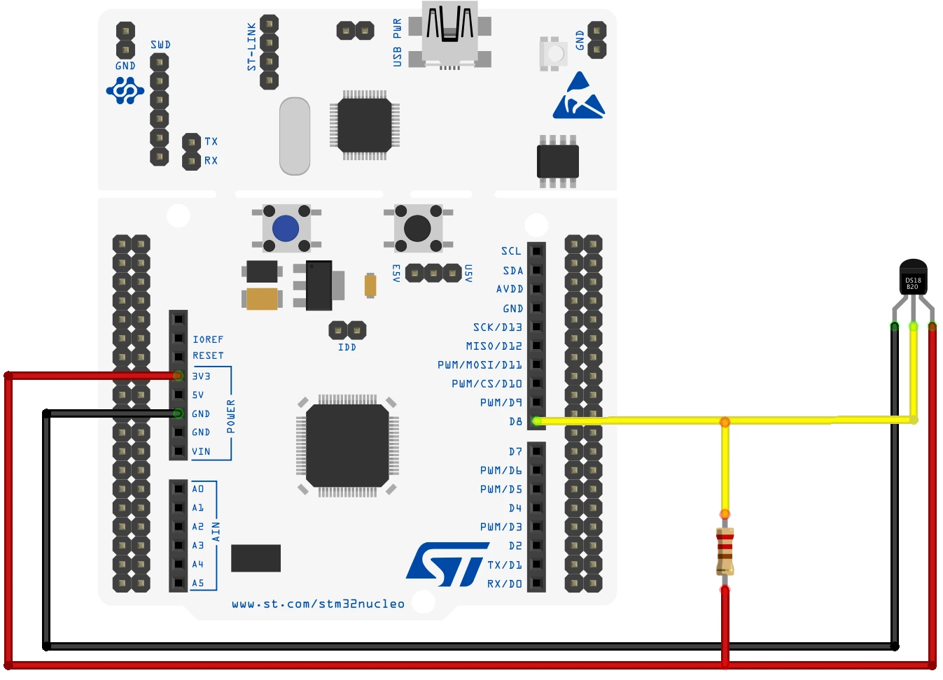
In single wire mode, we only have one pin for the TX. The sensor is connected to the TX pin of the USART1.
The sensor is powered by 3.3V from the MCU itself and there is a pull up resistor of 2K, connected between the data line and the 3.3V.
How to Send Data (0 and 1 ) to the sensor
We need to send the data to the sensor and read the data from it. The sensor require different timing signal for a bit to recognize it as a bit 0 or bit 1. We will cover this in depth below.
MCU send bit ‘0’
As per the information given in the DS18B20 datasheet, for the sensor to recognize a signal as the bit 0, the data line should transit from HIGH to LOW and then it should be LOW for around 60-120us.
Now if we use the UART at the baud rate of 115200, each bit would take around 8.68us. We are using 8 Data bit, so along with the Start bit we have a total of 9 bits in a single byte. These 9 bits would take around 78us in total.
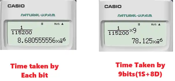
The START bit is always LOW in UART. So to transmit the bit 0, we will send the byte 0x00. This will transmit 9 Low bits (Start bit + 8 Data bits) and will keep the data line Low for around 78us. It will satisfy the criteria for the bit 0.
Below is the image showing the data line on the Logic Analyzer. This image shows the data line timing, when we send the data byte 0x00.
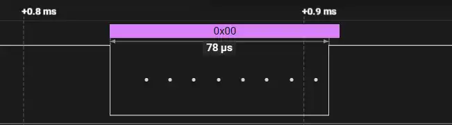
As you can see the line transits from High to Low. This is the START bit followed by the 8 Low data bits. The total time taken by the data byte is around 78us. This time is even less when we connect an actual sensor to the data line.
Therefore, to send the bit 0 to the sensor, the MCU needs to send the byte 0x00.
MCU send bit ‘1’
As per the information given in the DS18B20 datasheet, for the sensor to recognize a signal as the bit 1, the data line should transit from HIGH to LOW and then it should be LOW for around 1us. After that the line should be released and the pull up resistor will pull the line High for the rest of the time.
Since each bit at the baud rate of 115200 takes around 8.68us, it is not possible for the MCU to pull the line low for just 1us, it will at least be low for 8.68us.
One interesting point to note is that the DS18B20 sensor does not sample the line immediately after 1us. Instead it will only sample 15us after the line was first pulled low. We will send the data 0xFF, such that only the START bit is low and the rest of the bits are high. This will keep the line low for only around 9-10us and then the line will be pulled High with the help of the pull up resistor.
By the time the sensor samples the line (after 15us) the line would already be high.
Below is the image showing the data line on the Logic Analyzer. This image shows the data line timing, when we send the data byte 0xFF.
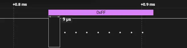
As you can see the line transits from High to Low. This is the START bit followed by the 8 High data bits. The time for which the line is low is around 9us. This time is even less when we connect an actual sensor to the data line. For the rest of the time the line is High. So when the sensor will sample the line (after 15us), it will already be high.
Therefore, to send the bit 1 to the sensor, the MCU needs to send the byte 0xFF.
How to Send the Reset Condition
To send the reset condition, the master needs to pull the line low for a minimum of 480us and then release it. When the DS18B20 detects this rising edge, it waits 15μs to 60μs and then transmits a presence pulse by pulling the line low for 60μs to 240μs.
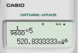
With the baud rate of 115200, the total time taken by 9 bits (Start + 8Data bits) is less than 80us. So we can not possibly pull the line Low continuously for at least 480us. This is why we will use the baud rate of 9600 to send the reset condition.
If the master send the byte 0xF0 with the baud rate of 9600, there will be 5 Low bits (Start + 4 Data bits). The total time for which the line will remain low will be around 520us.
Below is the image showing the output of sending the byte 0xF0 with the baud rate of 9600.
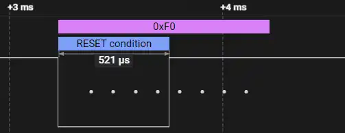
As you can see the 1-wire analyzer does detect the pulse as the Reset condition.
When the sensor detects the reset pulse, it will send the presence pulse by pulling the line Low again. It does that immediately after seeing that the line is released by the master. As a result, the byte 0xF0 is changed to something else. You can see this in the image below.
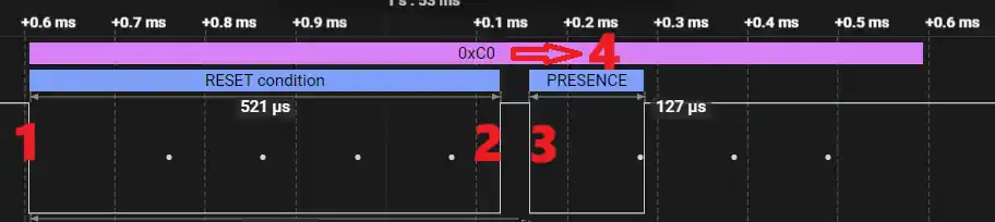
- The master starts transmitting the reset pulse by pulling the line Low. It wants to transmit the byte 0xF0.
- After transmitting the first 4 bits (0 0 0 0), the master releases the line, so that it can transmit last 4 bits (1 1 1 1).
- The sensor sees the line is released, so it waits for 15-60us and pulls the line back Low for around 60-240us.
- As a result of this, the byte 0xF0 has been change to some other byte (0xC0 in this case).
Therefore, to send the reset condition and read the presence pulse, we will send the byte 0xF0 at the baud rate of 9600. We will then read the data received by the UART. If the data is different than 0xF0, we will come to a conclusion that the sensor must have pulled the line Low and hence it sent the presence pulse.
How to read Data (0 & 1) from DS18B20
After receiving the appropriate commands, the sensor will start sending the temperature data bytes. The MCU needs to read these bits and extract the temperature from it.
The master will first pull the line Low for around 1us and then release it. If the sensor wants to send the bit 0, it will pull the line Low again, and if the master wants to send the bit 1, it will leave the line released. This can be seen in the image below.
The master can sample the line before 15us. If the line is Low, it can assume that it is a bit 0 and if the line is High, it can assume that the bit is 1.
To pull the line low for just around 1us, the master will send the byte 0xFF at the baud rate of 115200. This data will only contain a Low start bit whereas for the rest of the time, the line will remain High. When the sensor sees the line is released after the Start bit, it will either pull it Low again to transmit the bit 0 or leave it High to transmit the bit 1.
Since the master wants to read an entire byte, it needs to keep sending the byte 0xFF a total of 8 times. For each byte, the sensor can respond with either bit 0 or bit 1.
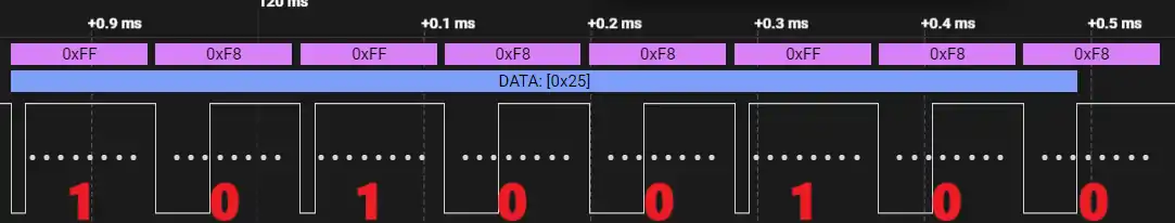
You can see in the image above, the master transmitted 8 bytes containing 0xFF. The master transmitted the bit 0 by pulling the line Low for some of these bytes while the rest of the bytes are untouched and we got the same data that we sent.
Therefore, to read the data from the sensor, the master will send 8 bytes data containing the byte 0xFF. It will then read the data received by the UART. If the data is different than 0xFF, the sensor must have pulled the line Low and hence the bit is a 0. Whereas if the data is same as 0xFF, the bit is a 1.
STM32 HAL Code to interface DS18B20
The DS18B20_Start function will be used to send the Reset to the sensor and detect the presence pulse.
int DS18B20_Start(void)
{
	uint8_t data = 0xF0;
	uart_init(9600);
	HAL_UART_Transmit(&huart1, &data, 1, 100);  // low for 500+ms
	if (HAL_UART_Receive(&huart1, &data, 1, 1000) != HAL_OK) return -1;   // failed.. check connection
	uart_init(115200);
	if (data == 0xF0) return -2;  // no response.. check connection
	return 1;  // response detected
}We will first initialize the UART with the baud rate of 9600. Then transmit the data byte 0xF0 as discussed above. We will then receive 1 byte of data from the UART and store it in the data variable. The rest of the UART operations will take place at the baud rate of 115200, so initialize the UART with this baud.
If the received data is same as 0xF0, this means that the presence pulse has not been detected and we will return an error. Otherwise if the sensor has pulled the line Low, the received data will be different from 0xF0. This means the presence pulse is detected, so we will return success.
The DS18B20_Write function will be used to write the data byte to the sensor. The parameter of this function is the data byte that we want to send to the sensor.
void DS18B20_Write (uint8_t data)
{
  uint8_t buffer[8];
  for (int i=0; i<8; i++)
  {
    if ((data & (1<<i))!=0)  // if the bit is high
    {
	buffer[i] = 0xFF;  // write 1
    }
    else  // if the bit is low
    {
	buffer[i] = 0;  // write 0
    }
  }
  HAL_UART_Transmit(&huart1, buffer, 8, 100);
}We need to send 8 bits to the sensor. Each bit will be sent as a byte and hence we will send 8 bytes in total. This is why the array buffer is defined to store 8 bytes.
We will extract each bit from the data. If the bit is a 1, we will store the byte 0xFF to that position and if the bit is a 0, we will store 0x00 to that position. This has already been explained above in the writing process.
After storing the relevant bytes to the buffer array, we will send the array to the UART.
The function DS18B20_Read will be used to read the data byte sent by the sensor. This function returns the data byte received.
uint8_t DS18B20_Read (void)
{
	uint8_t buffer[8];
	uint8_t value = 0;
	for (int i=0; i<8; i++)
	{
		buffer[i] = 0xFF;
	}

	HAL_UART_Transmit_DMA(&huart1, buffer, 8);
	HAL_UART_Receive_DMA(&huart1, RxData, 8);

	while (isRxed == 0);
	for (int i=0;i<8;i++)
	{
		if (RxData[i]==0xFF)  // if the pin is HIGH
		{
			value |= 1<<i;  // read = 1
		}
	}
	isRxed = 0;
	return value;
}I have already explained in the Reading Process that the master needs to send 8 bytes containing the value 0xFF. Since we want to record the response of the sensor to each byte transmitted, it is better to send the data using the DMA. This way the response will be recorded in simultaneous with the data transmission.
The variable isRxed will be set inside the DMA callback when all the 8 data bytes has been received. Once that happens, we will start converting the received data bytes into the bits.
If the received data is same as 0xFF, that implies that the bit is a 1 otherwise if the received data is something else, the bit is a 0. We will analyze the received data buffer, and store the bit 1 or bit 0 at the respective position in the value variable.
After all the received data bytes has been processed, we will reset the variable isRxed to 0 and return the value.
The main function
Inside the main function, we will continuously read the temperature after a particular interval. This is why the code is inside the while loop.
int main ()
{
  ...
  ...
  while (1)
  {
     Presence = DS18B20_Start ();
     DS18B20_Write (0xCC);  // skip ROM
     DS18B20_Write (0x44);  // convert t

     Presence = DS18B20_Start ();
     DS18B20_Write (0xCC);  // skip ROM
     DS18B20_Write (0xBE);  // Read Scratch-pad

     Temp_LSB = DS18B20_Read();
     Temp_MSB = DS18B20_Read();
     Temp = ((Temp_MSB<<8))|Temp_LSB;
     Temperature = (float)Temp/16.0;  // resolution is 0.0625

     HAL_Delay(2000);
  }
}We will read the data as according to the information given in the datasheet. Basically the master will send the reset sequence and detect the presence pulse. Then it will issue the skip rom command followed by the convert t command.
It will again send the reset condition and read the presence pulse. It will then send the skip rom command followed by the read scratchpad command.
Then the master will request 2 bytes data from the sensor. It will first read the Least Significant Byte followed by the Most Significant Byte of the temperature data.
The sensor is configured with 12 bit resolution by default. Hence we will have a total of 12 bits of the data. The 2 bytes of the temperature data will be combined to form a single 12 bit data.
With the resolution of 12 bit, the temperature is set to 0.0625 °C per bit value. Hence to convert the 12 bit temperature data to actual temperature, we will multiply the 12 bit value with 0.0625 or divide by 16.
DS18B20 Output Data on STM32
Below is the image showing the values on the cubeIDE debugger window.
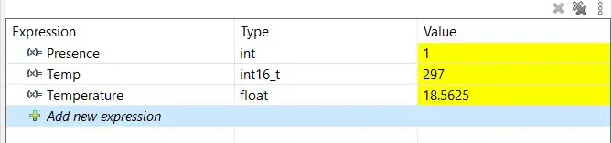
You can see the presence value is 1, which means that the sensor was detected. The final Temperature is around 18.5°C.
To see the full working where the sensor responds to the change it temperature, check out the video below.
Video Tutorial
STM32 UART 1-Wire Protocol (DS18B20) – Video Tutorial
This video demonstrates how to implement the 1-Wire protocol using the STM32 UART peripheral to interface with a DS18B20 temperature sensor. It covers single-wire (half-duplex) configuration, baud rate switching, reset and presence detection, and reading temperature data using HAL.
Watch the VideoConclusion
Using the UART peripheral to implement the 1-Wire protocol on STM32 provides a clean and reliable alternative to traditional GPIO bit-banging. By combining single-wire (half-duplex) mode with carefully chosen baud rates, the STM32 can accurately meet the timing requirements of devices like the DS18B20. This approach simplifies the code, improves timing consistency, and makes the communication less sensitive to CPU load.
Once the basic reset, presence detection, and read/write sequences are understood, this technique can be extended to other 1-Wire devices and more complex applications. Leveraging hardware peripherals such as UART and DMA not only improves robustness but also frees up the CPU for other tasks, making this method well suited for real-world embedded systems where reliability and efficiency matter.
Browse More STM32 UART Tutorials
STM32 UART Part 3 – Receive Data in Blocking & Interrupt mode
STM32 UART DMA Receive: Normal & Circular Mode (HAL)
STM32 UART Idle Line: Receive Data via Interrupt & DMA
STM32 UART Part 6 – Half-Duplex Communication (Single-Wire Mode)
STM32 UART Part 8 – LIN Communication Tutorial
STM32 UART Part 9 – LIN Transceiver Connections & Master-Slave Communication
STM32 UART PART 10 – Lin Protocol PART 3
STM32 UART One-wire Project Download
STM32 UART One-wire FAQs


DS18B20 pinout on fritzing schematic is wrong