Home ▸ STM32 Tutorials ▸
Updated On: June 20, 2026
How to Port the U8G2 Graphics Library to STM32
Writing your own display driver for every new OLED or LCD is time consuming and error-prone. U8G2 solves that as it supports over 100 display controllers out of the box, handles its own fonts and drawing primitives, and only asks you to write two small callback functions that bridge it to your MCU’s hardware.
This tutorial shows you how to port the U8G2 monochrome graphics library to STM32 using three communication methods: hardware SPI (1.3″ SH1106 OLED), hardware I2C (0.96″ SSD1306 OLED), and software SPI (HX1230 graphic LCD). You’ll configure STM32CubeMX, implement the GPIO/delay and byte communication callbacks following the official U8G2 porting guide, and display text and shapes on all three. The complete CubeIDE project is available to download below.
Working with individual display drivers instead? Check out the STM32 OLED tutorials collection for standalone drivers: the SSD1306 I2C tutorial, the SH1106 I2C tutorial, and the STM32 LCD tutorials for character LCD options.
What Is the U8G2 Library?
U8G2 (Universal 8-bit Graphics Library) is an open-source monochrome graphics library built for embedded systems. It supports OLED, LCD, and ePaper displays and runs on AVR, STM32, ESP32, Arduino, and more. The library is maintained on GitHub and includes an official porting guide that this tutorial follows.
Key Features
- Wide display support — over 100 controller ICs including SSD1306, SH1106, ST7565, ST7920, and HX1230.
- Multiple protocols — hardware SPI, hardware I2C, software SPI, and software I2C are all supported.
- High-level drawing API — built-in functions for text, lines, rectangles, circles, and bitmaps via the U8G2 reference manual.
- Rich font library — proportional and fixed-width fonts in multiple sizes, selectable with a single call.
- Flexible memory modes — choose between full-buffer, page-buffer, or no-buffer rendering to match your MCU’s available RAM.
Buffer Modes: Full, Page, and No-Buffer
The suffix on every U8G2 setup function tells you which mode it uses:
| Suffix | Mode | RAM used | How to push to display |
|---|---|---|---|
_f | Full buffer | Entire framebuffer in RAM | Call u8g2_SendBuffer() once |
_2 | Two-page buffer | 2 pages of RAM | Use the page-loop pattern |
_1 | One-page buffer | 1 page of RAM | Use the page-loop pattern |
Full buffer (_f) is the simplest — draw everything, then call u8g2_SendBuffer(). Use page-buffer modes (_1, _2) on MCUs with limited RAM, such as the STM32F103 with 20 KB of SRAM. This tutorial uses _f throughout for clarity.
The Two Callbacks You Need to Implement
According to the official U8G2 porting guide, porting to a new MCU requires implementing exactly two functions:
1. u8x8_gpio_and_delay — handles all GPIO pin writes (CS, DC, RESET, SPI clock/data for soft SPI) and timing delays (millisecond and nanosecond).
2. u8x8_byte_* — handles the actual byte-level communication: signalling a transfer start, sending data bytes, and signalling a transfer end. For hardware SPI and I2C you write a custom version; for software SPI you can use a predefined U8G2 callback (u8x8_byte_3wire_sw_spi) and skip writing this one entirely.
Every other detail like initialization sequences, page addressing, font rendering is handled internally by U8G2.
Library Setup in STM32CubeIDE
Download U8G2 from GitHub
Go to the U8G2 GitHub repository and download or clone the repository as a ZIP file.

Extract the ZIP. Inside you will find the csrc folder — this contains all the U8G2 source and header files and is the only folder you need.
Add csrc to Your CubeIDE Project
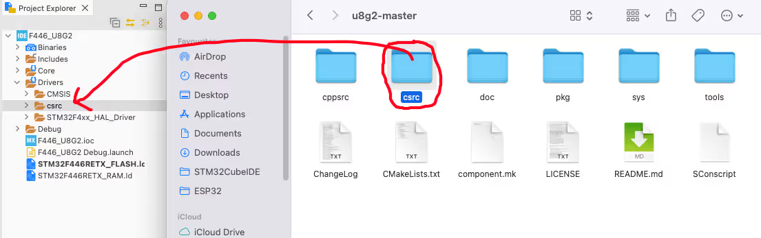
Copy the entire csrc folder and paste it into the Drivers folder of your CubeIDE project. You should now have a path like:
YourProject/
  Drivers/
    csrc/         ← U8G2 source files
    STM32F4xx_HAL_Driver/
CMSIS/Configure the Include Path
CubeIDE needs to know where to find the U8G2 headers.
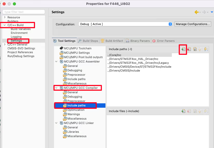
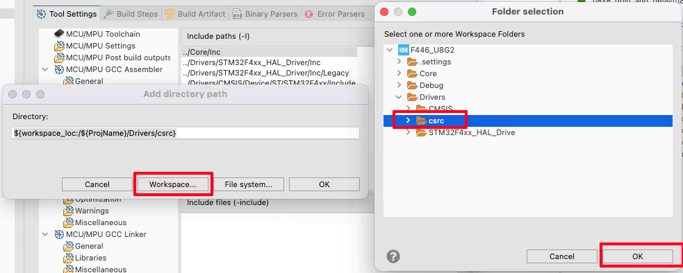
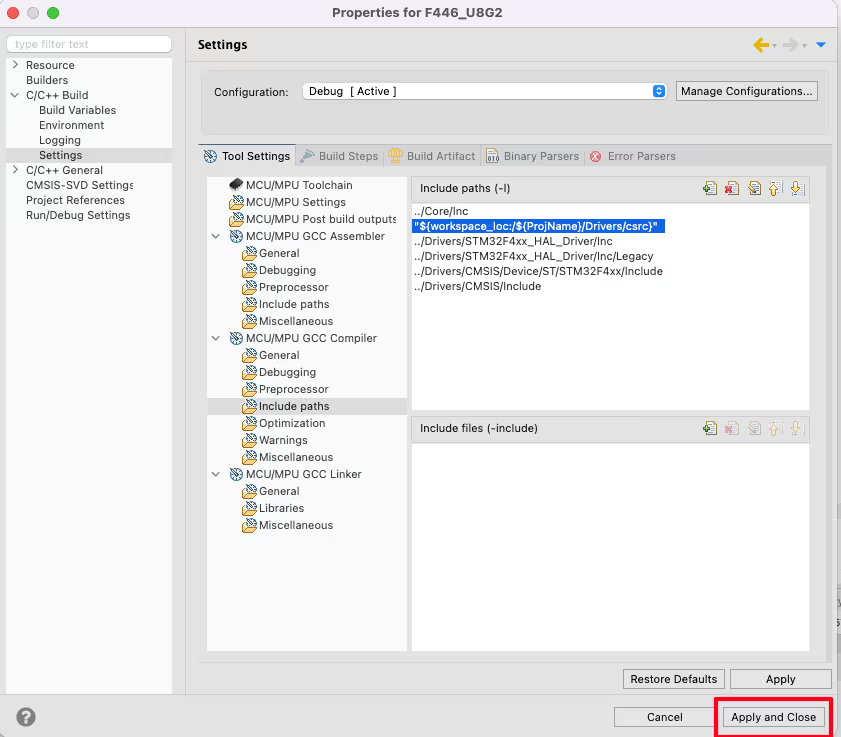
Open Project → Properties → C/C++ Build → Settings → GCC Compiler → Include Paths. Click Add, then Workspace, browse to the csrc folder inside Drivers, and click OK. Click Apply and Close.
With this done, #include "u8g2.h" will resolve correctly in any source file.
Hardware SPI — SH1106 1.3″ OLED
CubeMX SPI1 Configuration
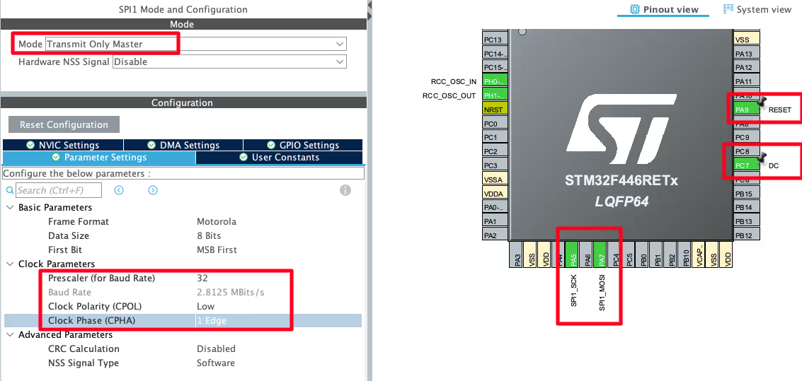
Enable SPI1 in CubeMX and configure:
- Mode: Transmit Only Master — no data comes back from the display, so MISO is unused.
- Baud rate: ~3 Mbit/s — fast enough for smooth updates, conservative enough to avoid signal integrity issues on jumper wires.
- CPOL: Low, CPHA: 1 Edge — this is SPI Mode 0.
Configure PA9 as a GPIO Output and label it RESET. Configure PC7 as GPIO Output and label it DC. Configure PB6 as GPIO Output and label it CS. These three control pins are driven manually in the callback, not by the SPI peripheral.
Wiring — SH1106 to STM32
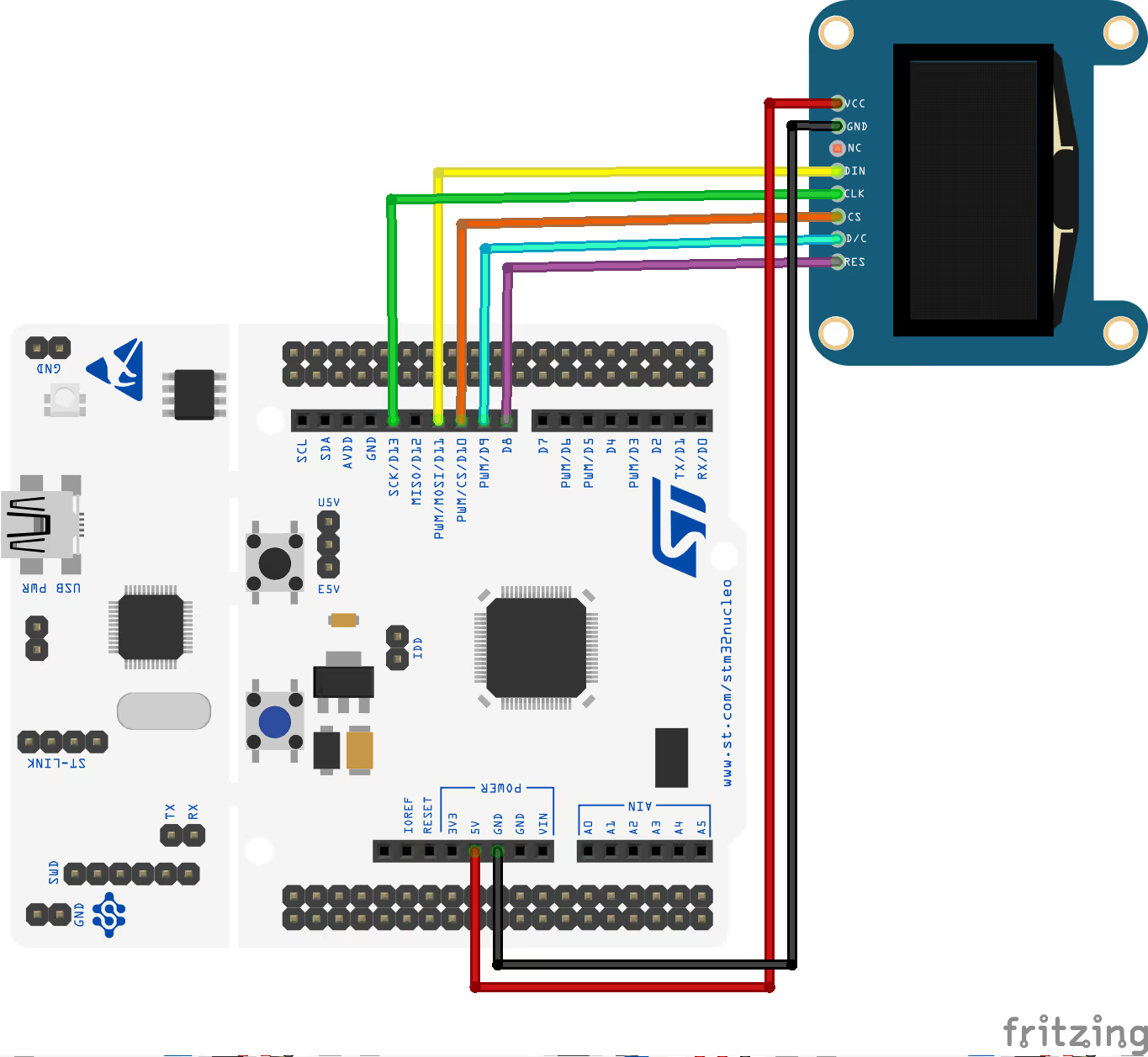
| SH1106 Pin | Function | STM32 Pin |
|---|---|---|
| VCC | Power Supply | 5 V |
| GND | Ground | GND |
| SCK | SPI Clock | PA5 |
| MOSI (SDI) | SPI Data | PA7 |
| RESET | Reset | PA9 |
| DC / RS | Data/Command Select | PC7 |
| CS | Chip Select | PB6 |
GPIO & Delay Callback (SPI)
uint8_t u8x8_gpio_and_delay(u8x8_t *u8x8, uint8_t msg,
                             uint8_t arg_int, void *arg_ptr)
{
    switch(msg)
    {
    case U8X8_MSG_DELAY_MILLI:
        HAL_Delay(arg_int);
        break;
    case U8X8_MSG_GPIO_CS:
        HAL_GPIO_WritePin(CS_GPIO_Port, CS_Pin, arg_int);
        break;
    case U8X8_MSG_GPIO_DC:
        HAL_GPIO_WritePin(DC_GPIO_Port, DC_Pin, arg_int);
        break;
    case U8X8_MSG_GPIO_RESET:
        HAL_GPIO_WritePin(RESET_GPIO_Port, RESET_Pin, arg_int);
        break;
    }
    return 1;
}The callback handles four messages for hardware SPI:
U8X8_MSG_DELAY_MILLI— passesarg_intmilliseconds toHAL_Delay().U8X8_MSG_GPIO_CS/DC/RESET— writesarg_int(1 = set, 0 = reset) to the respective GPIO pin usingHAL_GPIO_WritePin().
No nano-delay messages or SPI clock/data messages are needed here because the hardware SPI peripheral handles the actual bit-banging.
Communication Callback (Hardware SPI)
uint8_t u8x8_spi(u8x8_t *u8x8, uint8_t msg,
                 uint8_t arg_int, void *arg_ptr)
{
    switch(msg)
    {
    case U8X8_MSG_BYTE_SET_DC:
        HAL_GPIO_WritePin(DC_GPIO_Port, DC_Pin, arg_int);
        break;
    case U8X8_MSG_BYTE_SEND:
        HAL_SPI_Transmit(&hspi1, (uint8_t *)arg_ptr, arg_int, 1000);
        break;
    case U8X8_MSG_BYTE_START_TRANSFER:
        HAL_GPIO_WritePin(CS_GPIO_Port, CS_Pin, GPIO_PIN_RESET);
        break;
    case U8X8_MSG_BYTE_END_TRANSFER:
        HAL_GPIO_WritePin(CS_GPIO_Port, CS_Pin, GPIO_PIN_SET);
        break;
    }
    return 1;
}Message breakdown:
U8X8_MSG_BYTE_SET_DC— sets or clears the DC pin (command vs. data mode).U8X8_MSG_BYTE_START_TRANSFER— pulls CS LOW to select the display and begin a transaction.U8X8_MSG_BYTE_SEND— transmitsarg_intbytes fromarg_ptrviaHAL_SPI_Transmit().U8X8_MSG_BYTE_END_TRANSFER— pulls CS HIGH to deselect the display and end the transaction.
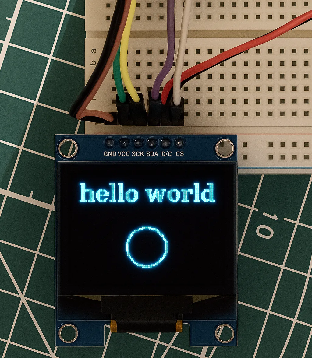
main() Setup & Result
#include "u8g2.h"
u8g2_t myDisplay;
int main(void)
{
// ... HAL_Init, SystemClock_Config, MX_SPI1_Init, MX_GPIO_Init ...
u8g2_Setup_sh1106_128x64_noname_f(&myDisplay, U8G2_R0,
u8x8_spi, u8x8_gpio_and_delay);
u8g2_InitDisplay(&myDisplay); // send init sequence; display sleeps after this
u8g2_SetPowerSave(&myDisplay, 0); // wake up the display
u8g2_ClearDisplay(&myDisplay);
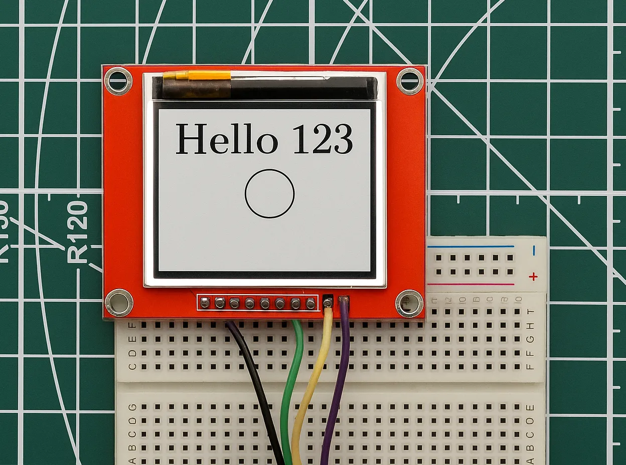
u8g2_SetFont(&myDisplay, u8g2_font_ncenB14_tr);
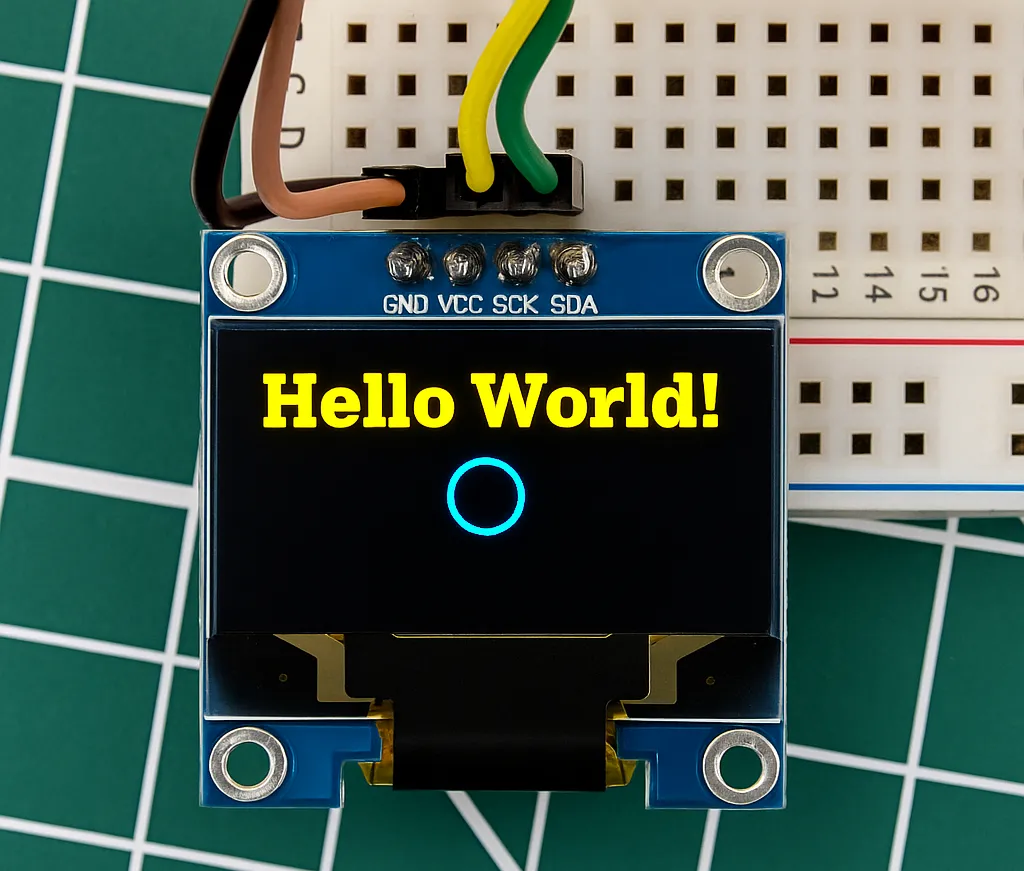
u8g2_DrawStr(&myDisplay, 0, 15, "Hello world");
u8g2_DrawCircle(&myDisplay, 60, 30, 10, U8G2_DRAW_ALL);
u8g2_SendBuffer(&myDisplay); // flush framebuffer to display
while (1) {}
}u8g2_Setup_sh1106_128x64_noname_f — the _f suffix selects full-buffer mode. U8G2_R0 is no rotation. After setup, u8g2_InitDisplay() sends the hardware init sequence and leaves the display in sleep mode; u8g2_SetPowerSave(&myDisplay, 0) wakes it. All drawing functions write to the in-RAM framebuffer. u8g2_SendBuffer() pushes the complete buffer to the display in one call.
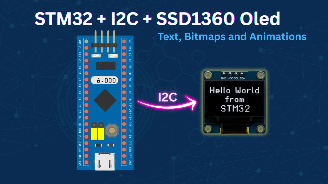
Hardware I2C — SSD1306 0.96″ OLED
CubeMX I2C Configuration
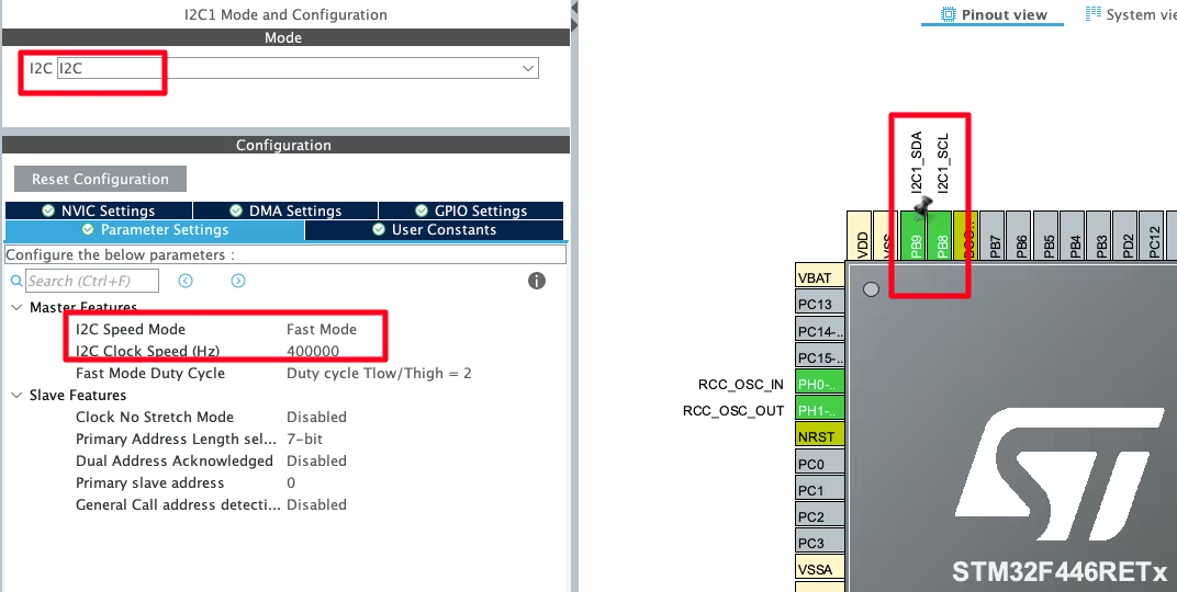
This example uses an STM32F446 Nucleo board. Enable I2C1 in CubeMX and configure:
- Mode: I2C
- Speed: Fast Mode — 400 kHz (required for the SSD1306)
- Pins: PB8 (SCL) and PB9 (SDA)
Note:
On the STM32F103, the default I2C1 pins are PB6 (SCL) and PB7 (SDA). Adjust to match your board.
Wiring — SSD1306 to STM32
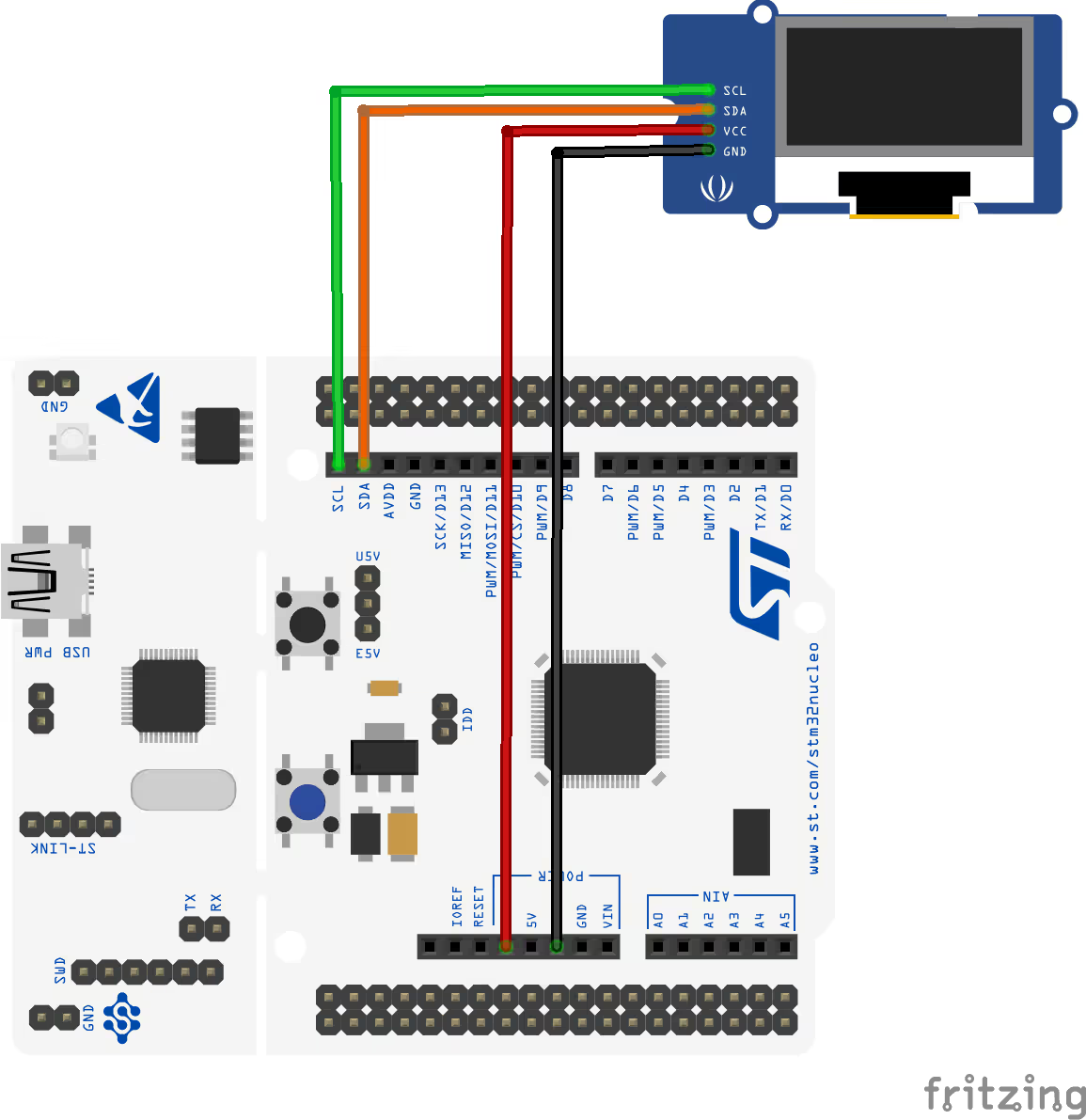
| SSD1306 Pin | Function | STM32 Pin |
|---|---|---|
| VCC | Power Supply | 3.3 V |
| GND | Ground | GND |
| SCL | I²C Clock | PB8 |
| SDA | I²C Data | PB9 |
GPIO & Delay Callback (I2C)
For I2C, there are no discrete CS, DC, or RESET pins to control. The GPIO callback only needs to handle delays:
uint8_t u8x8_gpio_and_delay(u8x8_t *u8x8, uint8_t msg,
                             uint8_t arg_int, void *arg_ptr)
{
    switch(msg)
    {
    case U8X8_MSG_DELAY_MILLI:
        HAL_Delay(arg_int);
        break;
    }
    return 1;
}All I2C signalling (start, stop, ACK) is handled internally by the hardware I2C peripheral and the communication callback below.
Communication Callback (Hardware I2C)
I2C data transfer uses a buffered pattern — U8G2 calls BYTE_SEND multiple times per transaction, so the data is accumulated in a local buffer and transmitted all at once on BYTE_END_TRANSFER:
uint8_t u8x8_i2c(u8x8_t *u8x8, uint8_t msg,
                 uint8_t arg_int, void *arg_ptr)
{
    static uint8_t buffer[32]; // U8G2 never sends more than 32 bytes per transfer
    static uint8_t buf_idx;
    uint8_t *data;

    switch(msg)
    {
    case U8X8_MSG_BYTE_SEND:
        data = (uint8_t *)arg_ptr;
        while (arg_int > 0) {
            buffer[buf_idx++] = *data;
            data++;
            arg_int--;
        }
        break;
    case U8X8_MSG_BYTE_START_TRANSFER:
        buf_idx = 0;            // reset buffer index for a new transaction
        break;
    case U8X8_MSG_BYTE_END_TRANSFER:
        HAL_I2C_Master_Transmit(&hi2c1, 0x78, buffer, buf_idx, 1000);
        break;
    default:
        return 0;
    }
    return 1;
}Message breakdown:
U8X8_MSG_BYTE_START_TRANSFER— resetsbuf_idxto 0, clearing the buffer for a new transaction.U8X8_MSG_BYTE_SEND— copies incoming bytes fromarg_ptrinto the local buffer.U8X8_MSG_BYTE_END_TRANSFER— transmits the complete buffer viaHAL_I2C_Master_Transmit(). The slave address0x78is the SSD1306’s 8-bit I2C address (7-bit address0x3Cshifted left by 1).
Address Note:
If your SSD1306 module uses address 0x3D (SA0 HIGH), change 0x78 to 0x7A in the transmit call.
main() Setup & Result
#include "u8g2.h"

u8g2_t myDisplay;

int main(void)
{
    // ... HAL_Init, SystemClock_Config, MX_I2C1_Init ...

    u8g2_Setup_ssd1306_i2c_128x64_noname_f(&myDisplay, U8G2_R0,
                                            u8x8_i2c, u8x8_gpio_and_delay);
    u8g2_InitDisplay(&myDisplay);
    u8g2_SetPowerSave(&myDisplay, 0);

    u8g2_ClearDisplay(&myDisplay);
    u8g2_SetFont(&myDisplay, u8g2_font_ncenB14_tr);
    u8g2_DrawStr(&myDisplay, 0, 15, "Hello world");
    u8g2_DrawCircle(&myDisplay, 60, 30, 10, U8G2_DRAW_ALL);
    u8g2_SendBuffer(&myDisplay);

    while (1) {}
}The only difference from the SPI example is the setup function name (u8g2_Setup_ssd1306_i2c_128x64_noname_f) and the communication callback (u8x8_i2c). Everything else — init, wake, draw, send — is identical.
Software SPI — HX1230 Graphic LCD
Why Software SPI for HX1230?
The HX1230 graphic LCD uses a 9-bit instruction format — 1 D/C bit followed by 8 data bits — for every byte it receives. STM32’s hardware SPI peripheral supports only 8-bit or 16-bit transfers, making 9-bit transmission cumbersome without careful bit-packing logic.
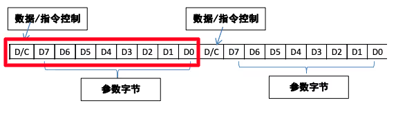
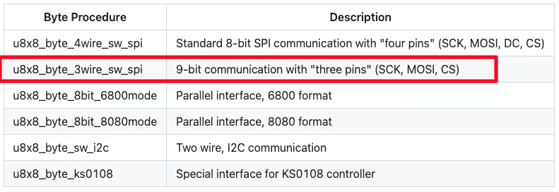
Software SPI (bit-banging) sidesteps this entirely. U8G2 provides a predefined u8x8_byte_3wire_sw_spi callback that handles the 9-bit protocol — you only need to implement the GPIO toggle logic in your u8x8_gpio_and_delay callback.
CubeMX GPIO Configuration
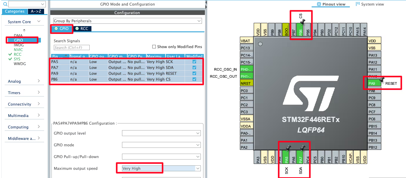
Since the hardware SPI peripheral is not used, configure all communication pins as GPIO Output:
| CubeIDE Label | Pin | Function |
|---|---|---|
| SCK | PA5 | Software SPI Clock |
| SDA | PA7 | Software SPI Data |
| RESET | PA9 | Display Reset |
| DC | PC7 | Data/Command Select |
| CS | PB6 | Chip Select |
In the GPIO Configuration panel, set the output speed for all five pins to Very High — this is required for software SPI to generate a clock fast enough for the display.
Wiring — HX1230 to STM32
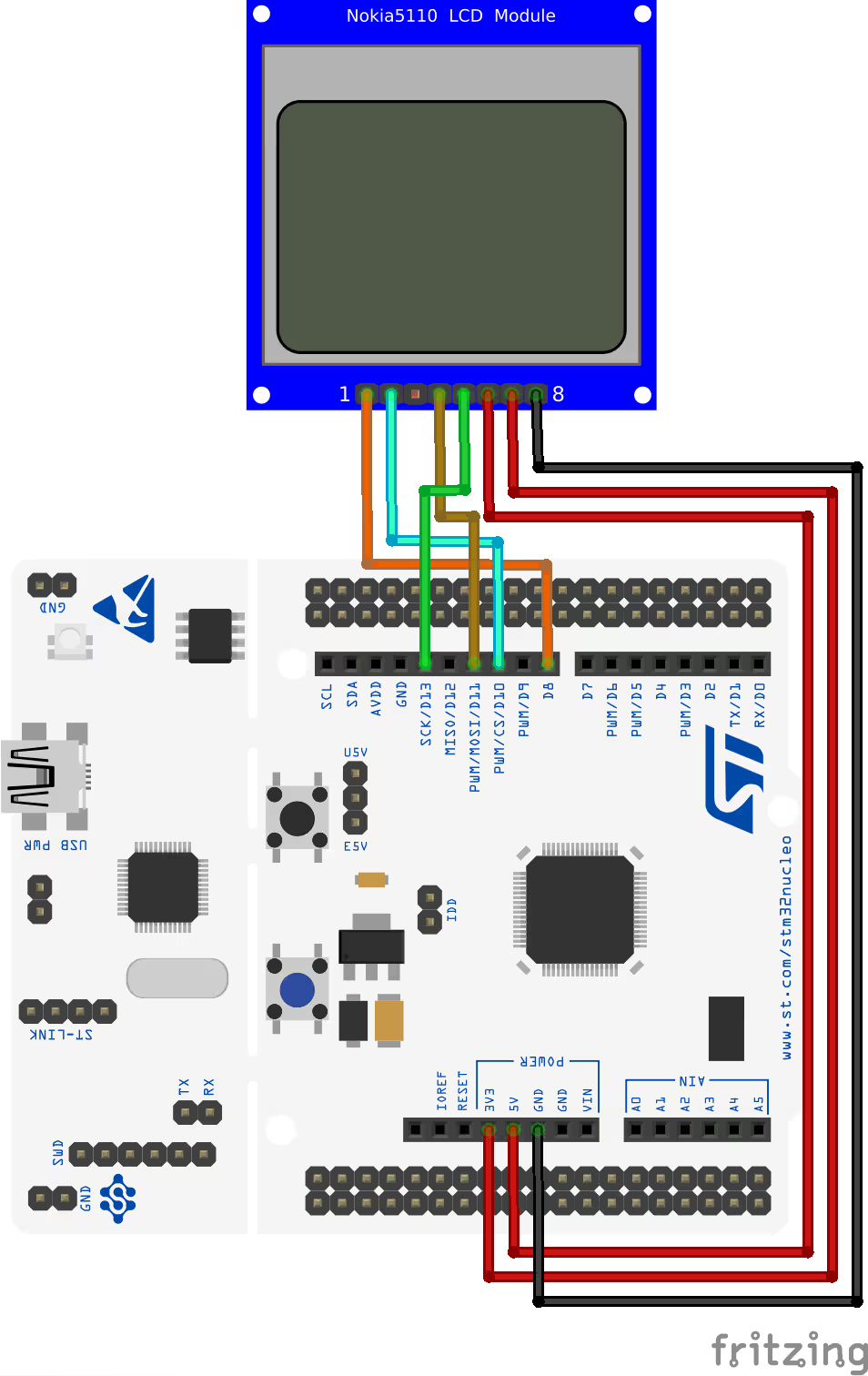
The physical connections follow the same pattern as a hardware SPI display. The HX1230 has no dedicated DC pin — the D/C bit is embedded in the 9-bit protocol and handled by U8G2’s software SPI callback internally. Leave DC unconnected on the display side.
| HX1230 Pin | Function | STM32 Pin |
|---|---|---|
| VCC | Power Supply | 3.3 V |
| GND | Ground | GND |
| SCK | SPI Clock | PA5 |
| SDA | SPI Data | PA7 |
| RESET | Reset | PA9 |
| CS | Chip Select | PB6 |
GPIO & Delay Callback (Software SPI)
Software SPI requires additional messages to manually toggle the clock and data pins, plus nanosecond-level delays to control the clock frequency:
uint8_t u8x8_gpio_and_delay(u8x8_t *u8x8, uint8_t msg,
                             uint8_t arg_int, void *arg_ptr)
{
    switch(msg)
    {
    case U8X8_MSG_DELAY_NANO:
        asm("NOP");           // ~1 ns at 72 MHz; enough for a fast software clock
        break;
    case U8X8_MSG_DELAY_100NANO:
        for (int i = 0; i < 30; i++) asm("NOP");
        break;
    case U8X8_MSG_DELAY_MILLI:
        HAL_Delay(arg_int);
        break;
    case U8X8_MSG_GPIO_SPI_DATA:
        HAL_GPIO_WritePin(SDA_GPIO_Port, SDA_Pin, arg_int);
        break;
    case U8X8_MSG_GPIO_SPI_CLOCK:
        HAL_GPIO_WritePin(SCK_GPIO_Port, SCK_Pin, arg_int);
        break;
    case U8X8_MSG_GPIO_CS:
        HAL_GPIO_WritePin(CS_GPIO_Port, CS_Pin, arg_int);
        break;
    case U8X8_MSG_GPIO_RESET:
        HAL_GPIO_WritePin(RESET_GPIO_Port, RESET_Pin, arg_int);
        break;
    }
    return 1;
}Additional messages compared to hardware SPI:
U8X8_MSG_DELAY_NANO— a singleNOPinstruction provides a sub-nanosecond pause sufficient to pace a soft SPI clock at 72 MHz.U8X8_MSG_DELAY_100NANO— 30NOPinstructions approximate a ~400 ns delay when needed.U8X8_MSG_GPIO_SPI_DATA/U8X8_MSG_GPIO_SPI_CLOCK— U8G2’s software SPI callback calls these to toggle the data and clock lines for each bit. Your job here is simply to callHAL_GPIO_WritePin()with the value ofarg_int.
main() Setup & Result
#include "u8g2.h"

u8g2_t myDisplay;

int main(void)
{
    // ... HAL_Init, SystemClock_Config, MX_GPIO_Init ...

    u8g2_Setup_hx1230_96x68_f(&myDisplay, U8G2_R0,
                               u8x8_byte_3wire_sw_spi, u8x8_gpio_and_delay);
    u8g2_InitDisplay(&myDisplay);
    u8g2_SetPowerSave(&myDisplay, 0);

    u8g2_ClearDisplay(&myDisplay);
    u8g2_SetFont(&myDisplay, u8g2_font_ncenB14_tr);
    u8g2_DrawStr(&myDisplay, 0, 15, "Hello world");
    u8g2_DrawCircle(&myDisplay, 60, 30, 10, U8G2_DRAW_ALL);
    u8g2_SendBuffer(&myDisplay);

    while (1) {}
}The key difference here is the byte communication parameter: instead of a custom callback, U8G2’s built-in u8x8_byte_3wire_sw_spi is passed directly. This predefined function handles the 9-bit D/C + 8-data-bit protocol for 3-wire software SPI displays like the HX1230. No custom byte callback is required.
Port U8G2 to STM32 — Video Tutorial
Watch the complete walkthrough: setting up the U8G2 library in CubeIDE, implementing GPIO/delay and communication callbacks, and running demos on the SH1106 (hardware SPI), SSD1306 (hardware I2C), and HX1230 (software SPI) — including an explanation of full-buffer vs. page-buffer rendering modes.
U8G2 on STM32: Frequently Asked Questions
Conclusion
U8G2's porting model is deliberately minimal — two callback functions is all that separates your STM32 from a graphics library with over 100 display drivers, a rich font system, and a full drawing API. Once you understand the callback message structure, switching from one display to another is a matter of changing the setup function name and adjusting the wiring.
The three examples here cover the most common patterns: hardware SPI for fast pixel-pushing displays like the SH1106, hardware I2C for the two-wire SSD1306 setup, and software SPI for displays with non-standard protocols like the HX1230. The same u8g2_ClearDisplay() / u8g2_DrawStr() / u8g2_SendBuffer() pattern works identically across all three.
For dedicated single-display drivers without a full graphics library, the SSD1306 I2C tutorial and SH1106 I2C tutorial cover lightweight HAL-based approaches. For full graphical UI frameworks on larger TFT displays, the LVGL on STM32 series and TouchGFX tutorials are the natural next step.
Download the complete CubeIDE project below — it includes all three display examples (SH1106 SPI, SSD1306 I2C, HX1230 software SPI) in a single STM32F446 project with the U8G2 csrc folder and all three main.c variants.
Download U8G2 STM32 Project Files (F446 — All 3 Displays)
Complete CubeIDE project for STM32F446 with U8G2 csrc library and three display examples: SH1106 hardware SPI, SSD1306 hardware I2C, and HX1230 software SPI. Free to download — support the work if it helped you.
Browse More STM32 Oled Tutorials


Guten Morgen Ich Ärgere mich mit einem SH1106 / I2c rum
welche Startsec benötigt der?
Die Beispiele Funktionieren alle….
I just used your ported u8g2 library code for SSD1306 0.9in OLED with my STM32F411CEU6 black pill module… It worked perfect!!! Thank you so much ControllersTech for such a clean work!!!.
I even tried changing the font to my fav fixed width font “u8g2_font_unifont_tr” and it worked!
If any one needs help for using the above code in STM32, you can contact me @+91 9491685146