
Home ▸ STM32 Tutorials ▸
Updated On: September 14, 2025
STM32 as I2C SLAVE || PART 7
This is the 7th tutorial in the STM32 I2C Slave series. In this tutorial we will go through some of the things in the I2C slave, that we skipped over throughout this series. We will cover some of the configuration settings like Clock Stretching, General Call Detection and the Dual Address mode. I am also attaching the error handling part at the end of this tutorial as I mentioned in the video. I have explained it in the previous tutorial, but anyway I will copy that part in this one too.
We will cover all three topic one by one. the configuration setting for the I2C slave is shown below.
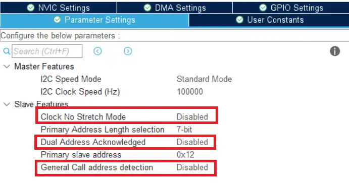
We haven’t talked about the highlighted parts in any of the tutorials yet. So let’s see them one by one.
VIDEO TUTORIAL
You can check the video to see the complete explanation and working of this project.
Clock Stretching
Clock stretching is a method by which any I2C device can slow down the i2C bus. The I2C clock speed is controlled by the master, but clock stretching allows all devices to slow down or even halt I2C communication.
We know that the I2C is a synchronous communication, so both the master and slave should be doing the same thing at the same time. For example, if the slave is sending the 4th bit of the data, then the master should also be looking for the 4th bit of the data.
There are some situations when the slave device can not keep up with the master. The device might be a little slow, or there might be some high priority interrupt it has to serve.
In these situations, clock stretching allows the slave device to hold the clock pin low for some additional time.
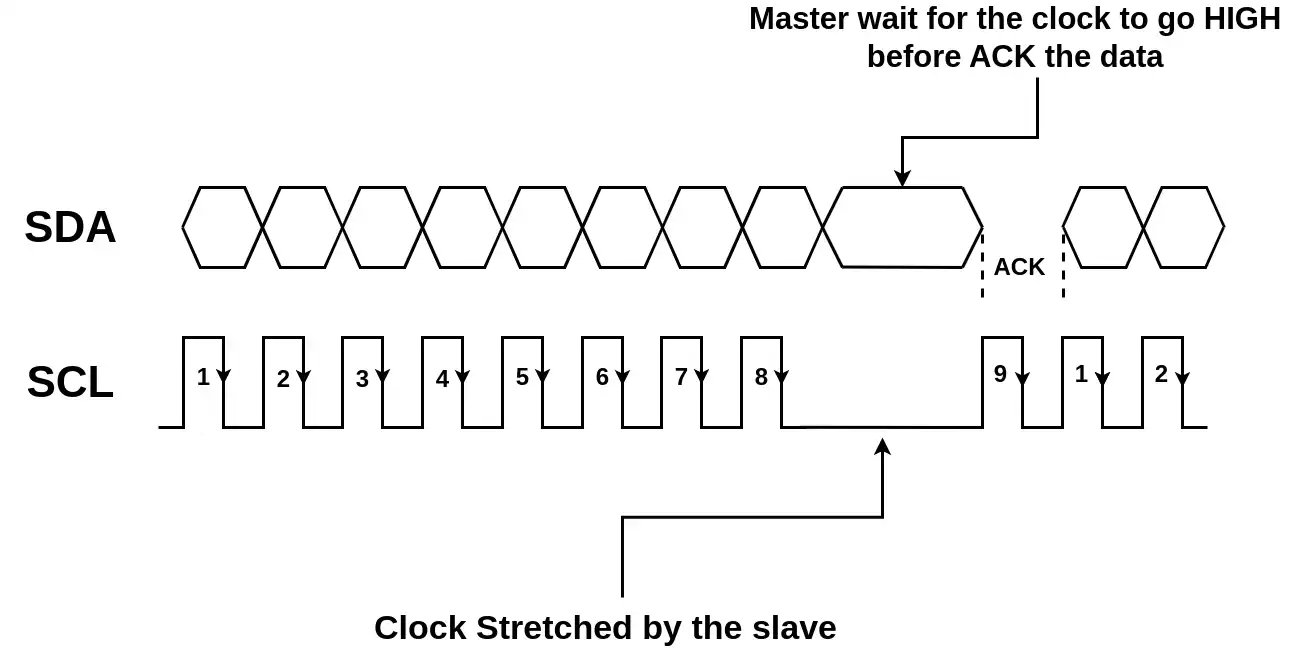
As you can see in the picture above, the slave stretches the clock and the master waits for the ACK. Once the clock is released by the slave, the master can read/send the ACK/NACK response.
Clock Stretching might reduce the total bandwidth of the shared bus. Especially for I2C buses shared by multiple devices, it is important to estimate the impacts of clock stretching. So do not make the slowest I2C device dominate the bus performance.
In the CubeMX Configuration, the option Clock No Stretch Mode is Disabled, so the Clock stretching is enabled. I don’t have means to show the test results for the clock stretching, so I will leave this part to theory itself.
General Address Call
The general call addresse for all devices on the I2C bus is 0. This address can be used by the master to communicate with all the slave devices on the bus. It’s up to the slave device whether to acknowledge this address or not.
The General call address can be used by the master to send some information to the slave. The master can not retrieve data using this Address.
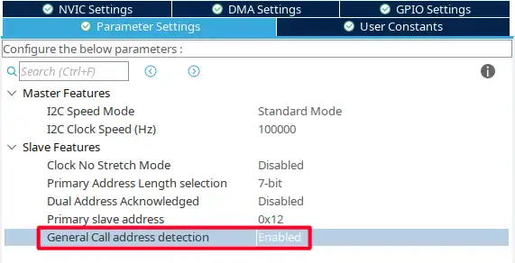
As shown in the image above, I have enabled the general call address detection. This will enable the slave to respond to the address 0.
The result is shown below.
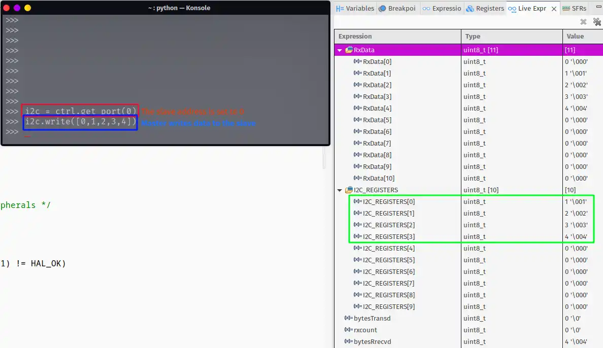
As shown in the image 1, the Master selects the address 0, and then write the data into the slave memory. The data get stored in the I2C REGISTERS.
The address 0 is the General call Address and the slave do respond to this address.
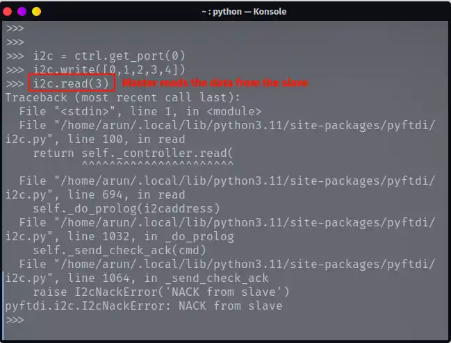
When the master tries to read data using the General call Address, it receives the NACK response from the slave. The General call address can only be used by the master to send some data (generally Instruction) to the slave.
Dual Address Acknowledgement
The dual address feature enables the STM32 as Slave to have 2 different I2C addresses. The device can respond to 2 different sets of addresses, each working independently.
We can even program the slave to perform different operations for requests received using the individual address.
Below is the configuration for the dual Address.
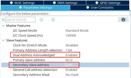
In the Image above, the Dual Address is enabled. The secondary 7 bit address is set to 0x45. Now the slave should be able to respond to both the addresses, 0x12 and 0x45.
We will see this in the images shown below.
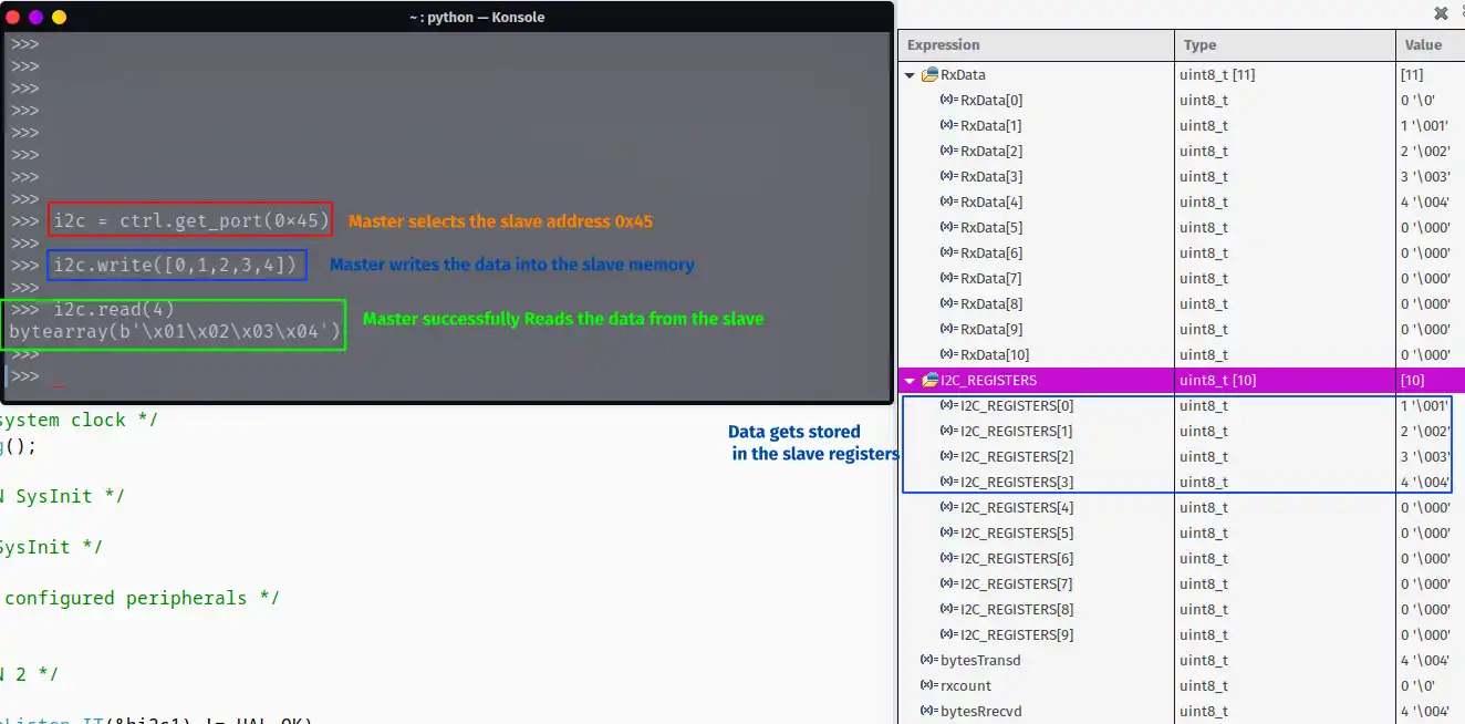
- As shown above, the master selects the address 0x45.
- When master writes the data to the slave, the slave accepts the data and the memory registers gets updated.
- The master can also read the data from the slave device.
Now we will change the slave address and see the result.
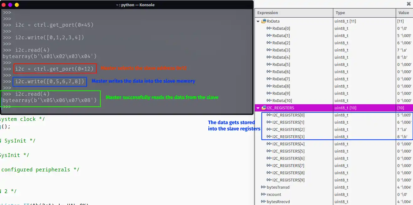
- As shown above, the master selects the address 0x12.
- The master can successfully perform the Read and Write operation with both the slave Addresses.
The slave respond to both the addresses. It’s like having 2 different slave devices on the bus. When the Address match callback is called for the slave, we can Read the Address Match Code variable to identify which address was called for this particular transfer.
void HAL_I2C_AddrCallback(I2C_HandleTypeDef *hi2c, uint8_t TransferDirection, uint16_t AddrMatchCode); The AddrMatchCode stores the address which called the Address Callback. We can store this address in a Global variable and then write separate tasks for each address match.
STM32 I2C Slave Tutorial Series

STM32 as I2C SLAVE || PART 2

STM32 as I2C SLAVE || PART 3

STM32 as I2C SLAVE || PART 4

STM32 as I2C SLAVE || PART 5

STM32 as I2C SLAVE || PART 6


This page is still linked a part 6 zip file. Can you please update to part 7 ?