Home ▸ STM32 Tutorials ▸
Updated On: June 20, 2026
How to Add LVGL to the FSMC LCD
This tutorial is the PART3 of the Interfacing the LCD via the FSMC peripheral. In the PART1 we covered how to connect the LCD via the FSMC, How to configure the FSMC and how to turn ON the display. In PART2 we covered how to add the touch interface to the LCD. Today we will see how to add the LVGL to this display and create UI using the squareline studio.
I am using the STM32F412 discovery development board. The LCD is already attached to this board and it is connected via the FSMC. The LCD uses the ST7789H2 controller and FT6X06 touch controller.
I have already covered the connection between the display and the MCU in the previous tutorials, so I will skip that part in this one. We will see how to include the LVGL to our previously created project.
VIDEO TUTORIAL
You can check the video to see the complete explanation and working of this project.
Add the LVGL Directory
We will download the LVGL version 8.3 from Github. The reason to use the older version is that we are going to use the Squareline Studio for the UI development and it still use the version 8.3 as the newest version.
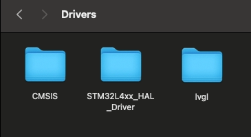
After extracting the folder from the zip, rename it to lvgl and copy in the STM32 Project Folder-> Drivers. This is shown below
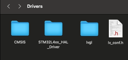
Now copy the lv_conf_template.h from inside the lvgl folder, paste it beside the lvgl folder and rename it to lv_conf.h. This is shown in the image below.
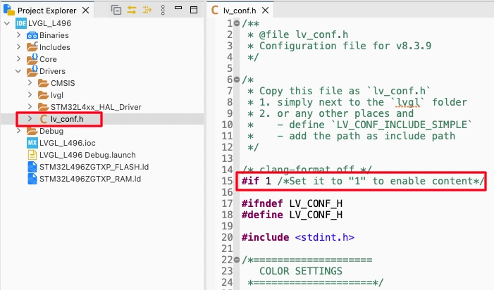
Now refresh the project in cube IDE and you will be able to locate the lv_conf.h in the Drivers directory. Open this file and change the #if 0 to #if 1 so to include the file in the project.
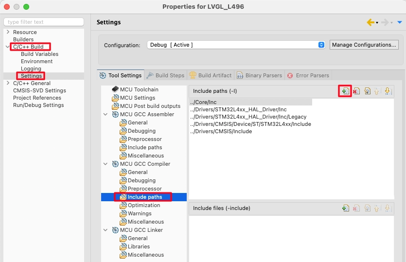
Right click on the project and open Properties.
open the c/c++ Build -> Settings -> MCU GCC Compiler -> Include Paths. Here click the add button to include the lvgl path to the project.
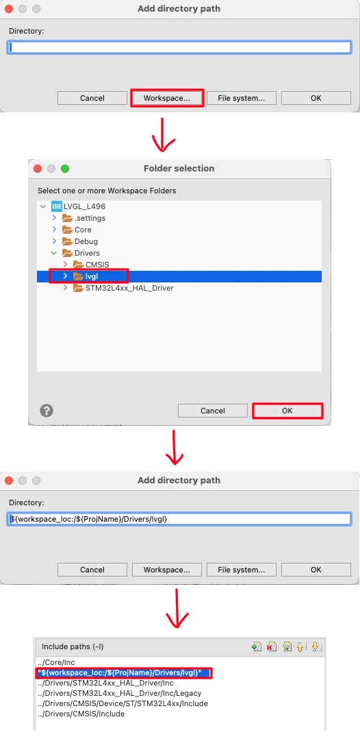
Select the Workspace in the pop up window, locate the lvgl folder we just added and click ok to add the path.
Connect Display driver to LVGL
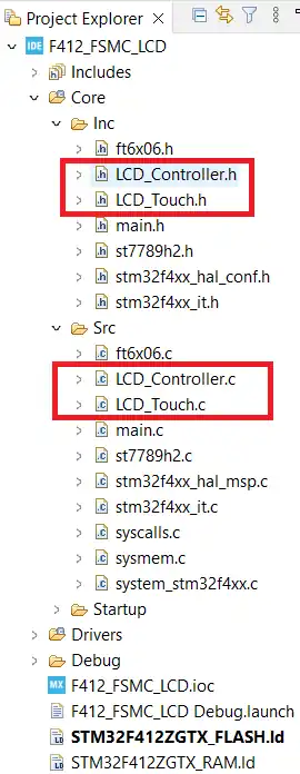
We already have the LCD library files inside the project folder. We have also created the files LCD_Controller files to connect the LCD driver to the MCU.
We will modify this file to connect the LCD driver to the LVGL also.
The display port template can be found at https://github.com/lvgl/lvgl/blob/release/v8.3/examples/porting/lv_port_disp_template.c. We can simply modify this template as per our need and availability of the MCU and the Display.
The lv_port_disp_init function is used to initialise the display and the display drivers for the LVGL.
void lv_port_disp_init(void)
{
disp_init();The first function inside it is the disp_init(), which is used to initialize the display. Here you need to call the initialization function for your display.
static void disp_init(void)
{
    ST7789H2_Init();
}In the ST7789H2 library I am using, the function ST7789H2_Init() is used to initialize it. That is why I am calling it inside the disp_init() function.
Next we will define and initialize the draw buffers for the display. You can use a single draw buffer or two draw buffers. Remember that the larger buffer you define, the more memory it is going to occupy. Hence you have to choose wisely between performance vs Space.
One Buffer
If only one buffer is used LVGL draws the content of the screen into that draw buffer and sends it to the display. LVGL then needs to wait until the content of the buffer is sent to the display before drawing something new in it. We can define it as follows:
    static lv_disp_draw_buf_t draw_buf_dsc_1;
    static lv_color_t buf_1[MY_DISP_HOR_RES * 10];                          /*A buffer for 10 rows*/
lv_disp_draw_buf_init(&draw_buf_dsc_1, buf_1, NULL, MY_DISP_HOR_RES * 10); /*Initialize the display buffer*/In the code above, we are defining a single buffer which can hold the data for 10 rows. This means that 10 rows will flush at a time on the display. We can simply send this data to the display by drawing one pixel at a time or by drawing bitmap.
Two Buffers
If two buffers are used LVGL can draw into one buffer while the content of the other buffer is sent to the display in the background. DMA or other hardware should be used to transfer data to the display so the MCU can continue drawing. This way, the rendering and refreshing of the display become parallel operations. We can define 2 buffers as follows:
    static lv_disp_draw_buf_t draw_buf_dsc_2;
    static lv_color_t buf_2_1[MY_DISP_HOR_RES * 10];                        /*A buffer for 10 rows*/
    static lv_color_t buf_2_2[MY_DISP_HOR_RES * 10];                        /*An other buffer for 10 rows*/
lv_disp_draw_buf_init(&draw_buf_dsc_2, buf_2_1, buf_2_2, MY_DISP_HOR_RES * 10); /*Initialize the display buffer*/In the code above, we are defining two buffers that can hold the data for 10 rows each. When one buffer is being flushed to the display using the DMA, the LVGL can update another buffer with new data.
After defining and initialising the buffers, we will setup the rest of the display driver’s parameters.
    lv_disp_drv_init(&disp_drv);                    /*Basic initialization*/

    disp_drv.hor_res = MY_DISP_HOR_RES;
    disp_drv.ver_res = MY_DISP_VER_RES;

    disp_drv.flush_cb = disp_flush;

    disp_drv.draw_buf = &draw_buf_dsc_2;

    lv_disp_drv_register(&disp_drv);
}- Here first of all we will initialise the display driver. Then set the display resolution, which is defined in the beginning of the file.
- The set the flush callback function, which will be called by the LVGL when it is ready to flush the content to the display. We will write this function later.
- Then set the draw buffer which we have defined above (either one buffer or 2 buffers).
- Finally register the display driver.
Now we will write the display flush function. This function is called by the LVGL when it is ready to flush the content to the display. This is the most important function of this file, as it contains the method to send the data to the display.
static void disp_flush(lv_disp_drv_t * disp_drv, const lv_area_t * area, lv_color_t * color_p)
{
  int16_t Height = area->y2 - area->y1 + 1;
  int16_t Width = area->x2 - area->x1 + 1;

  ST7789H2_SetDisplayWindow(area->x1, area->y1, Width, Height);
  ST7789H2_DrawRGBImage(area->x1, area->y1, Width, Height, (uint8_t*)color_p);
  lv_disp_flush_ready(disp_drv);
}- We will first calculate the height and width of the area that needs to be modified.
- Then call the function setwindow to set the region which needs to be modified.
- Then the DrawRGBImage function will be called to send the data to the area set in the above functions.
- Once the data has been transferred to the display, call the function lv_disp_flush_ready to inform the LVGL that we are ready for new transfer.
Connect Input drivers to LVGL
We already have the touch library files inside the project folder. We have also created the LCD_Touch files to connect the touch drivers to the MCU.
We will modify these files to connect these drivers to the LVGL also.
The LVGL provides the template for the Input device. The template can be found at https://github.com/lvgl/lvgl/blob/release/v8.3/examples/porting/lv_port_indev_template.c. We can simply modify this template as per our need and availability of the MCU and the Display.
The lv_port_indev_init function is used to initialize the input driver.
void lv_port_indev_init(void)
{
    static lv_indev_drv_t indev_drv;

touchpad_init();Inside this function we will first define the input device driver. Then touchpad_init() function initializes the touchpad. This is where we will initialize our touch driver. This is shown below.
/*Initialize your touchpad*/
static void touchpad_init(void)
{
    ft6x06_Init(0x70);
    ft6x06_TS_Start(0x70);
}I have the ft6x06 touch interface, so I am initializing it inside the touchpad_init() function. The function ft6x06_Init is used to initialize the touch interface. The touch interface is connected via the I2C, so it takes the device address as the parameter. We have already discussed in the previous tutorial that this address is 0x70.
After initializing the touch interface, we will call the function ft6x06_TS_Start to start the touch sensing.
Next we register the input device.
	/*Register a touchpad input device*/
	lv_indev_drv_init(&indev_drv);
	indev_drv.type = LV_INDEV_TYPE_POINTER;
	indev_drv.read_cb = touchpad_read;
	indev_touchpad = lv_indev_drv_register(&indev_drv);
}- Here first we will initialize the input driver.
- The driver type is set to pointer, since we are using a touchpad.
- The read callback is set to touchpad_read, this will be called by LVGL at a regular interval to read the touch input.
- Finally register the input device driver.
The touchpad read function shown below.
static void touchpad_read(lv_indev_drv_t * indev_drv, lv_indev_data_t * data)
{
    static lv_coord_t last_x = 0;
    static lv_coord_t last_y = 0;

    /*Save the pressed coordinates and the state*/
    if(touchpad_is_pressed()) {
        touchpad_get_xy(&last_x, &last_y);
        data->state = LV_INDEV_STATE_PR;
    }
    else {
        data->state = LV_INDEV_STATE_REL;<br>    }

    /*Set the last pressed coordinates*/
    data->point.x = last_x;
    data->point.y = last_y;
}- Here we will first check if the touch is pressed and valid, using the function touchpad_is_read.
- If the touch is valid, then the function touchpad_get_xy is used to read the touch coordinates and store them in the variables last_x and last_y
The function touchpad_is_pressed is used to validate the touch and the function touchpad_get_xy reads the touch coordinates. These are the main parts of the input driver, where you need to write the code according to your touch driver.
Below I have written the functions as according to the ft6x06.
 /*Return true is the touchpad is pressed*/
 static bool touchpad_is_pressed(void)
 {
     if (ft6x06_TS_DetectTouch(0x70))
     {
    	 return true;
     }

     return false;
}To detect the touch, we call the function ft6x06_TS_DetectTouch. This function returns 0 when no touch is detected and it returns either 1 or 2 based on how many touches are detected.
 static void touchpad_get_xy(lv_coord_t * x, lv_coord_t * y)
  {
     ft6x06_TS_GetXY(0x70, (uint16_t *)x, (uint16_t *)y);
}To read the touch coordinates we call the function ft6x06_TS_GetXY and pass the parameter from the main function itself.
Create Project using Squareline Studio
Open the studio, and create a new project.
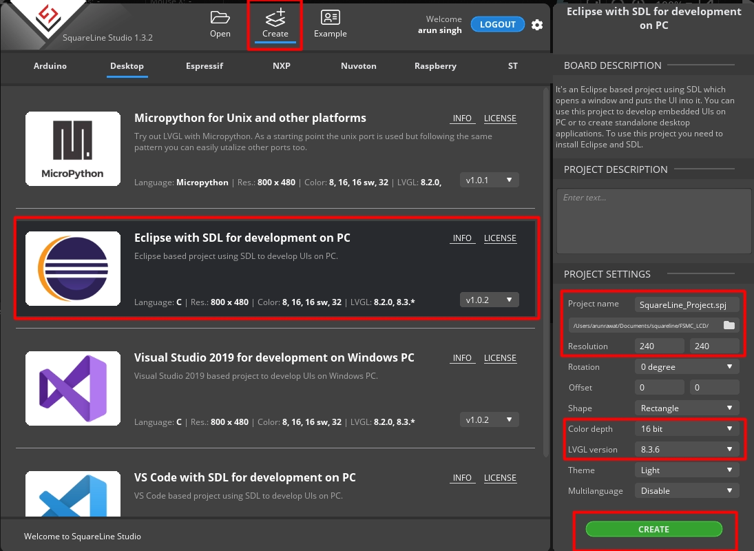
We will first generate the project for the Desktop environment, and then add it to the STM32 project.
- The Screen resolution is set to 240x240px
- Color depth is 16 bit.
- The LVGL version is 8.3.6, this should be same as what we download in the first tutorial.
- Click create to create the project.
Below is the UI design.
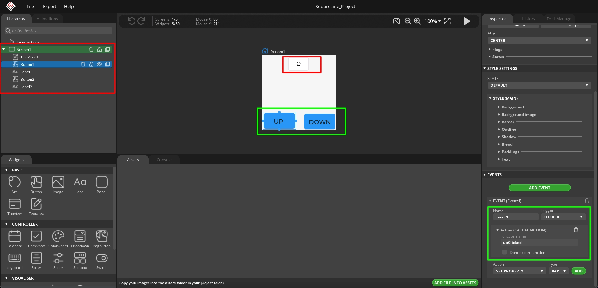
I have added a text area to display the counter. There are 2 buttons, UP and DOWN.
I have also added events for the buttons. The events will trigger when the buttons are clicked. When the UP button is clicked, the function upClicked will be called and when the DOWN button is clicked, the function downClicked will be called. We will write the code inside these function in the IDE itself.
After the design is complete, save the project and then open the project setting to update few things.

Here I have added the path for the UI file export. Also update the LVGL include path as shown in the image above.
After saving the project settings, we will export the UI files.
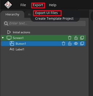
Click on Export, and then click Export UI Files. This will export the UI files in the path we set earlier. Below is the image showing the project folder.
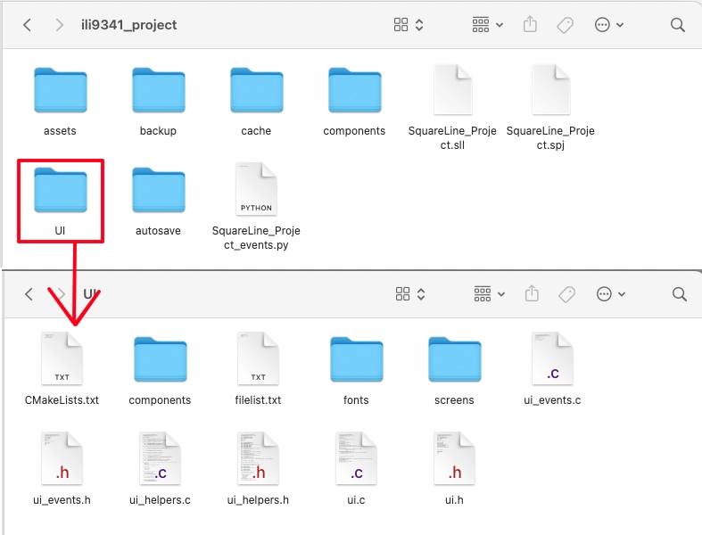
As you can see we have the UI files inside the project folder. This UI folder contains the files required by the LVGL to recreate the design on the display.
Add UI to the STM32 Project
Copy the UI folder we just exported to the STM32 Project -> Drivers. Once you refresh the project in the IDE, the folder should be visible.

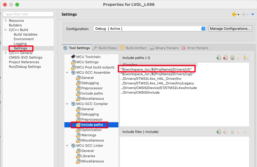
Right click on the project and open Properties.
open the c/c++ Build -> Settings -> MCU GCC Compiler -> Include Paths. Here click the add button to include the UI path to the project. This is same as how we added the LVGL to the path in the previous tutorial.
The main file
We need to add and initialize everything in the main file now.
#include "lvgl.h"
#include "LCD_Controller.h"
#include "LCD_Touch.h"
#include "ui.h"

int main()
{
  .....
  lv_init ();
  lv_port_disp_init();
  lv_port_indev_init();
  ui_init();
  while (1)
  {
	lv_timer_handler();
	HAL_Delay(5);
  }
} We first initialize the LVGL by calling the lv_init() function. The lv_port_disp_init() function is used to initialize the display and the function lv_port_indev_init() is used to initialize the touch driver. Finally we call the function ui_init() to initialize the UI we created in squareline studio.
Inside the while loop call the function lv_timer_handler() every 5ms. This is necessary for the LVGL to work.
We also need to modify the Interrupt file stm32f4xx_it.c.
void SysTick_Handler(void)
{
  lv_tick_inc(1);
  HAL_IncTick();
}Here inside the SysTick_Handler function we call the function lv_tick_inc(1). This is to keep track of the timer used by the LVGL.
While designing the UI, we created events for the buttons. When the buttons are clicked, the functions upClicked and downClicked are called. These functions are defined inside the UI->ui_event.c file. We will write some code which will execute on clicking the buttons.
int num = 0;
char numchar[4];

void upClicked(lv_event_t * e)
{
	num++;
	sprintf(numchar, "%d", num);
	lv_textarea_set_text(ui_TextArea1,numchar);
	memset (numchar, '\0', 4);<br> }

void downClicked(lv_event_t * e)
{
	num--;
	sprintf(numchar, "%d", num);
	lv_textarea_set_text(ui_TextArea1,numchar);
	memset (numchar, '\0', 4);
}Inside the ui_event.c file we first define a num integer and the numchar array to store the character equivalent of the num integer.
When the UP button is pressed, we will increment the num variable, then convert its value to the character equivalent and store it in the numchar array. Then send this value to the ui_TextArea. Finally clear the buffer so that there is no residue from the previous data.
Similarly, When the DOWN button is pressed, we will decrease the num variable, then convert its value to the character equivalent and store it in the numchar array. Then send this value to the ui_TextArea. Finally clear the buffer so that there is no residue from the previous data.
Result
Below is the gif showing the working.

You can see the counter is responding with respect to the button. Since we have defined the num as an integer variable, it can have the negative values also.
STM32 FSMC Tutorial Series
STM32 FMC || LCD PART2 || How to add touch interface to the LCD
STM32 FMC || LCD PART3 || Add LVGL & Create UI
LVGL on STM32 || PART 6

Subscribe
Login
0 Comments
Newest
