[vc_row width=”full”][vc_column width=”3/4″][vc_column_text]
STM32 USB MSC
In this tutorial we will cover how to use USB Mass Storage Class (MSC) in STM32. There will be two parts to this tutorial. In the first part we will allocate the RAM as the storage and read and write the data to this allocated portion. And in the second part, we will use the SD card as storage. SD card is connected via the SDIO interface.
Using RAM
We will use Embedded SRAM for this purpose. Check your device datasheet to know the size of the SRAM available for your device. I am using STM32F407ZE, and below is the picture from the device datasheet
According to the picture above, the 192 KB is divided between RAM and CCM. This means the actual RAM size is 192-64 = 128 KB. If you are using CUBEIDE for the project, you can see this detail in the memory region tab as shown below
You can see above that the RAM is 128 KB, and we will use some space from this RAM as the storage unit.
Let’s see the setup required in CUBE MX
CubeMX Setup
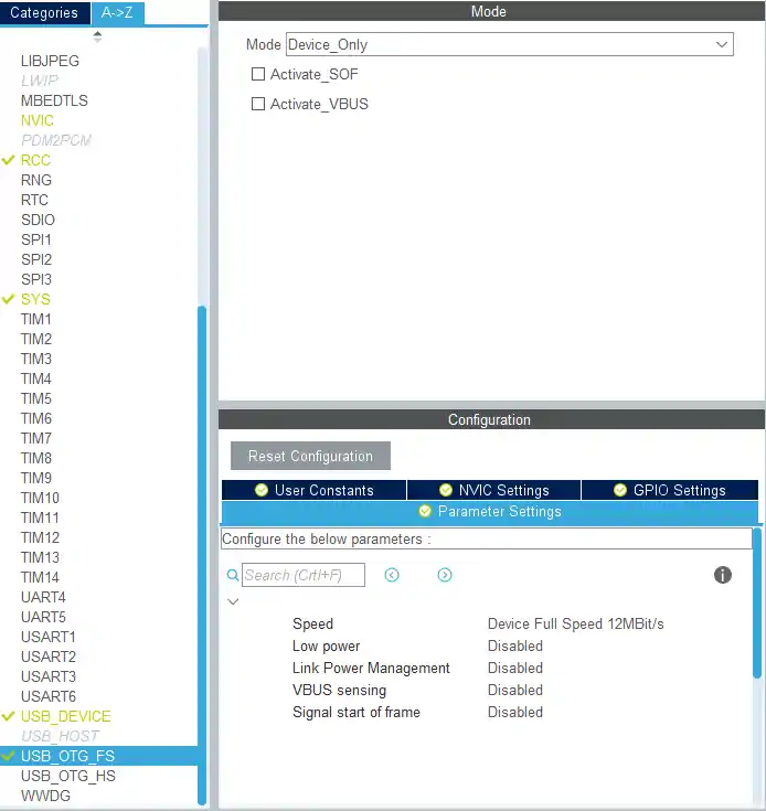
First of all, select the USB_OTG_FS and select the mode as Device_Only. Also note that the Speed is 12MBit/s
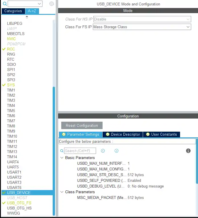
Next we need to select the USB_DEVICE and select the class as Mass Storage Class. Here you can modify the device descriptors, but i am leaving everything to default
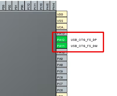
Two pins from the microcontroller got selected automatically for this purpose, as shown in the picture below
Some Insight into the code
We will make all the changes in the usbd_storage_if.c file. It is located at CORE -> USB_DEVICE -> App. Just open the file and modify as mentioned below
#define STORAGE_LUN_NBR                  1
#define STORAGE_BLK_NBR                  200  // enter twice the size of the RAM that you want to use
#define STORAGE_BLK_SIZ                  0x200
I have 123 KB of free RAM available, as you saw in the setup part. Out of this, I am going to use 100 KB of this RAM as the storage. That’s why I have entered 200 in the STORAGE_BLK_NBR. Rest is the default configuration. Block Size is 0x200, i.e. 512 Bytes.
uint8_t buffer[STORAGE_BLK_NBR*STORAGE_BLK_SIZ];Next, we need to define a buffer, which can hold the data. This buffer is of 100 KB in size, and the memory is used from the RAM obviously.
int8_t STORAGE_Read_FS(uint8_t lun, uint8_t *buf, uint32_t blk_addr, uint16_t blk_len)
{
  /* USER CODE BEGIN 6 */

  memcpy(buf, &buffer[blk_addr*STORAGE_BLK_SIZ], blk_len*STORAGE_BLK_SIZ);

  /* USER CODE END 6 */
}
In the STORAGE_Read_Fs we need to enter our function, which will copy the data from the buffer and save it in the function’s buf
int8_t STORAGE_Write_FS(uint8_t lun, uint8_t *buf, uint32_t blk_addr, uint16_t blk_len)
{
  /* USER CODE BEGIN 7 */

  memcpy(&buffer[blk_addr*STORAGE_BLK_SIZ], buf, blk_len*STORAGE_BLK_SIZ);

  /* USER CODE END 7 */
}
Similarly in the Write_Fs, the data will be copied from the function’s buf to our buffer.
Result
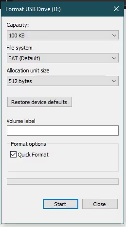
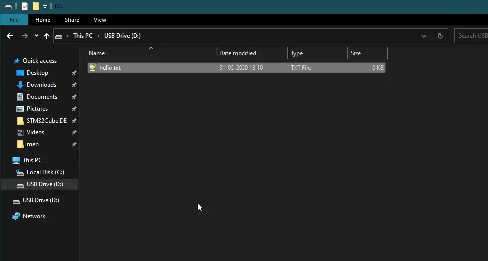
As you can see above, when the USB is connected, the device gets detected as the mass storage device of 100 KB size. we can create, copy, delete files and folders to or from the device.
You can check the video at the end to see the full setup and working
Using SD CARD
SD card will be used with the SDIO interface. The CubeMX setup for the USB remains same as shown earlier in this tutorial, but we need to add few more things to setup the SDIO for the SD CARD
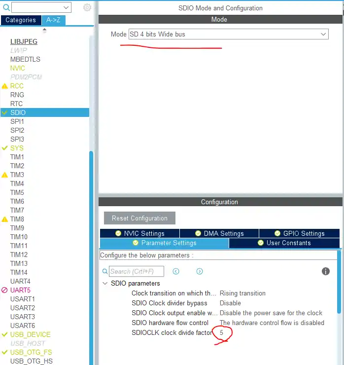
Setup have everything set to default except the SDIOCLK divide factor. How to set this is as follows
According to STM32F4 Timer Diagram, the SDIO/MMC clock is connected to APB2. In my clock Setup, the APB2 Peripheral clock is running at 84 MHz. Now all I have to do is to bring this clock to around 12 MHz. This is because the USB is also running at the same Frequency (check the USB Speed in USB_OTG_Fs).
The formula above is to set the value of Clock divide factor, and entering the value 5, will bring the SDIO_CK to 12 MHz, i.e. 84/ (5+2).
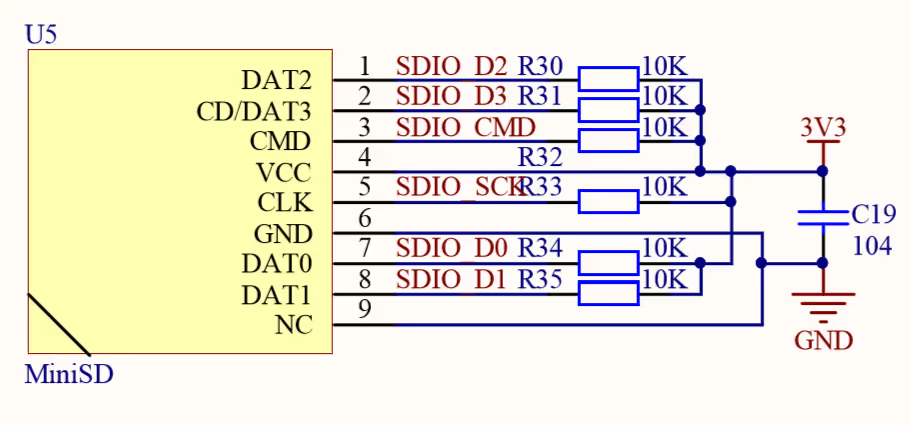
Below is the diagram of how the SDIO SD card module is connected to the board
Some insight into the code
We will make all the changes in the usbd_storage_if.c file. It is located at CORE -> USB_DEVICE -> App. Just open the file and modify as mentioned below
int8_t STORAGE_GetCapacity_FS(uint8_t lun, uint32_t *block_num, uint16_t *block_size)
{
  /* USER CODE BEGIN 3 */
  HAL_SD_CardInfoTypeDef info;
  int8_t ret = -1;

  HAL_SD_GetCardInfo(&hsd, &info);

  *block_num =  info.LogBlockNbr  - 1;
  *block_size = info.LogBlockSize;
  ret = 0;
  return ret;
  /* USER CODE END 3 */
}
The STORAGE_GetCapacity_Fs should be replaced with the code as mentioned above. This will basically get the capacity of the SD card
int8_t STORAGE_Read_FS(uint8_t lun, uint8_t *buf, uint32_t blk_addr, uint16_t blk_len)
{
  /* USER CODE BEGIN 6 */

   int8_t ret = -1;

  HAL_SD_ReadBlocks(&hsd, buf, blk_addr, blk_len, HAL_MAX_DELAY);

  /* Wait until SD card is ready to use for new operation */
  while (HAL_SD_GetCardState(&hsd) != HAL_SD_CARD_TRANSFER){}
  ret = 0;
  return ret;
  /* USER CODE END 6 */
}

/**
  * @brief  .
  * @param  lun: .
  * @retval USBD_OK if all operations are OK else USBD_FAIL
  */
int8_t STORAGE_Write_FS(uint8_t lun, uint8_t *buf, uint32_t blk_addr, uint16_t blk_len)
{
  /* USER CODE BEGIN 7 */
  int8_t ret = -1;

   HAL_SD_WriteBlocks(&hsd, buf, blk_addr, blk_len, HAL_MAX_DELAY);


  /* Wait until SD card is ready to use for new operation */
  while (HAL_SD_GetCardState(&hsd) != HAL_SD_CARD_TRANSFER){}
  ret = 0;
  return ret;
  /* USER CODE END 7 */
}
The Storage Read and Storage Write is also replaced wit the above code.
This is it for the modifications. We don’t need to do anything with the main.c file. Just upload the code and run it
Result
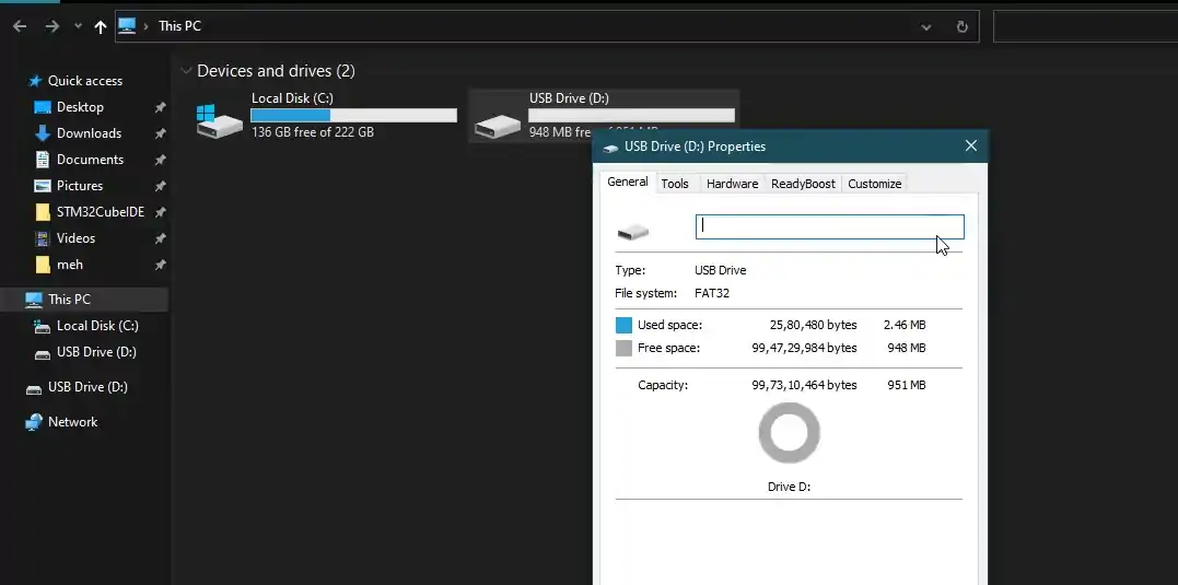
When the USB is connected, the card gets detected, which is of 1 GB in size. We can perform all types of operations here.
The speed for write and read is very slow at the moment.
Check out the Video Below
Info
You can help with the development by DONATING Below.
To download the project, click the DOWNLOAD button.
[/vc_column_text][/vc_column][vc_column width=”1/4″ offset=”vc_hidden-sm vc_hidden-xs”][vc_column_text]
[/vc_column_text][/vc_column][/vc_row]








Hi. Have you any tutorial about a composite usb device (CDC+MSC) ??
I would appreciate it very much.
Thank’s a lot.
Hello Sir,
I have been learning a lot from you, and I appreciate your excellent instructional skills. I am currently working on a project that involves integrating USB functionality for data transfer and data logging on an STM32F407VG microcontroller. Specifically, I want to log data files on an SD card and enable the user to download these logged files from the SD card via USB. Additionally, I’d like to allow users to copy files from their PC to the SD card via USB, all through the STM32F407VG using the SDIO communication protocol.
I’m facing a challenge in making the USB_OTG_FS (On-The-Go Full-Speed USB) and the SD card (using FatFS) work together seamlessly. I would greatly appreciate your guidance and any insights you might have on how to achieve this integration.
Here are some specific questions I have:
How do I configure USB_OTG_FS as a USB Device in STM32CubeMX or other development tools?
What are the essential initialization and setup steps for using the USB_OTG_FS as a USB Device alongside the FatFS library for SD card communication?
Are there any sample code snippets or project examples that demonstrate this integration?
What should I be mindful of when managing the data transfer between the USB and SD card to avoid conflicts or data corruption?
When selecting the SD card in FATFS in CubeMX, USB functionality is not working, but it works when we select “User-defined.” Please let me know about the use of the “User-defined” option in FATFS and why it is used. How is it used?
I would greatly appreciate any help from you, and I will be very grateful if you can assist me.
Hello.
Thank you for good example. It works however I have one issue. When USB storage is detected by Windows and I am checking files then some of them are missing. This is very random and each time device is inserted into USB then another files are missing. Meanwhile if device is running under Keil debug mode everything works fine, all files are visible every time. Could you please advise where could be the issue? Thank you.
Thank you. Very well presented.
I am using SD card and when USB is connected to PC it tries to format but fails “Windows is unable to format”. I will donate ($’s) if I get this resolved.
Have you got that issue fixed?
I’m getting a “Windows was unable to complete the format.” message. I’m following RAM tutorial. Tried on STM32F103 and on STM32F411, both same message. Any ideas?
Same issue here, while doing with SD card. Let me know if you get that fixed.
Ensure your “disk” is appropriate size. A RAMDisk 16KB(32*512) failed with same message, but 40KB(80*512) worked in my tests on L476. I didn’t try SD Card but may be similar issue.
I need to send any file from within that same storage via serial to another place, can you help me?
Hi Dear master, thank you for your video.
In both state FS and HS the Write speed is limited to 355 KB/s.
could you help me what is the problem?
Hi everyone, I have a question about how to set the frequency of 48 Mhz that is necessary for the MSC to work.
I cannot set a frequency of 48 Mhz because I do not have an external oscillator. What frequency would be the most appropriate? Currently I have set a frequency of 45 Mhz but I do not know if this frequency would be correct.
If you could guide me on what frequencies it could work or if it is not feasible for it to work at a frequency other than 48 Mhz. Thank you very much.
48 MHz is necessary.
Thank you very much. Now I can sleep
This line in not correct:
while (HAL_SD_GetCardState(&hsd) != HAL_SD_CARD_TRANSFER){}correct form:
while (HAL_SD_GetCardState(&hsd) == HAL_SD_CARD_TRANSFER){}or:
while (HAL_SD_GetCardState(&hsd) != HAL_SD_CARD_READY){}I tested, your variant doesn’t works
You have good instructor. Keep doing this videos and articles. I was learning too many things from you. Thanks..
and use DMA
Thanks.. Will try
for hi speed,you can setup the USB_DEVICE Parameter like this,thank you for your video
Hi, where did you find this parameter in USB_DEVICE. I couldn’t find