Home ▸ STM32 Tutorials ▸
Updated On: March 23, 2026
How to Load LVGL from Ext Flash Memory
In the previous tutorial we saw how to load the Assets (Images in the tutorial) from the external Flash. This Idea works fine if your MCU has low flash memory such that it won’t be able to accumulate all those images or fonts. But if the MCU has a very small internal flash (<200KB), then you can’t even load the LVGL in it.
I know according to LVGL docs the minimum Flash required is 64KB, but you would have to compromise a lot of things to make it work with this much flash. I have the STM32H750VBT6 based custom board. The MCU has the internal memory of 128KB but the board has W25Q64 connected in the QSPI mode.
So today in this tutorial we will see how to run the LVGL project from the external flash. We will use the famous XIP (Execute In Place) to run the application from external flash.
VIDEO TUTORIAL
You can check the video to see the complete explanation and working of this project.
Prerequisites
I am not going to cover everything in detail so you must be familiar with the following.
- How to Interface the W25Q using QSPI in H750 MCU and How to create an External Loader.
- How to boot the Application from External Flash in H750 MCU and W25Q chipset.
- Getting started with LVGL on STM32 MCUs.
Connection
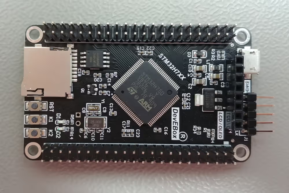
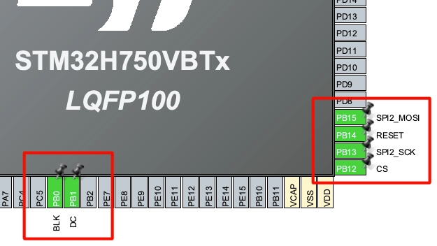
am using the STM32H750 custom development board and it has the W25Q64 flash memory soldered on it. You can see the image of the board shown below.
The board also has the header for connecting the TFT/Oled displays. Below is the pinout of the TFT/Oled Header.
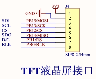
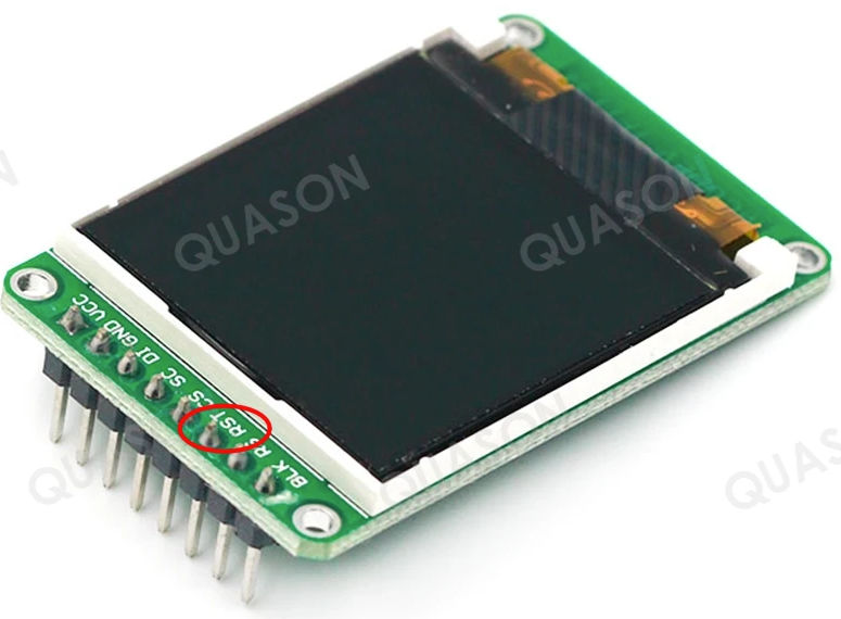
The display I have connected has the same pin order as above. But instead of the SDO pin, it has the Reset pin. This is fine as we are not expecting any output from the display.
CubeMX Configuration
The LCD is connected via the SPI. The configuration for the same is shown below.
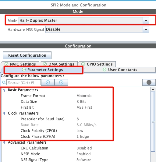
- I have enabled the SPI2 in Half Duplex mode because the display anyway does not have the SDO pin. The SPI is configured with 8 bits Data size.
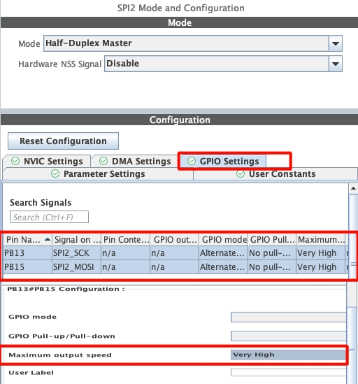
- The SPI pins should be configured with maximum output speed.
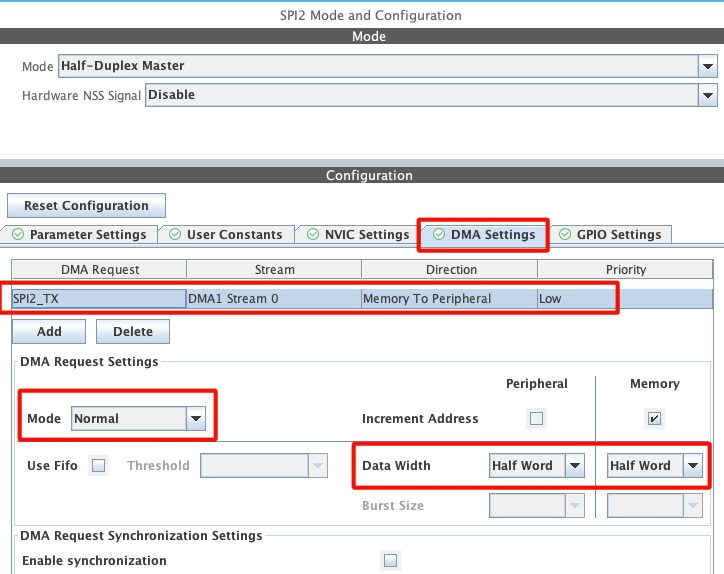
- Also enable the DMA for SPI TX. The DMA should be in the Normal Mode an the Data width should be Half Word (16 bits).
I know that the SPI is configured with 8 data bits whereas the DMA is configured with 16 data bits. This is because the library we will use, is going to switch the SPI to 16 bit mode before transferring the data via the DMA.
Below is the image showing the pin configuration in the cubeMX.
The pins above are configured as per the schematic of the board. I have also renamed the pins as per their functions. All the pins should be configured with the maximum output speed as shown below.
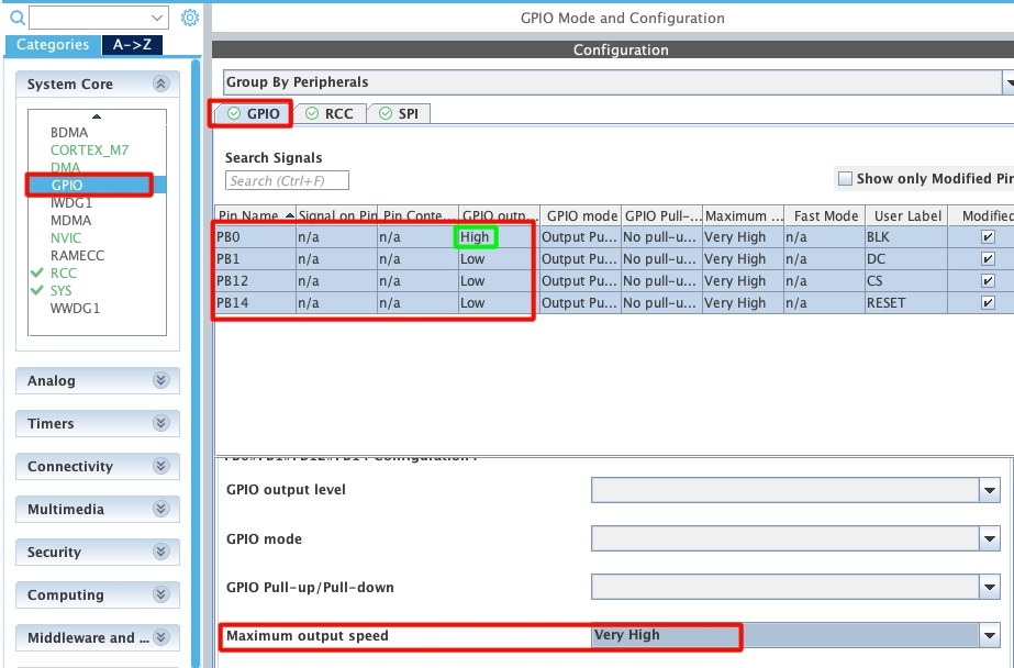
Note that the pin PB0 is connected to the backlight so it must be set HIGH.
Since we are going to store the project in the external flash, we need to configure the MPU also. The MPU configuration is shown below.
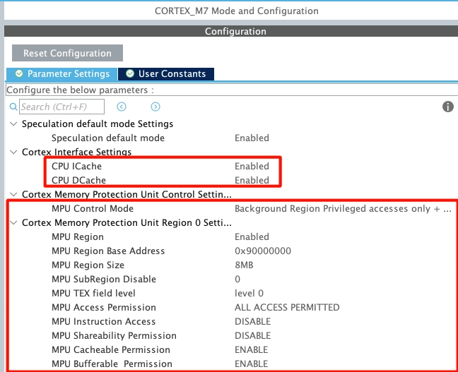
I have enabled both DCache and ICache. Enabling the cache is important as it improves the system performance by a significant amount.
The MPU is configured in the DEFAULT MODE.
- The Base Address for the first Region is set to 0x90000000 (QSPI address) with the region size of 8MB (The Memory Size).
- All access are permitted in this region with instruction access being disabled.
- The region is set as cacheable and bufferable, but not shareable.
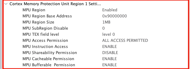
- We define another region of 1MB inside the first one, with the same start address 0x90000000.
- All access are permitted in this region with instruction access being Enabled.
- The region is set as cacheable and bufferable, but not shareable.
Additional Configuration
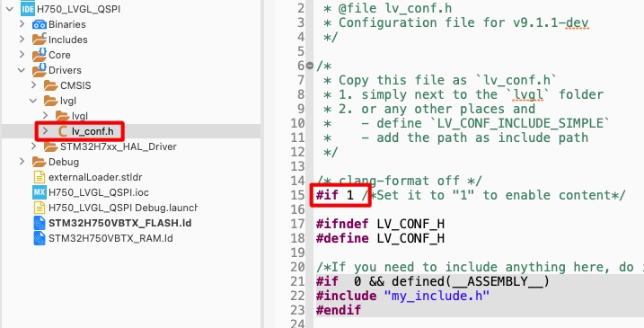
Download the latest LVGL from their Github. After extracting the folder from the zip, rename it to lvgl and copy in the STM32 Project Folder-> Drivers ->lvgl directory. You need to create the lvgl folder inside the Drivers folder and then copy the lvgl directory inside this folder. This is shown below.
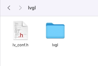
Also copy the lv_conf_template.h from inside the lvgl folder, paste it beside the lvgl folder and rename it to lv_conf.h. Open this file and change the #if 0 to #if 1 so to include the file in the project.
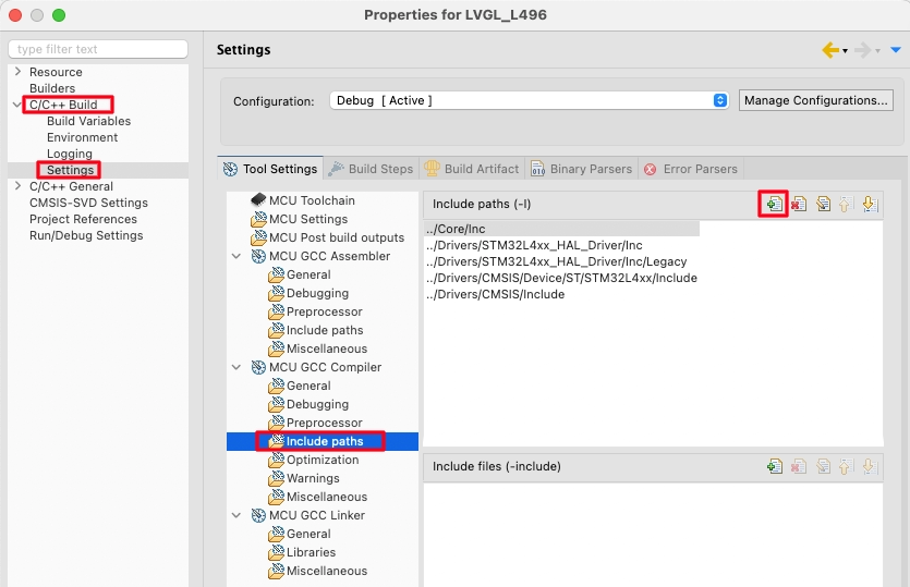
Right click on the project and open Properties.
open the c/c++ Build -> Settings -> MCU GCC Compiler -> Include Paths. Here click the add button to include the lvgl path to the project.
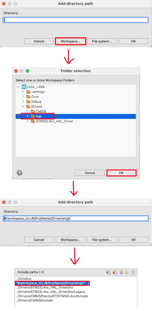
Select the Workspace in the pop up window, locate the lvgl folder we just added and click ok to add the path.
Open the ****_FLASH.ld file and modify the FLASH area as shown below.
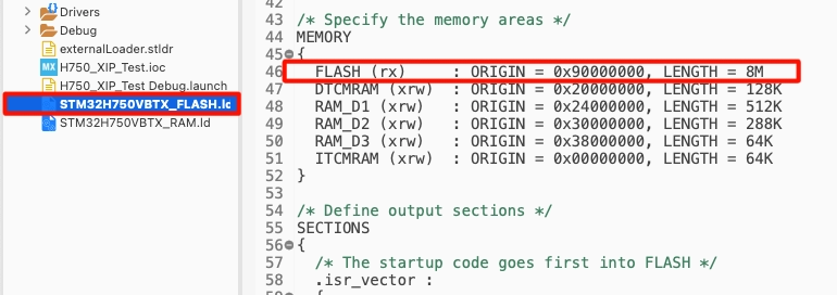
Here we will relocate the FLASH to QSPI (0x90000000) with the size equals to 8MB.
Now open the System_stm32H7xx.c file. Scroll down to SystemInit() function, and add the following at the end of the file.
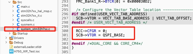
Here we will first reset the configuration register and then set the Vector Table Offset Register to the QSPI Address (0x90000000), this is where our FLASH is located n
The Code
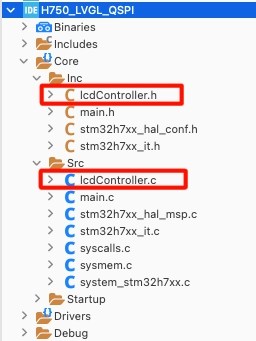
Let’s create a new source and header file for the display drivers. I have named them lcdController.c and lcdController.h.
In the new library LVGL has released a templet for STM32 display port. You can access the template at https://github.com/lvgl/lvgl/blob/master/examples/porting/lv_port_lcd_stm32_template.c
The new LVGL library already has the necessary drivers required to interface the LCD displays. Although the drivers are limited for few controllers but they are the ones which are used very common. Below is the image showing the display drivers included in the LVGL by default.
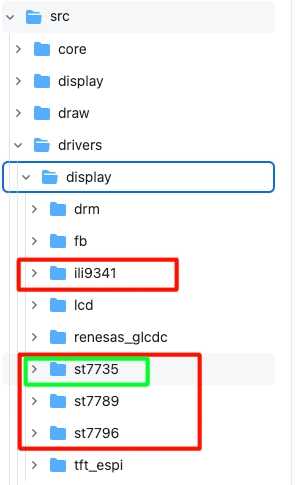
You can see above, the library already includes the drivers for ILI9341, ST7735, ST7789 and ST7796. If you have either of these LCD controllers, you can directly use the driver from here. The display I am using has the ST7735 controller, so I will use the same from here.
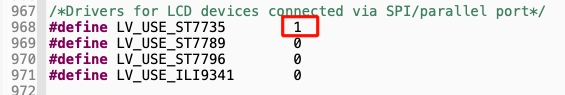
To use either of these drivers, you need to enable them in the lv_conf.h file as shown below.
Now copy the content from lv_port_lcd_stm32_template.c to lcdController.c and lv_port_lcd_stm32_template.h to lcdController.h.
After copying the content, we need to make some changes as per our configuration. They are as follows.
1. Change the default inclusion as shown below
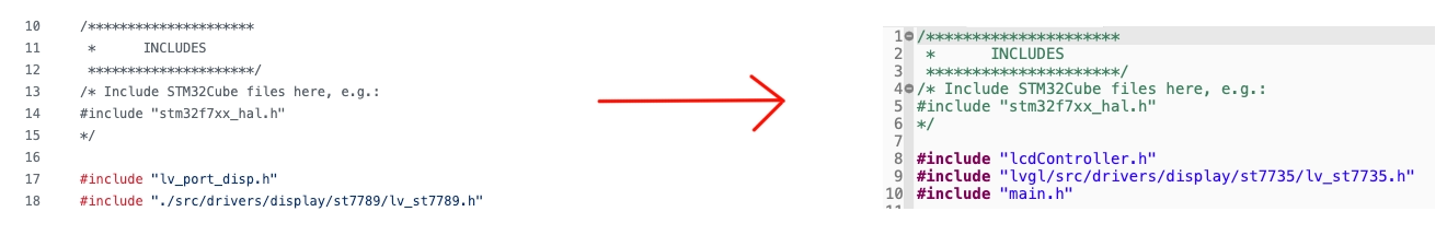
2. Define the display Resolution and the SPI TypeDef
#define MY_DISP_HOR_RES    128
#define MY_DISP_VER_RES    128

extern SPI_HandleTypeDef hspi2;The display resolution is 128×128 px. Also I am using SPI2, so it has been defines ad the external variable. The main handler is defined in the main.c file.
3. Modify the lv_port_disp_init function
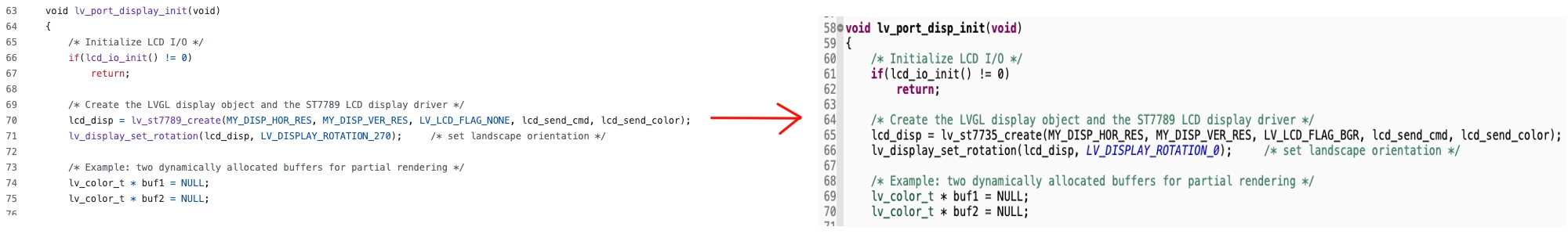
The display port template uses the st7789 library, hence the functions are used according to that. We will change it to st7735_create. Also the LV_LCD_FLAG_NONE in the function’s parameter has been changed to LV_LCD_FLAG_BGR. This is because the display I am using has the colours switched (Red and Blue). That is why the colour system has been changed from RGB to BGR.
4. Modify the lcd_io_init function
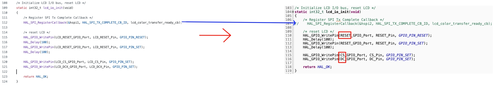
The function HAL_SPI_RegisterCallback is used to register custom callback for when the data transfer is completed. We will comment out this function because we will use the default HAL_SPI_TxCompleteCallback itself.
The pin names we defined in the cubeMX are different than what are being used in the library. So change the pin names everywhere in the library.
5. Modify the lcd_send_cmd function
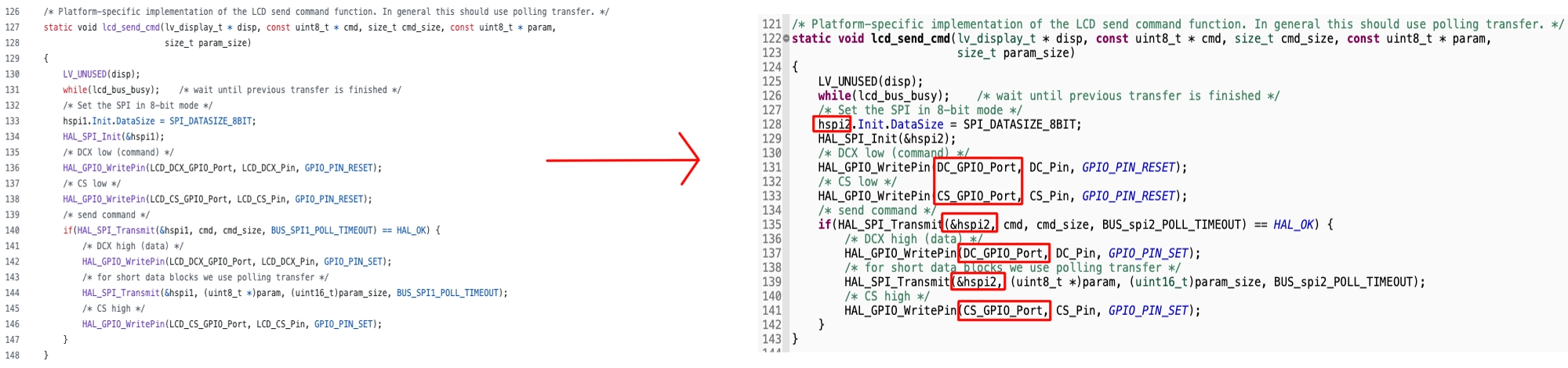
Here we will just change the names of the pins as we configured them in cubeMX. Also change the spi1 to spi2.
6. Modify the lcd_send_color function
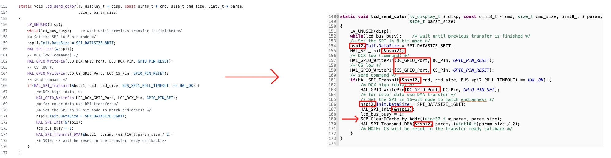
Here we will also change the names of the pins as we configured them in cubeMX and change the spi1 to spi2.
You can see above that SPI is switched to 16 bit data mode before the color data is actually transferred via the DMA. We have already configured the DMA in 16 bit mode, so this is fine. We have enabled the DCache in our project and that is why the Cache coherency issue will takes place when the data is transferred via the DMA. To prevent it, we are calling the function SCB_CleanDCache_by_Addr to clean the data cache.
7. Modify the callback function
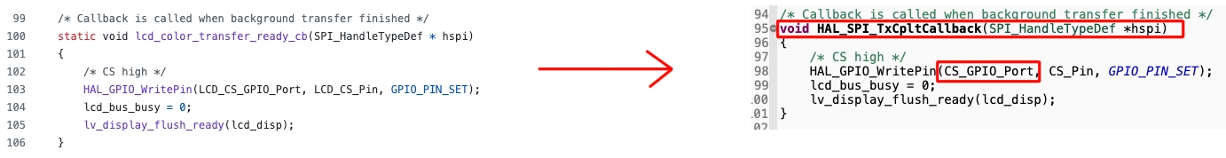
Here we will change the name of the callback to the default HAL_SPI_TxCpltCallback. This is called when the DMA finishes the data transfer. Inside this callback we are informing the LVGL that it is ready for the next color flush.
The main file
pen the interrupt source file (stm32h7xx_it.c) and add the following in the systick handler.
#include "lvgl/lvgl.h"  // To be added
.....
void SysTick_Handler(void)
{
  /* USER CODE BEGIN SysTick_IRQn 0 */
	lv_tick_inc(1);  // To be added
  /* USER CODE END SysTick_IRQn 0 */
  HAL_IncTick();
  /* USER CODE BEGIN SysTick_IRQn 1 */

  /* USER CODE END SysTick_IRQn 1 */
}Here we will first include the lvgl.h and then add the lv_tick_inc(1) inside the systick handler.
Next add the LVGL timer handler in the while loop.
  while (1)
  {
    /* USER CODE END WHILE */

    /* USER CODE BEGIN 3 */
	  lv_timer_handler();  // to be added
	  HAL_Delay(5);  // to be added
}This finishes the integration of LVGL with the STM32 controller. Now we will run some test code to see if the display shows some output.
In the main function, initialise the library and the display driver.
lv_init(); //Initialise LVGL UI library
lv_port_disp_init(); // intializse the display driversNow we will add a test code in the main function itself.
    /*Change the active screen's background color*/
    lv_obj_set_style_bg_color(lv_screen_active(), lv_color_hex(0x0000ff), LV_PART_MAIN);  // Blue

    /*Create a white label, set its text and align it to the center*/
    lv_obj_t * label = lv_label_create(lv_screen_active());
    lv_label_set_text(label, "Hello world");
    lv_obj_set_style_text_color(lv_screen_active(), lv_color_hex(0xffffff), LV_PART_MAIN);
lv_obj_align(label, LV_ALIGN_CENTER, 0, 0);The above code sets the background color to Blue. Then it creates a white label “Hello world”.
Result
Below is the image showing the output on the display.
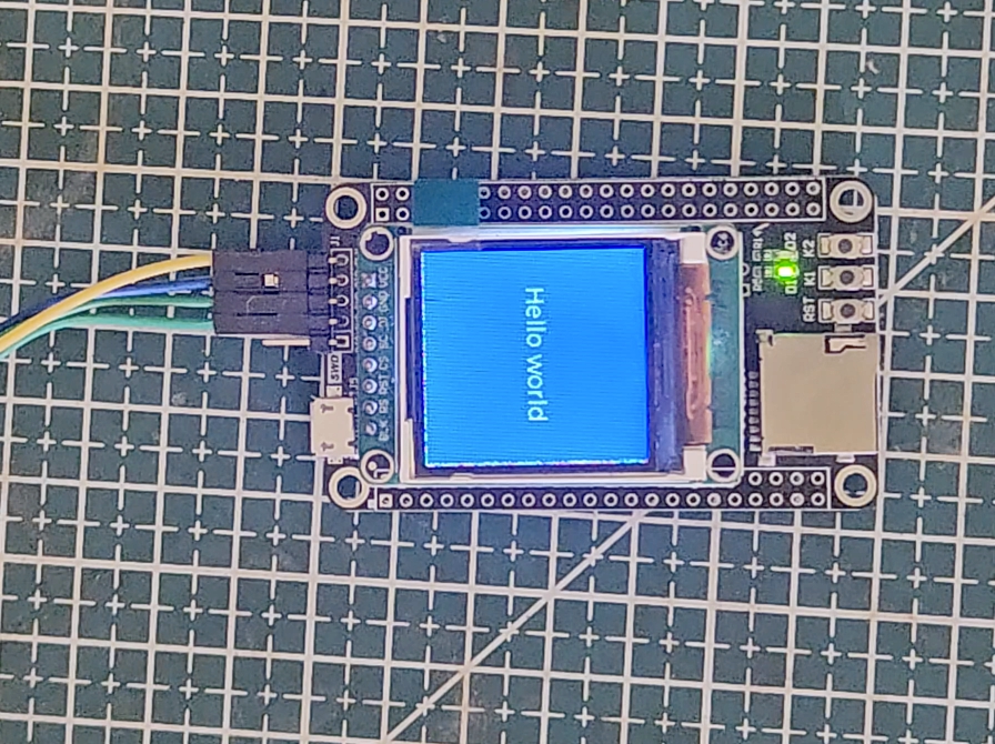
You can see the Display background colour is set to blue whereas the text “Hello world” is in white.
STM32 LVGL Tutorial Series
LVGL on STM32 || PART 2
LVGL on Riverdi STM32-H7 Display
LVGL on STM32 || PART 4
LVGL ON STM32 || PART5
LVGL on STM32 || PART 6
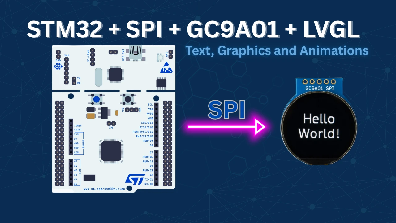
STM32 GC9A01 Round Display: SPI & LVGL Integration Guide
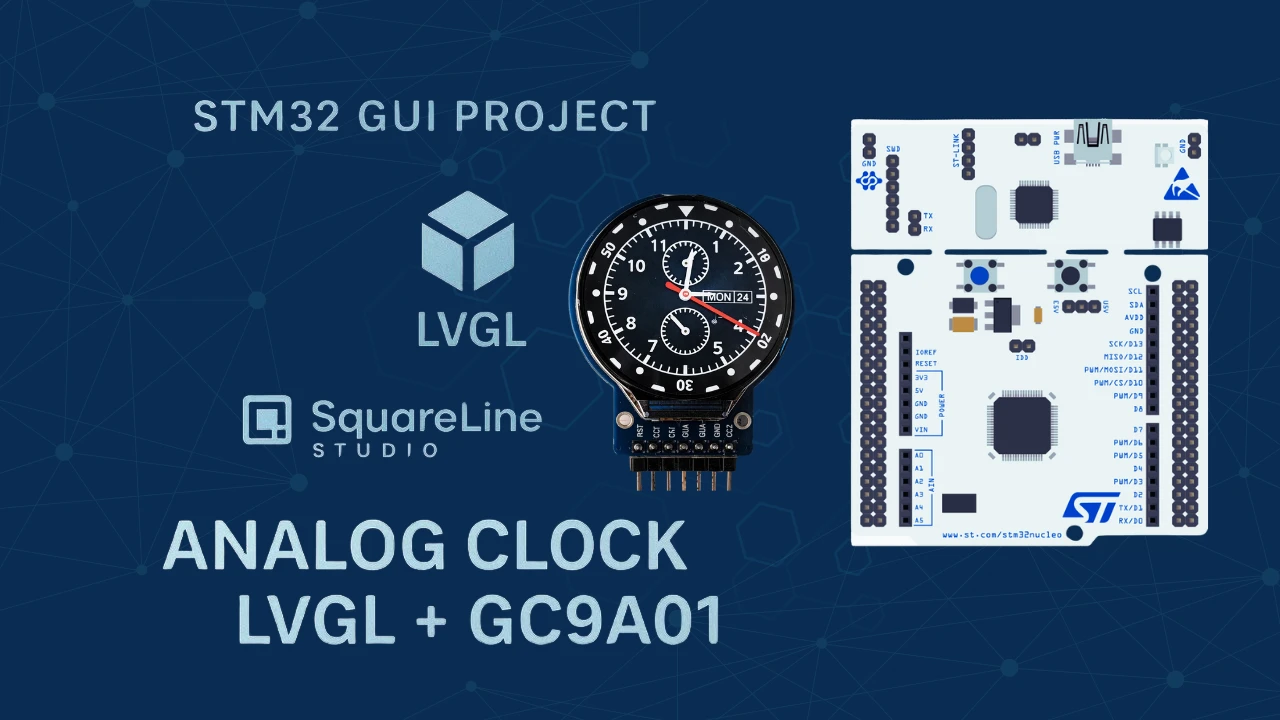
STM32 Analog Clock on GC9A01 — LVGL, SquareLine Studio & RTC

Subscribe
Login
0 Comments
Newest
