Configure UART & Transmit Data
This tutorial is the start of a new series on the UART peripheral of STM32 Microcontrollers. In this series we will cover different ways of transmitting and receiving data over the UART protocol. We will also see different UART modes available in the STM32 microcontrollers and how to use them.
In this tutorial, we will understand the connection and configuration of different parameters of UART available in the cubeMX. We will also transmit the data over UART and receive it on a serial console in the computer.
UART vs USART
UART stands for Universal Asynchronous Receiver Transmitter whereas the USART stands for Universal Synchronous Asynchronous Receiver Transmitter. The term Synchronous enables the USART to send an additional clock signal to the receiving device. The data is then sampled at a predefined edge (Rising or Falling) of the clock. The USART mode uses 3 pins (clock, Tx and Rx) compared to the 2 pins (Tx and Rx) used in the UART.
The most widely used synchronous communications are I2C, SPI, etc. The USART, in a way, can act as the SPI master to send the data to the slave. The synchronous communication is also used when communicating with a smartcard.
We will use the UART for the major part of this series as it has wider applications compared to the USART.
Connection
We will use the STM32 MCU to send the data to the computer. Some of the Nucleo and Discovery dev boards from ST supports the virtual com port. This feature enables the USB connected for the ST link to be also used for the data transmission between the MCU and the computer.
The Virtual Com Port is supported by many Nucleo and Discovery boards but not all. You need to check the schematic of the board to confirm whether the respective board supports it.
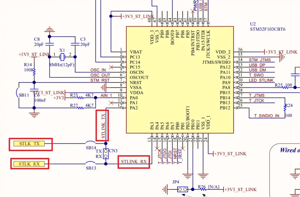
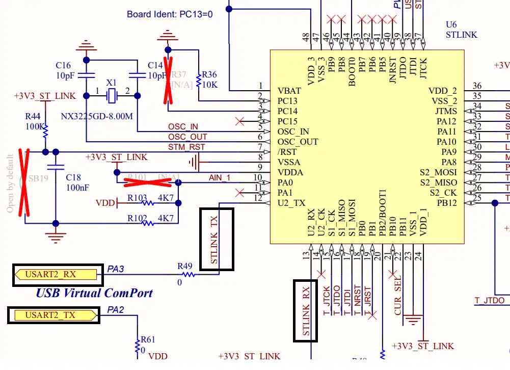
Below are the images from the schematic of the Nucleo F446RE and Discovery F412.
As you can see in the images above, both Nucleo F446RE and Discovery F412 supports the USB Virtual Com Port. So if you are using either of these boards, you do not need to use an additional module to communicate to the computer. The USB used for the ST link can also be used for the communication.
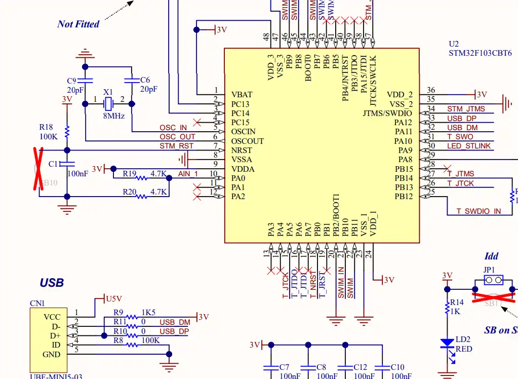
Not all the boards support this Virtual Com port feature. Below is the image from the schematic of the very famous STM32F4 Discovery board.
As you can see in the image above, there is no virtual com port in the F4 Discovery board. In such cases we can use some module to convert the UART signals to the USB, which is connected to the computer.
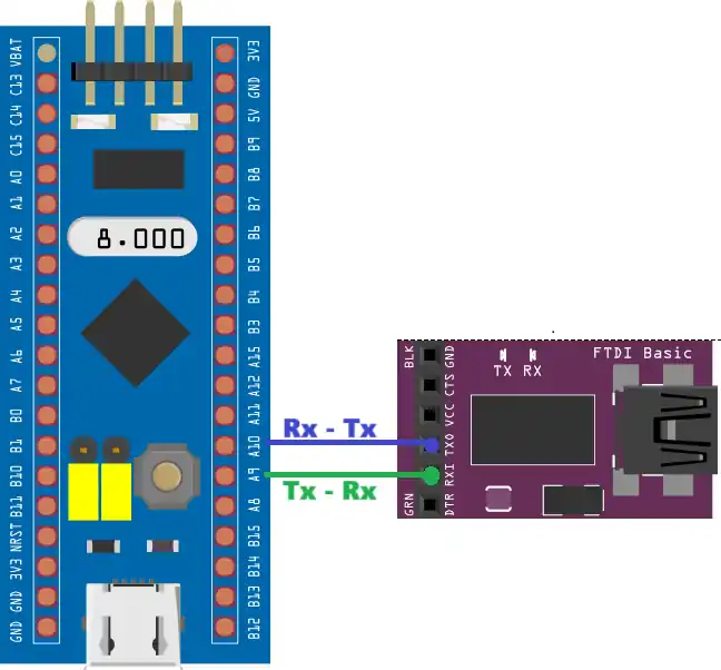
Below is the image showing the connection between the MCU and the FT232 USB to UART converter.
The UART is always connected in the cross connection, connecting the TX pin of the MCU to the RX of the device and the RX to the TX of the device. The module then connects to the computer using the USB.
Configuration
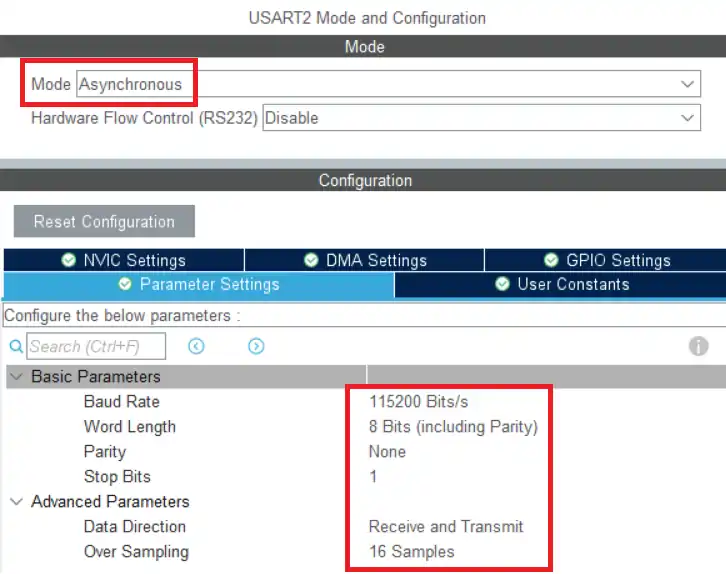
Below is the image showing the UART configuration in cubeMX.
We will use the Asynchronous Mode for the communication. Only 2 pins are used in the Asynchronous mode, TX and RX.
The baud rate is set to 115200. We need to use the same baud rate for the receiver device also.
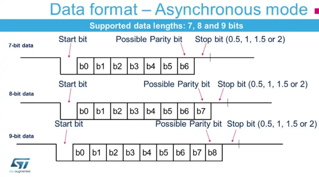
Word length consists of the data bits and the parity bit. STM32 supports different word lengths of 7 bits, 8 bits and 9 bits. A typical UART frame is shown in the image below.
The frame consists of a start bit, data bits and stop bits. we are using 8 data bits with no parity bit and 1 stop bit. We need to use the same configuration in the receiver device also. The data direction is set to Receive and Transmit.
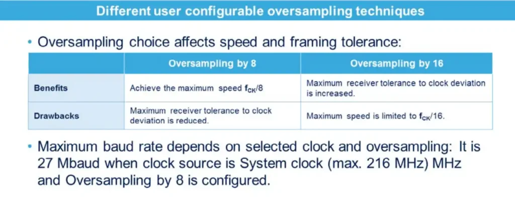
The oversampling is used to increase the tolerance of the receiver to the clock deviation. But it also reduces the maximum baud rate the device can achieve. The image below explains the oversampling and max baud rate.
This is all the configuration we need to do in the cubeMX. Let’s see the code now.
The Code
We can only send the ascii characters via the UART. Below we will see how to send a simple string and a number, by converting it to the character format.
Send string
We can directly send a string via the UART. The code below sends the string every 1 second.
uint8_t data[] = "Hello world\n";
int main()
{
 ....
 while (1)
 {
   HAL_UART_Transmit(&huart2, data, 12, 1000);
   HAL_Delay(1000);
 }
}
Here we define an array (data) which contains the string to be sent to the UART. Then call the function HAL_UART_Transmit in the while loop every 1 second.
The parameters of the function are as follows:
- @UART Instance, huart2
- @pointer to the data array, data
- @size of the data in bytes, 12
- @timout in case of error, 1000ms
Send number
As I mentioned we can not send the number directly to the UART. It only transmits the data in the ascii format. To send the number, we first need to convert each digit of the number to the character format and then send the data to the UART.
#include <stdio.h>
uint8_t number = 123;
uint8_t numarray[4];
int main()
{
 ....
 while (1)
 {
   sprintf(numarray, "%d\n", number);
   HAL_UART_Transmit(&huart1, numarray, 4, 1000);
   HAL_Delay(1000);
 }
}
Here we will send the number 123 to the UART. We first need to define an array of size at least the number of digits of the number.
The sprintf function is used to convert the number to the character format. The format specifier, %d, is used to convert the integral value (123).
After conversion the characters are stored in the array, numarray. We send this array to the UART every 1 second.
Result
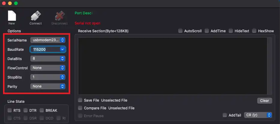
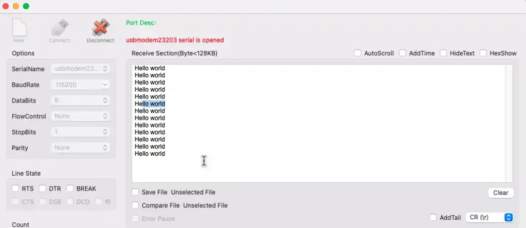
The Serial console on the computer should have the same configuration as we did for the STM32 in the cubeMX. The image below shows the configuration with the baud rate of 115200, 8 data bits with 1 stop bit and no parity.
The data sent by the STM32 is received in the serial console. The image below shows the data, “Hello world”, printed several times. It was sent every 1 second by the MCU.
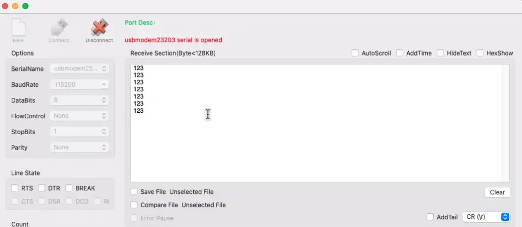
We also sent the number to the UART. The image below shows the number output on the console.
