Interface I2C-LCD1602 (AIP31068) with STM32
In the past, we have covered how to interface LCD1602 via the I2C, and in the parallel mode. In parallel mode, the LCD footprints remain small, but the pin requirement for the LCD to connect to the MCU is very high. This issue with the pin requirement is handled by using an I2C connector module, like PCF8574, which connects at the back of the LCD1602. It reduces the pins required to connect to the MCU to 4, but the entire setup becomes bulky.
Today we have one more type of LCD1602 display, which has the same footprint as the LCD1602 and it uses just 4 pins to connect to the MCU. This module has the I2C converter built onto the display itself, that is why we do not need to connect any external converter.
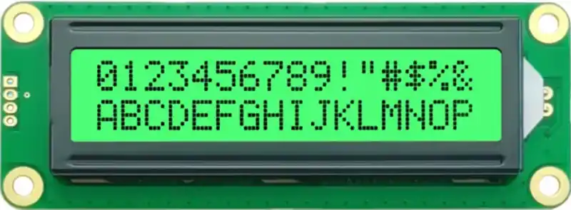
As you can see in the image above, there are only 4 pins available on the display. In today’s tutorial, we will cover how to interface this display with STM32.
VIDEO TUTORIAL
You can check the video to see the complete explanation and working of this project.
The Connection
Below the image shows the connection between the display and the Nucleo board.
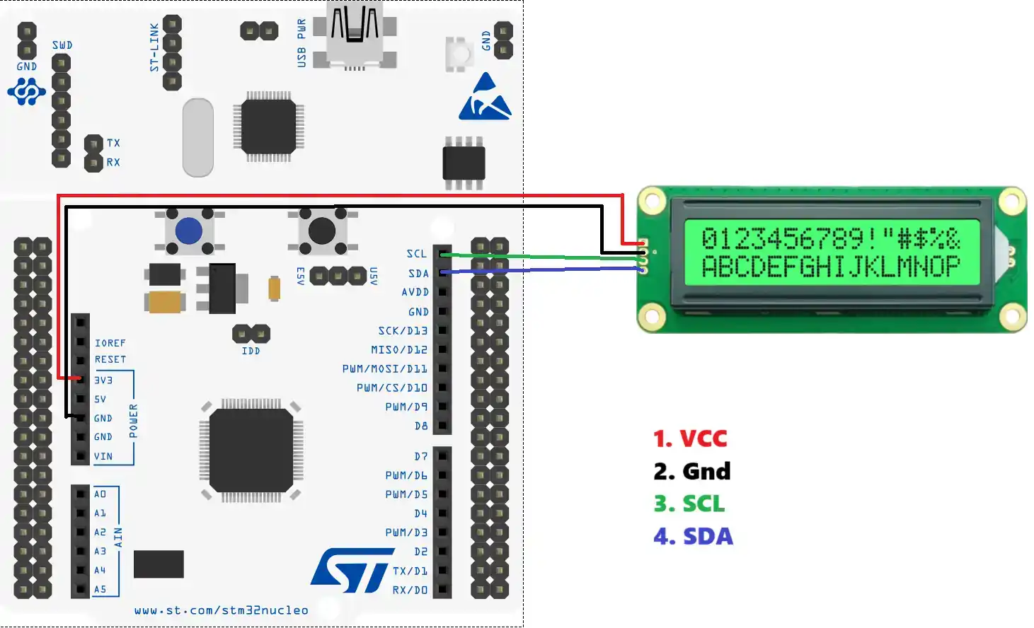
The Display can be powered with 3.3V or 5V. I am using 3.3V to power it from the nucleo board itself. The SCL pin is connected to the SCL pin on the nucleo, and the SDA pin is connected with the SDA pin on the board.
CubeMX Configuration
There is not much we need to configure in the cubeMX. Below is the image showing the I2C configuration.
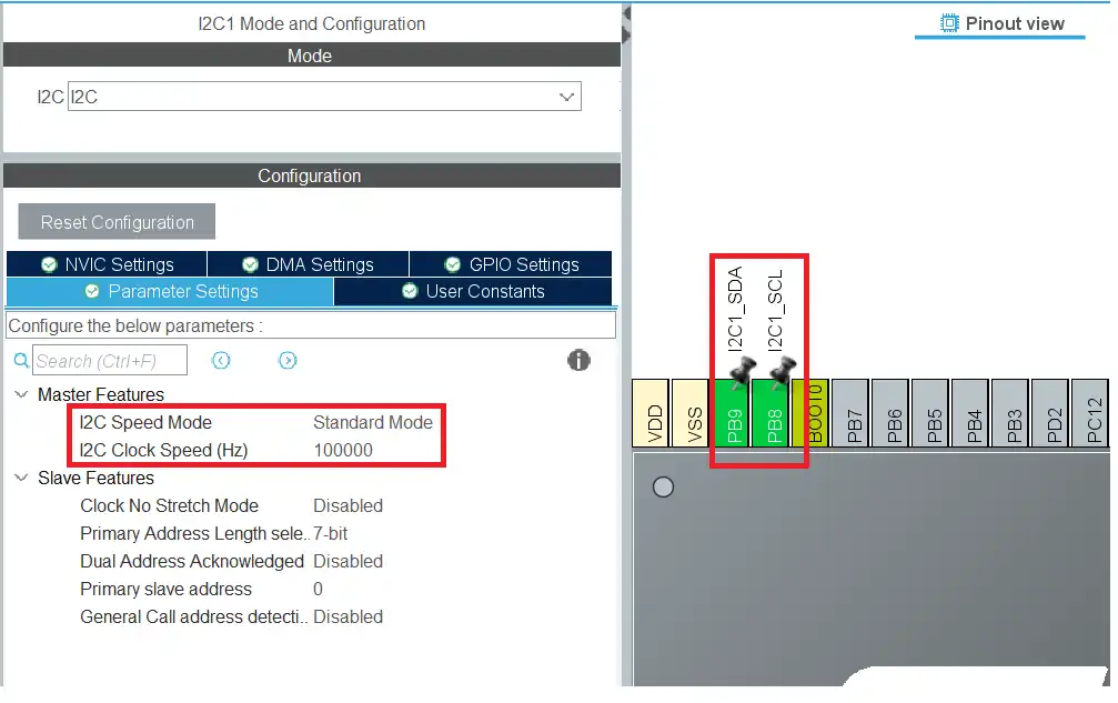
The I2C1 is configured with the clock speed of 100KHz. The pins PB8 is configured as the I2C_SCL (Clock) and the pin PB9 is configured as the I2C_SDA (Data) .
The Slave Address
The I2C-LCD1602 uses the AIP31068 driver IC. Since it has the I2C built in, it must have the slave address for the same. Below is the image from the AIP31068 driver datasheet.
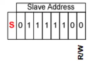
We know that the HAL library uses the 8 bit address for the slave device, so we need to consider the R/W bit as well. Considering the R/W bit as 0 for the write operations, the device address is 0x7C.
Sending Command
We send the commands to the display to initialize it as per the needed configuration. We also send the commands to change the cursor position during the runtime.
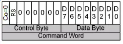
As per the datasheet, the command or data must be sent as a 16 bit word. The MSB of this word is the control byte and the LSB is the data byte.
Below is the function to send the command to the display.
void lcd_send_cmd (char cmd)
{
	uint16_t command_word = 0;
	command_word = cmd;  // rs=0
	uint8_t cmd_t[2];
	cmd_t[0] = (command_word>>8)&0xFF;
	cmd_t[1] = (command_word)&0xFF;
	HAL_I2C_Master_Transmit (&hi2c1, SLAVE_ADDRESS_LCD,(uint8_t *) cmd_t, 2, 100);
}The lcd_send_cmd function is used to send the command to the display. The parameter of the function is the 8 bit command, which needed to be send to the display.
Here we define a 16 bit command_word. This command word contains the control byte and the data byte (command). Since we are sending the command, the RS bit must be 0 and therefore we will simply copy the command data to this variable.
We now have the 16 bit command word ready to be send to the display. The I2C bus supports 8 bit data transfer, so we need to send the data in 2 bytes. The control byte needs to be sent first, therefore we will first extract the MSB from the command word ((command_word>>8)&0xFF), and then extract the data byte (command). These extracted bytes are stored in the cmd_t array.
We will then send the cmd_t array via the I2C.
Sending Data
The data is sent in the same way as we sent the command. Below is the function to send the data to the display.
void lcd_send_data (char data)
{
	uint16_t data_word = 0;
	data_word = 0x4000|data;  //rs=1
	uint8_t data_t[2];
	data_t[0] = (data_word>>8)&0xFF;
	data_t[1] = (data_word)&0xFF;
	HAL_I2C_Master_Transmit (&hi2c1, SLAVE_ADDRESS_LCD,(uint8_t *) data_t, 2, 100);
}The lcd_send_data function is used to send the data to the display. The parameter of the function is the 8 bit data, which needed to be send to the display.
Here we define a 16 bit data_word. This data word contains the control byte and the data byte. Since we are sending the data, the RS bit must be 1 and therefore we will write a 1 to the 14th position of this word, and copy the data to the LSB of this word.
We now have the 16 bit data word ready to be send to the display. The I2C bus supports 8 bit data transfer, so we need to send the data in 2 bytes. The control byte needs to be sent first, therefore we will first extract the MSB from the data word ((data_word>>8)&0xFF), and then extract the data byte. These extracted bytes are stored in the data_t array.
We will then send the data_t array via the I2C.
The function lcd_send_data can display a single character on the LCD. To display an entire string, we can use the lcd_send_string function as shown below.
void lcd_send_string (char *str)
{
	while (*str) lcd_send_data (*str++);
}The parameter of this function is the pointer to the string or array, that you want to display on the LCD.
The LCD Initialization
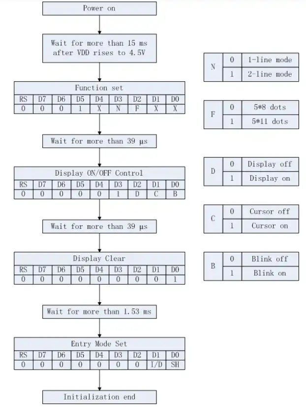
The LCD initialization sequence is given in the datasheet. The image below shows the sequence.
Below is the code for LCD initialization.
void lcd_init (void)
{
	HAL_Delay(50);  // wait for >40ms

	lcd_send_cmd (0x28); // Function set --> DL=0 (4 bit mode), N = 1 (2 line display) F = 0 (5x8 characters)
	HAL_Delay(1);
	lcd_send_cmd (0x08); //Display on/off control --> D=0,C=0, B=0  ---> display off
	HAL_Delay(1);
	lcd_send_cmd (0x01);  // clear display
	HAL_Delay(5);
	lcd_send_cmd (0x06); //Entry mode set --> I/D = 1 (increment cursor) & S = 0 (no shift)
	HAL_Delay(1);
	lcd_send_cmd (0x0C); //Display on/off control --> D = 1, C and B = 0. (Cursor and blink, last two bits)
}The above sequence is as per the instructions given in the datasheet. The code is commented properly, so that you can understand it.
The main Function
In the main function, we will initialize the LCD first. Then display the data at the desired position.
int main()
{
  ...
  ...
  lcd_init();  // Initialize he LCD
  lcd_put_cur(0, 0);  // put cursor at the beginning of TOP Row
  lcd_send_string("Hello World");  // display the string
  lcd_put_cur(1, 0);   // put cursor at the beginning of Bottom Row
  lcd_send_string("ControllersTech");  // Display the string
  while (1)
  {
   ....
  }
}We have 16×2 display, so there are 2 Rows (0 or 1) and 16 columns (0 to 15). The function lcd_put_cur can be called to put the cursor at any desired location. When the data to the LCD is sent continuously, the cursor position increments automatically.
Result
Below is the image showing the output of the above code.
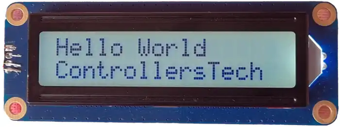
You can see the strings are displayed at their respected positions, as we programmed them.


Instead of the above data and command write which converse data to uint16_t and then to two uint8_t why not use as below
void lcd_send_data (char data)
{
uint8_t data_t[2];
data_t[0] = 0x40; // for rs=1 and 0 for rs=0
data_t[1] = data;
HAL_I2C_Master_Transmit (&hi2c1, SLAVE_ADDRESS_LCD,(uint8_t *) data_t, 2, 100);
}
because I am trying to teach something as per the datasheet.