Multiplexer 74HC4051 and STM32
Today, in this tutorial, we are going to interface 74HC4051 Multiplexer/Demultiplexer with STM32. I will cover the multiplexing part first.
what is a multiplexer
Well, basically multiplexer is a device that can take multiple inputs, and have only one output. At some random time, the output of the mux is connected to only one input. And which input it must be connected to, can be selected by using select pins.
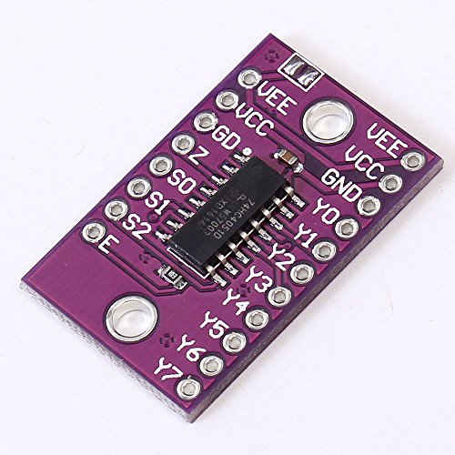
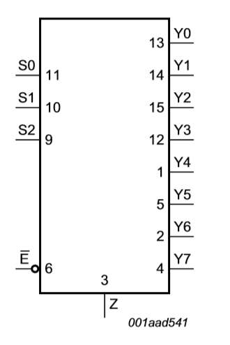
74HC4051 is a 8:1 mux, that means that it have 8 input pins (Y0 to Y7), and 1 output pin (Z). To control these 8 input pins, it have 3 select pins (S0 to S2). You can see that in the picture below.
How does it work
The working of a mux is pretty simple, and it remains same for other multiplexers too.
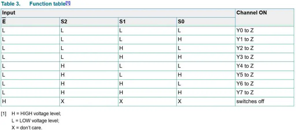
Enable pin (E) is an active low pin. It means that the device will be enabled whenever the pin is low. Now, as shown above, the combination of select pins must be pulled low to connect the respective input pin (Y) to the output (Z).
To show the working, I am going to connect 3 ADC sensors to the input pins (Y0 to Y2), and I will read the sensor values from the output pin (Z). Below is the setup of my cube MX.
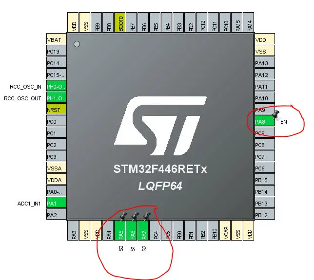
As you can see 3 select pins are connected to PA4, PA5, and PA6 and enable pin is connected to PA7. I have also renamed them accordingly.
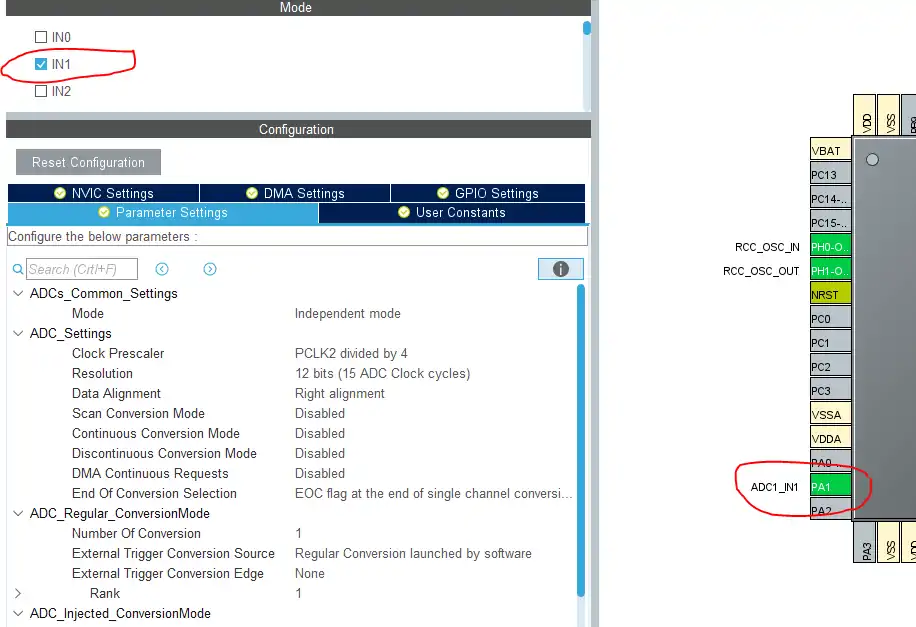
Now, as i am reading the ADC sensor value, the Z pin is connected to the ADC CHANNEL 1 i.e. PA1.
This is it for the setup, now let’s take a look at the coding part.
Some insight into the code
NOTE:- The reference of some of the functions is taken from sparkfun.com and the link to the code is https://learn.sparkfun.com/tutorials/multiplexer-breakout-hookup-guide/all
const int selectPins[3] = {S0_Pin, S1_Pin, S2_Pin};I have defined selectPins as an array of the select pins for simplicity.
void selectMuxPin(int pin)
{
  for (int i=0; i<3; i++)
  {
    if (pin & (1<<i))
      HAL_GPIO_WritePin(selectpinsPort, selectPins[i], GPIO_PIN_SET);
    else
      HAL_GPIO_WritePin(selectpinsPort, selectPins[i], GPIO_PIN_RESET);
  }
}
The function, selectMuxPin is used to select the respective pin of the mux as input pin. Basically it connects the respective Y pin to the Z pin. For eg- selectMuxPin(2) will connect Y2 to Z pin and we can read the value of the sensor connected to the Y2 pin.
The argument of the selectMuxPin i.e. pin, can take the values from 0 to 7.
HAL_GPIO_WritePin(GPIOA, EN_Pin, GPIO_PIN_RESET);   // pull the EN pin low

  // set all the select pins
  for (int i=0; i<3; i++)
  {
	  HAL_GPIO_WritePin(selectpinsPort, selectPins[i], GPIO_PIN_SET);
  }
First of all,we have to pull the enable pin (E) LOW, so as to enable the mux.
Also set all the select pins as HIGH, so that we can select the respective mux pin by pulling them (select pins) low.
for (int i=0; i<3; i++)
	  {
		  selectMuxPin(i);  // select one mux pin at a time

		  HAL_ADC_Start(&hadc1); // start the ADC

		  HAL_ADC_PollForConversion(&hadc1, 100);  // poll for conversion

		  value[i] = HAL_ADC_GetValue(&hadc1);  // store adc value in value

		  HAL_ADC_Stop(&hadc1);
	  }
We are going to read the data using pollforconversion, as it’s the easiest way to read ADC value. So basically the steps are as follows
- Select the respective pin of the mux that you want to read
- Start the ADC
- Poll for conversion to finish
- Read the value of the sensor
- Stop the ADC
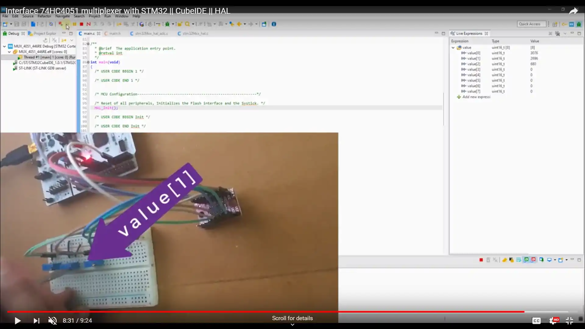
Result
Using 74HC4051 as DeMultiplexer
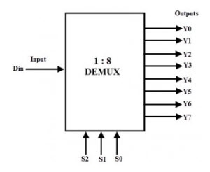
Opposite to mux, a demultiplexer is a device that takes only one input, and that can be connected to different outputs, again based on the select pins. 74HC4051 can be used as 1:8 Demux. The block diagram is shown below
I am using the same functions as above to selectPins or to selectMuxPin. The only changes here will be regarding the Z pin. This time Z pin is selected as output in the CubeMX.
for (int i=0; i<8; i++)
{
  selectMuxPin(i);
  HAL_GPIO_WritePin(Z_GPIO_Port, Z_Pin, GPIO_PIN_RESET);
  HAL_Delay(250);
}
So, all the Y pins are connected to the LEDs. And when the Z pin is pulled low, the respective Y pin is also pulled low, and the LED connected will turn ON. In the above code, the output pin of the DEMUX changes every 250 ms, and Z pin is again pulled low.