
Home ▸ STM32 Tutorials ▸
Updated On: January 10, 2026
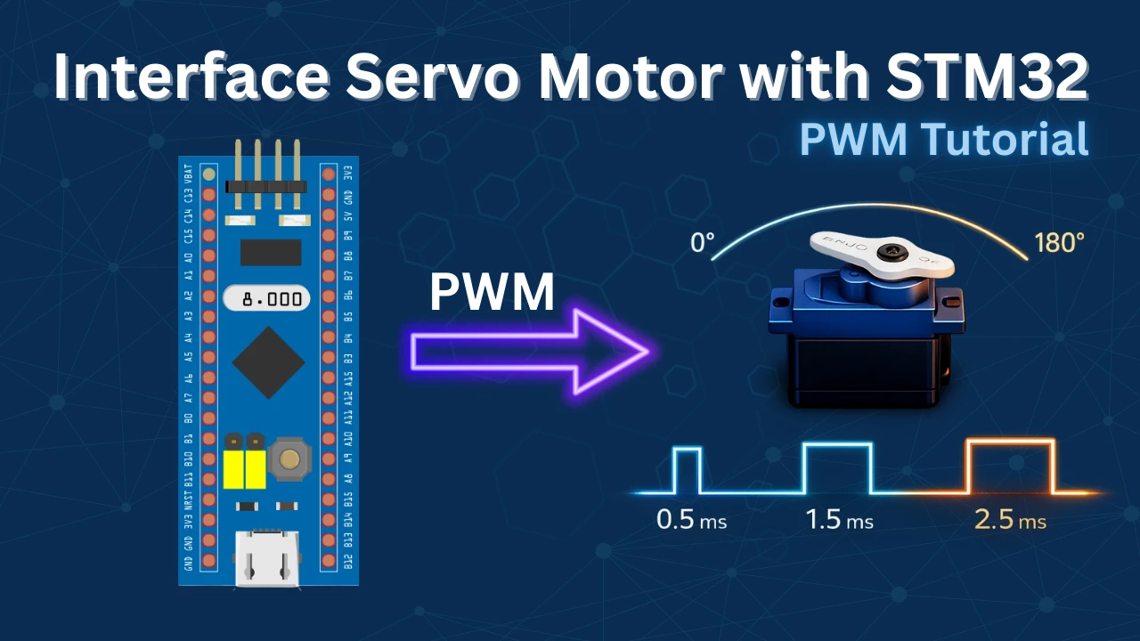
Controlling a Servo Motor with STM32 Using PWM (Step-by-Step Guide)
Servo motors are widely used in embedded and robotics applications where precise angular positioning is required. Unlike regular DC motors, a servo motor allows accurate control over its shaft position by interpreting a PWM (Pulse Width Modulation) signal. This makes servos ideal for applications such as robotic arms, camera gimbals, automation systems, and control mechanisms.
In this tutorial, we will learn how to control a standard RC servo motor using an STM32 microcontroller. The servo is driven using a hardware timer configured in PWM mode through STM32CubeMX, while the control logic is implemented using the HAL library. By adjusting the PWM pulse width, we can rotate the servo shaft to specific angles, making this tutorial a solid foundation for motion-control based STM32 projects.
Related Tutorials:
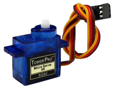
Introducing Servo Motor
A servo motor is a type of rotary actuator designed to provide accurate control over angular position. It operates using a closed-loop feedback system that constantly monitors the shaft position and corrects it according to the incoming PWM (Pulse Width Modulation) signal. This feedback mechanism allows the servo to maintain precise positioning even when external forces are applied.
Due to their accuracy, reliability, and ease of control, servo motors are extensively used in embedded systems and robotics for driving mechanical components such as joints, levers, sensors, and steering mechanisms where controlled movement is essential.
Key Features of a Servo Motor
- Precise Position Control – The shaft can be rotated to a defined angle, commonly ranging from 0° to 180°, with good repeatability.
- Built-in Feedback System – An internal potentiometer or encoder continuously tracks the shaft position and ensures accurate movement.
- Fast Response with High Torque – Delivers quick movement and sufficient torque, making it suitable for motion-control applications.
- Simple Three-Wire Interface – Requires only Power, Ground, and a PWM control signal, making it easy to interface with microcontrollers.
Applications of Servo Motors
- Robotic arms and grippers
- Pan-tilt camera systems and gimbals
- Steering control in RC vehicles
- Automation and control systems
- Sensor positioning and scanning mechanisms
- Educational and DIY robotics projects
How do the Servo Motor works
Regular servos can go from 0° to 180° depending on the width of the pulse signal. Basically you need to keep the pulse (+5v) high for a particular amount of time. Some of the important timings are mentioned below.
- 0.5 milliseconds pulse width corresponds to 0°.
- 1.5 milliseconds pulse width corresponds to 90°.
- 2.5 milliseconds pulse width corresponds to 180°.
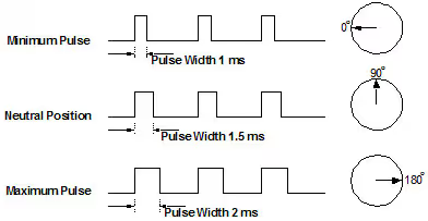
The period of the PWM signal must be 20ms or we can say the frequency of the signal must be 50 Hz.
As the Pulse increases from 0.5ms to 1.5ms, the Angular displacement increases from 0 to 90°. The motor reaches 90° when the pulse width is 1.5ms. When the pulse width further increases from 1.5ms to 2.5ms, the Angular displacement further increases from 90° to 180°.
STM32CubeMX Configuration
In this section, we’ll configure the STM32 microcontroller using STM32CubeMX. This includes setting up the PWM output using a timer, selecting the appropriate GPIO pin for the servo signal, and adjusting the prescaler and auto-reload values to generate a 50Hz PWM signal. These settings are essential to ensure smooth and accurate control of the servo motor.
Clock Configuration
The clock configuration for this project is shown below.
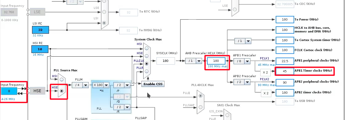
- External Crystal (8MHz) is used to provide the clock via the PLL.
- The system is running at 180MHz.
- I am going to use the TIM2 for the PWM, which is connected to the APB1 Bus (Check this Image).
- The APB1 Timer clock is at 45MHz right now.
Timer Configuration
The TIM2 configuration is shown below.
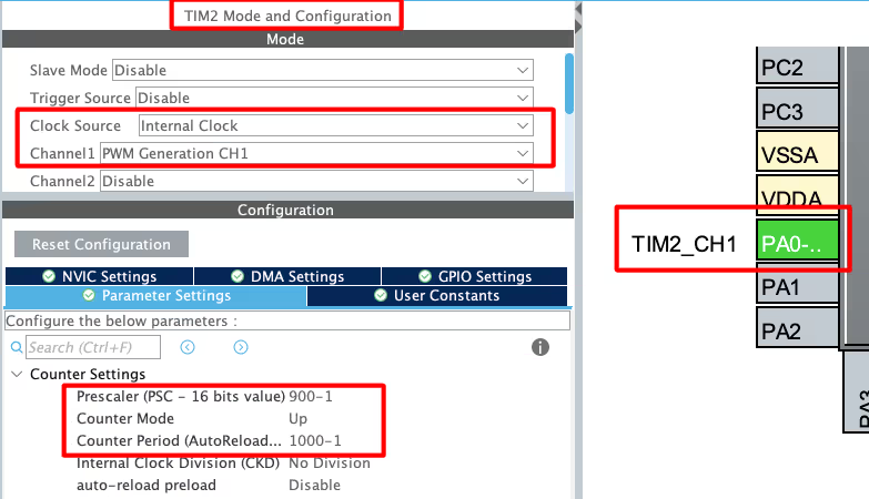
- Select the PWM channel for the Timer, I am using Channel 1.
- Set the Clock source as internal clock, which is at 45 MHz (same as APB1).
- Pin PA0 is set as the PWM output Pin and we will connect it to the Servo Motor Signal pin.
The output Frequency of the PWM signal depends on 3 parameters, Timer Clock, ARR and Prescaler
Out of these parameters, the Timer Clock will remain constant at 45MHz throughout the project. We want to generate the PWM signal with the Frequency of 50Hz. To do so, I am setting the Prescaler and ARR values as shown below.
Here the Prescaler value is not as important but the ARR plays a very important role. We will see this in details below.
Note that the Pres and ARR input values must be 1 less than the actual values. This is because the library add a 1 to this value at the register level, so we must keep it 1 less than the value we want to pass.
Setting the PWM Pulse Width for Servo Control
The servo motor responds for the pulse width of 0.5ms to 2.5ms. Also the pulse period is 20ms, so in terms of Duty%, the pulse width for the extreme ends can be calculated as shown below.

Now keeping the above duty cycles in mind, our choice of ARR affects the variations available for the pulse width.
For eg- Let’s assume we choose the ARR of 100.
- To generate a duty cycle of 2.5%, we need to set the value 2.5 to the Compare Register (CCR).
- Similarly to generate a duty cycle of 12.5%, we need to set the value 12.5 to the Compare Register (CCR).
This will give us only 10 steps (12.5 – 2.5) of variations between the extreme positions. Each step will result in a large variation in the Angular Displacement of the motor.
Here in the project I chose the ARR value of 1000. The Compare Register value depends on the ARR, so the values for the Duty cycles are as follows:

This set up will result in 100 steps (125 – 25) of variations between the extreme ends. We will have more variations for the Angular Displacement.
Wiring Diagram
Below is the image showing the connection between the STM32 and the servo motor.
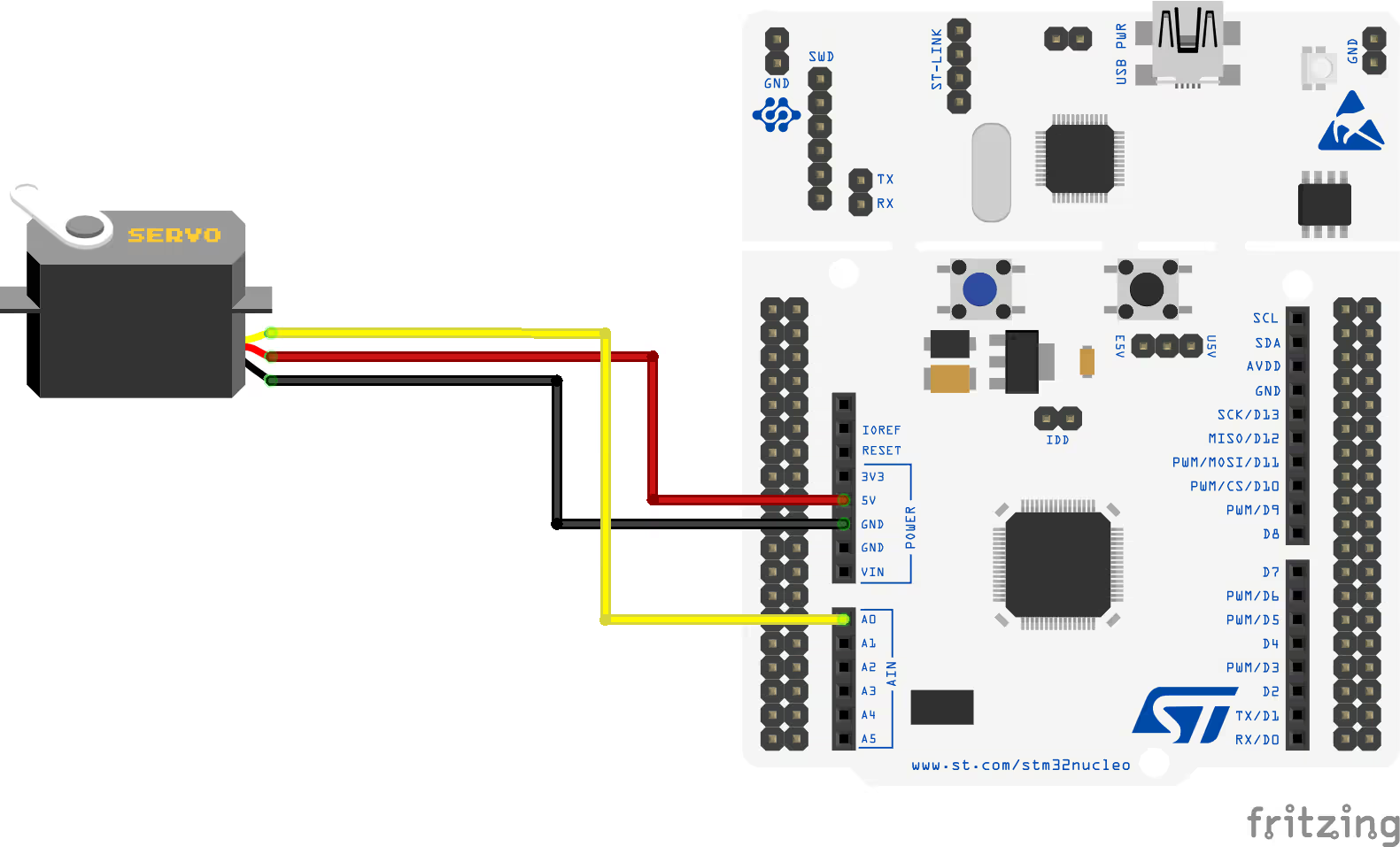
I am powering the motor from the STM32 board itself.
- Black/Brown ground wire from the motor connects with the Ground of the board.
- Red power wire from motor connects to the 5V of the board.
- Yellow or White PWM wire from motor connects to the pin PA0 of the STM32. This is TIM2 CH1, which we have configured as the PWM out pin.
STM32 Code for Servo Motor Control
Initialize the timer in PWM mode to begin generating the signal. In this example, Timer 2 Channel 1 is used to output the PWM required to control the servo motor.
HAL_TIM_PWM_Start(&htim2, TIM_CHANNEL_1);while (1)
{
htim2.Instance->CCR1 = 25; // duty cycle is .5 ms
HAL_Delay(2000);
htim2.Instance->CCR1 = 75; // duty cycle is 1.5 ms
HAL_Delay(2000);
htim2.Instance->CCR1 = 125; // duty cycle is 2.5 ms
HAL_Delay(2000);
}Inside the while loop, we will update the timer’s compare register to control the servo angle:
- First, set the compare value to 25, which moves the servo to 0°.
- After a 2-second delay, update the compare value to 75, rotating the servo to 90°.
- Wait another 2 seconds, then set the value to 125, positioning the servo at 180°.
This loop continues indefinitely, causing the servo to rotate between 0°, 90°, and 180°, with a 2-second pause at each position before moving to the next.
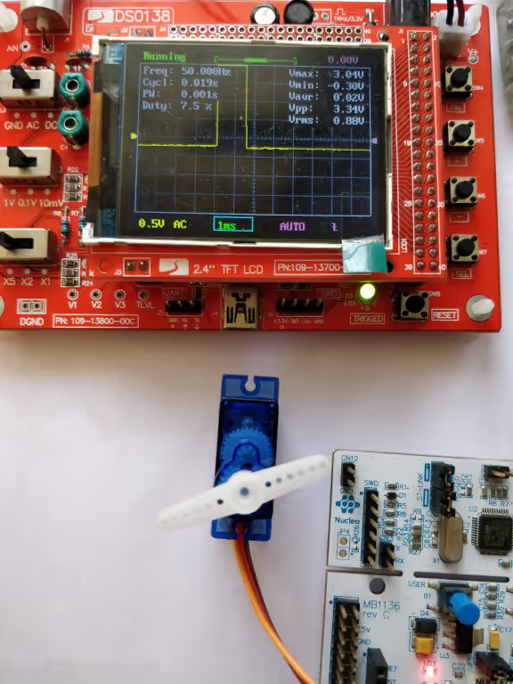
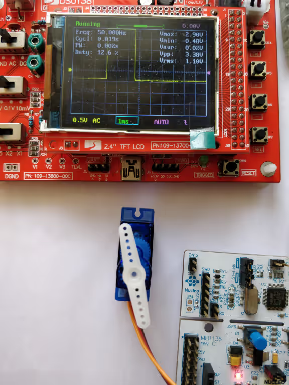
Result showing the working of Servo Motor
This section shows the servo motor rotating to 0°, 90°, and 180° based on the PWM signal from STM32. The smooth movement and timed delays confirm that the PWM configuration is working correctly.
0° Rotation
Below is the image showing the servo positioned at 0° when the CCR value is set to 25, basically a Duty Cycle of 0.5ms.
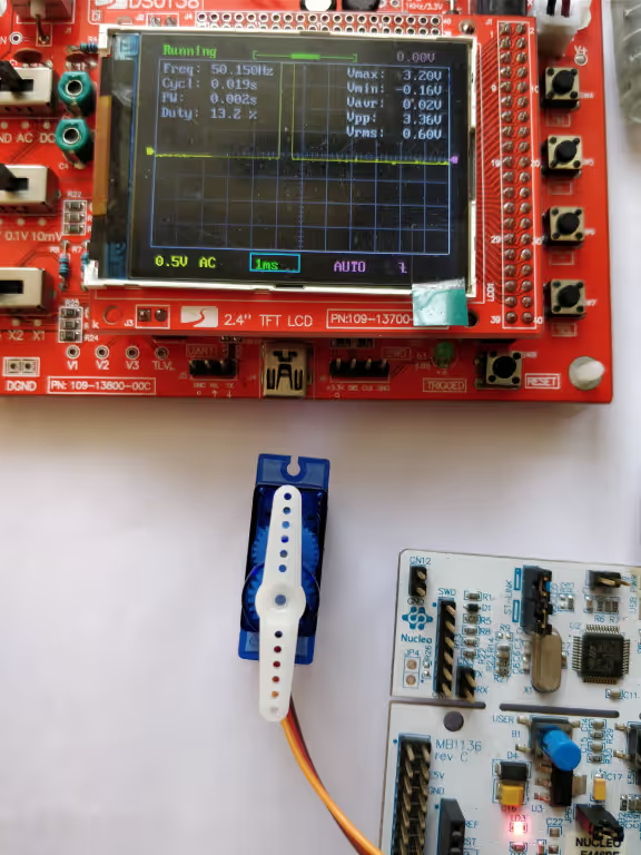
90° Rotation
Below is the image showing the servo positioned at 90° when the CCR value is set to 75, basically a Duty Cycle of 1.5ms.
180° Rotation
Below is the image showing the servo positioned at 180° when the CCR value is set to 125, basically a Duty Cycle of 2.5ms.
Controlling the Angle of Rotation using PWM
As I have already mentioned, the regular servo works between a pulse of width 0.5ms to 2.5ms. This means the servo covers the angle of 180° in 2ms Pulse difference.
We can use this to calculate the pulse width required for each 1° increment in the angle. I have tried to explain it in the picture below
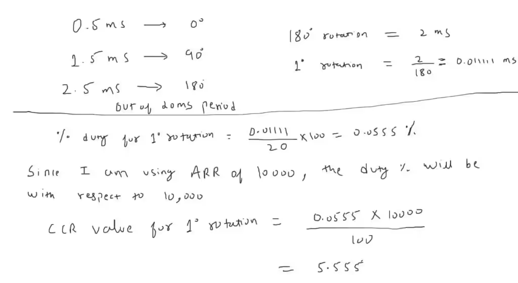
So we have the CCR (Capture Compare Register) value of 5.55 for 1° rotation of the servo motor. Please Note that this calculation is done with the ARR value of 10000.
We first need to configure the timer with the new ARR and Prescaler values. Below is the image showing the cubeMX configuration.
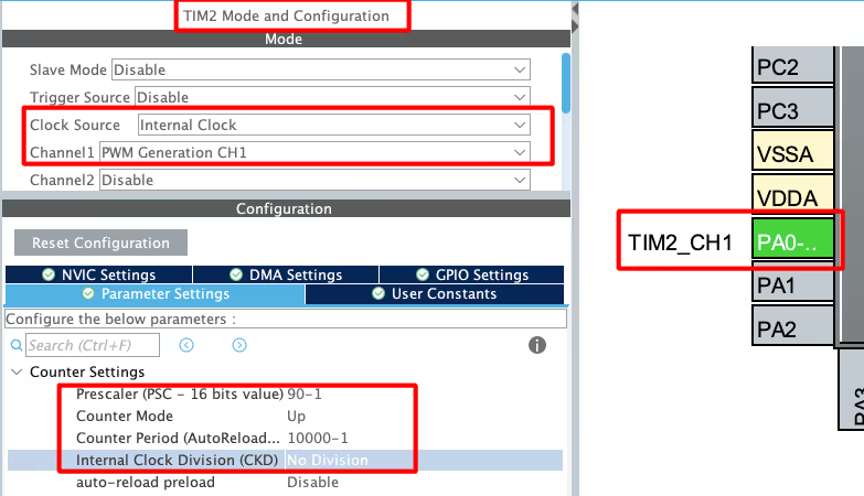
Since we have increased the ARR from 1000 to 10000, we need to reduce the prescaler from 900 to 90. This is to make sure that the output frequency of the PWM signal remains 50Hz.
The pulse values also change as per the ARR. Below are the pulse values for the extreme ends.

For the pulse value of 250, the motor will be at 0° and for the value of 1250, the motor will be at 180°. We can rotate the motor to any angle between between these values, but remember that the pulse value needs to be higher than 250.
#define per_deg 5.55  //pulse value for 1° Rotation
int main()
{
  ....
  HAL_TIM_PWM_Start(&htim2, TIM_CHANNEL_1);
  int angle = 5;  //5°
  int pulse = 250 + (5*per_deg);  // calculate pulse value, starting from 250
  __HAL_TIM_SET_COMPARE(&htim1, TIM_CHANNEL_1, pulse);  // TIM2->CCR1 = pulse
  while (1)
  {}
}Here we will simply calculate the pulse value for the respective angle. And then pass the value to the Compare Register of the timer. The pulse value of 250 represents the 0° rotation, hence the pulse for any angle will be calculated above this value.
VIDEO TUTORIAL
STM32 Servo Motor Control Using PWM – Video Tutorial
This tutorial demonstrates how to control a standard servo motor using an STM32 microcontroller with PWM. You will learn how to configure an STM32 timer in PWM mode using STM32CubeMX and control the servo position by adjusting the compare register values through HAL functions. The video walkthrough explains the PWM timing requirements, pulse width to angle mapping, and practical implementation to rotate the servo to 0°, 90°, and 180°, helping you understand real-world motion control using STM32.
Watch the VideoConclusion
In this tutorial, we explored how to control a standard servo motor using an STM32 microcontroller through PWM signal generation. We covered the working principle of a servo motor, understood how pulse width determines angular position, and configured an STM32 timer in PWM mode using STM32CubeMX. By modifying the compare register values, we successfully positioned the servo at 0°, 90°, and 180°, demonstrating precise and repeatable control using the HAL library.
This approach is highly useful in embedded and robotics applications where accurate motion control is required. The concepts covered here form a strong foundation for implementing servo-based mechanisms such as robotic arms, pan-tilt systems, and automation projects. With this understanding, you can easily extend the technique to control multiple servos, implement smooth motion, or integrate servo control into more complex STM32-based systems.
Checkout More STM32 Tutorials

W25Q Flash Series Part 2 – Read Data from Device

STM32 Microsecond Delay Using HAL Timer (delay_us Example)

WS2812 LEDs using SPI

STM32 as I2C SLAVE || PART 4

BLDC Motor Control with STM32 using PWM and ESC

W25Q Flash Series Part 11 – Xecute In Place (XIP)
Send and Receive data from the WebServer using STM32
STM32 Servo Project Download
STM32 Servo Motor FAQs


(45 MHz/50 Hz) = 900 KHz. no… its 900k. No Hz.
Hello,
I want to control 2 servo motors. How can I do that? I opened 2 timer but it isnt work.
I opened 1 timer and 2 chanlles but isnt work still
why it doesnt happen when i make timer clock 90 MHz and double prescaler to 1800 -1 and keep arr 1000 -1
Great post, I think people should learn a lot from this weblog it’s rattling user genial. So much great information on here.
Hi Great WORK!
Hi
what a rich site!
tnx a lot
sorry I have a question:
1)is there any usefull sources to learn Stm32 with cube and Hal library with its detail?
I know them to some extent but I want to learn completely
tnx a lot.
I am not aware of any source. Just watch some videos, try yourself the basic stuff. And later build on those basic principals.
Also there are some samples provided by ST, you can find them in the repository folder in your pc, where the cubemx is installed