Interface TFT display with STM32
Today, in this tutorial, we will see how to interface a TFT display with STM32. This tutorial will only cover the parallel connection today.
I am using STM32CUBEIDE and STM32F103C8 microcontroller for this purpose.
Before I start, I want to mention that I did not write this code. This is a PORT from the mcufriend’s arduino code, which can be found HERE. I merely made some changes, so that it can be used with the CubeMx with a little modifications.
VIDEO TUTORIAL
You can check the video to see the complete explanation and working of this project.
SETUP
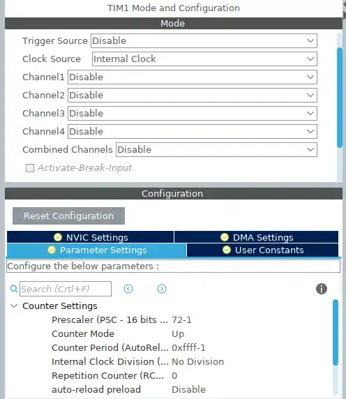
I will start by creating a project in the CubeMx (or in the CUBEIDE). Here, we need to setup the TIMER to create a delay in microseconds. Below is my setup for the same.
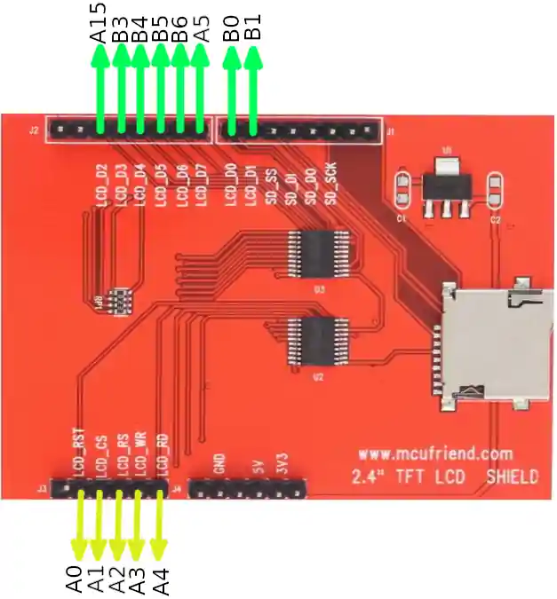
Now comes the part for setting up the Pins for the display. As, we are using the parallel connection, there are 8 DATA Pins and 5 CONTROL Pins. It would be really easy, if you connect all the data pins to the same PORT and in the same order.
For eg -> LCD_D0 -> PB0, LCD_D1 -> PB1……………… LCD_D7->PB7.
But just to show you guys, how to program in random selection of pins, I am choosing some of the Pins in random.The pins selected are as follows:
Once the code is generated, we need to copy the following files into our project:
user_setting.h
fonts.h
functions.h
tft.h
fonts.c
tft.c
These files are in the code.zip, you can download at the end of the post.
Next, just open the user_setting.h file. This is where we need to modify the code according to our setup. According to my setup the defines are as follows
#define RD_PORT GPIOA
#define RD_PIN  GPIO_PIN_4
#define WR_PORT GPIOA
#define WR_PIN  GPIO_PIN_3
#define CD_PORT GPIOA          // RS PORT
#define CD_PIN  GPIO_PIN_2     // RS PIN
#define CS_PORT GPIOA
#define CS_PIN  GPIO_PIN_1
#define RESET_PORT GPIOA
#define RESET_PIN  GPIO_PIN_0

#define D0_PORT GPIOB
#define D0_PIN GPIO_PIN_0
#define D1_PORT GPIOB
#define D1_PIN GPIO_PIN_1
#define D2_PORT GPIOA
#define D2_PIN GPIO_PIN_15
#define D3_PORT GPIOB
#define D3_PIN GPIO_PIN_3
#define D4_PORT GPIOB
#define D4_PIN GPIO_PIN_4
#define D5_PORT GPIOB
#define D5_PIN GPIO_PIN_5
#define D6_PORT GPIOB
#define D6_PIN GPIO_PIN_6
#define D7_PORT GPIOA
#define D7_PIN GPIO_PIN_5You can change them, however you have defined the pins for the LCD connection.
After defining the respective pins, we need to modify the TIMER function to create the delay in microseconds. The default setup is shown below. You can change the Timer handler, if you are not using TIMER1.
extern TIM_HandleTypeDef htim1;
void delay (uint32_t time)
{
	/* change your code here for the delay in microseconds */
	__HAL_TIM_SET_COUNTER(&htim1, 0);
	while ((__HAL_TIM_GET_COUNTER(&htim1))<time);
}
Now comes the most important part of the setup. That is, customising the “write_8” and “read_8” functions. Here you need to pay attention to whatever I am going to explain.
The write_8 function is defined below
  #define write_8(d) { \
   GPIOA->BSRR = 0b1000000000100000 << 16; \
   GPIOB->BSRR = 0b0000000001111011 << 16; \
   GPIOA->BSRR = (((d) & (1<<2)) << 13) \
               | (((d) & (1<<7)) >> 2); \
   GPIOB->BSRR = (((d) & (1<<0)) << 0) \
               | (((d) & (1<<1)) << 0) \
			   | (((d) & (1<<3)) << 0) \
			   | (((d) & (1<<4)) << 0) \
			   | (((d) & (1<<5)) << 0) \
			   | (((d) & (1<<6)) << 0); \
}- This consists of 2 parts. First, we have to clear all the Pins, that are connected to the TFT as DATA Pins.
- To clear the Pins, we have to write a HIGH (1) to the higher bits of the respective BSSR register.
- As, in my setup, the pins PA5 and PA15 are connected to the LCD D7, and LCD D2. So in GPIOA->BSRR register, only the 5th and the 15th bits are HIGH.
- The PB0, PB1, PB3 – PB6 are also connected to the data pins. And that’s why, in the GPIOB->BSRR register, the bits 0,1,3,4,5,6 are set to HIGH.
- After Setting the Respective bits, we will shift them by 16 places, so that they get cleared.
- After the pins are cleared, we have to write the data to the LCD. And to set a pin, we must set the lower bits of BSSR register as HIGH.
- According to the Setup, the LCD_D2 is connected to the PA15. So if I want to write the DATA to the LCD_D2 pin, first I will select the 2nd bit of the data (d & (1<<2)), and than shift this by 13 using <<13. This will be like adding 2 with 13 to make a total of 15, and that’s where the LCD_D2 is connected to.
- Similarly, LCD_D7 is connected to PA5. So to write the data, first we will select the 7th bit of the data (d & (1<<7)), and this time shift it RIGHT by 2 (>>2). This is like subtracting 7-2=5. And that’s where, the D7 is connected to.
- The rest of the LCD Pins are connected to the respective Pins of GPIOB, and that’s why we don’t need to shift anything there.
The next part is reading the Pins for the data from the LCD. And we do that by reading the IDR (Input Data Register) of the Respective PORT.
The read_8 is defined below
  #define read_8() (          (((GPIOB->IDR & (1<<0)) >> 0) \
                           | ((GPIOB->IDR & (1<<1)) >> 0) \
                           | ((GPIOA->IDR & (1<<15)) >> 13) \
                           | ((GPIOB->IDR & (1<<3)) >> 0) \
                           | ((GPIOB->IDR & (1<<4)) >> 0) \
                           | ((GPIOB->IDR & (1<<5)) >> 0) \
                           | ((GPIOB->IDR & (1<<6)) >> 0) \
| ((GPIOA->IDR & (1<<5)) << 2)))The process here remains the same. Except, we have to first select the GPIO Pin, and than shift it according to the position of the LCD Pin, that it is connected to. In the function above, we are first selecting the PB0 pin, and as it is connected to LCD_D0, we don’t need to shift it anywhere. Same for the PB1 also.
Next, we are selecting PA15, and as this one is connected to the LCD_D2, we need to shift it by 13 to the right ( >>13). This process continues for all other pins too.
After all the Pins work is done, we still need to select the delays according to our clock frequency. As I am using STM32F103C8 at 72 MHz, I am going to uncomment the respective code as shown below.
/************************** For 72 MHZ ****************************/
#define WRITE_DELAY { }
#define READ_DELAY { RD_ACTIVE; }You still need to uncomment the support for the TFT type that you are using. I am using HX8347#define SUPPORT_8347D
Some Insight into the CODE
ID = readID();

HAL_Delay(100);

tft_init (ID);- readID( ) reads the ID of the display, and store it in the variable ID.
- tft_init (ID) initialises the display with the ID that we read.
fillScreen(BLACK);fills the entire screen with BLACK colour. It’s more like clearing the display, if you like the BLACK background.
testFillScreen();
testLines(CYAN);
testFastLines(RED, BLUE);
testFilledCircles(10, MAGENTA);
testCircles(10, WHITE);Above are some tests, that LCD is going to perform.
printnewtstr(100, RED, &mono12x7bold, 1, "HELLO WORLD");

scrollup(100);printnewstr prints the string in the given ROW. We can customise the text colour, fonts, size of the string.scrollup is going to scroll the contents of the display in vertically upward direction.
RESULT
Here is the Picture from the video


functions.c file is not there in the downloaded project zip folder.
Nothing happens when I click the download button, I see a tiny window entitled ADVERTISEMENT which constantly shows short video clips of about 2 minutes duration then nothing happens???
please view the ad completely. The project will automatically download after the ad is finished. you can also close the ad once it is finished, the project will download afterwords.
Hi,
I am using STM32G484VET6 controller and 3.2″TFT display having LCD driverILI9341 interface 16bit parallel.Please suggest us how to do. And no zip file found for library.
I use ili9341. it dose not show anything. only a blank white screen.
Did you ever figure it out?
i’ve tried it. It took me 1 week to make this thing work. Cause I use black pill, I got some problem on the clock settings. But at the end it’s just matter of time
please, can you help me on this .. does it work for you with blackpill ?
Could someone explain the mechanism of changing resolution writing into devise memory via pointers:
p16 = (int16_t *) & _height;
*p16 = 400;
Hi
I want interface TFT LCD 3.2 inch (ssd1289) with stm32f103 and using 16bit parallel connection can you please help me .
I used this project codes and made some changes and it didn,t work
if this code doesn’t work, i can’t help. Parallel displays are too complicated to be dealt with. Better use some SPI Display, or use some controller which supports display protocols like LTDC..
Hello, thumbs up for such a great article.
All works fine, just my STM32F767 triggers a HardFault when
printnewtstr(100, RED, &mono12x7bold, 1, “Hello All”) -> calling write
size_t write(uint8_t c)
{
{
if(c == ‘\n’) {
cursor_x = 0;
cursor_y += (int16_t)textsize *
(uint8_t)pgm_read_byte(&gfxFont->yAdvance);
} else if(c != ‘\r’) {
uint8_t first = pgm_read_byte(&gfxFont->first);
if((c >= first) && (c <= (uint8_t)pgm_read_byte(&gfxFont->last)))
{
GFXglyph *glyph = &(((GFXglyph *)pgm_read_pointer(&gfxFont->glyph))[c – first]);
uint8_t w = pgm_read_byte(&glyph->width),
h = pgm_read_byte(&glyph->height);
declaration/assigning of w, h causes the fault …
Has anybody clue, what’s wrong (I guess address mismatch) ?
Thanks
I have a similar problem with a Nucleo-H7A3ZI-Q board and 480×320 ili9486 display.
Graphics ok, but I can’t write text on the display.
The printnewtstr function blocks the program.
The drawChar function instead of the character draws an inhomogeneous rectangle of colored pixels.
Same display but with 32f103c8 no problem: graphics ok, text ok.
I have a similar problem with a Nucleo-H743ZI board and 480×320 ILI9486 display.
The Graphics are ok, but i can’t wirte text on the display. Same Problem as Epepoz.
Pleas Help me.
how to clear word that we have writtem before ??
Nice tutorial
The tutorial and the video are both lucid and instructive – thank you very much! Based on an stm32f407vet, I first made the project with the 240×320 HX8347D controller. Then I took a step up with a 320×480 3.5 inch display and R61581 controller; in user_setting.h I added the line “#define SUPPORT_1581”. And it works very well.
Very useful project. Thank you.
The code worked fine with an ILI9325 based device.
When I tried to use a TFT with ILI9486 driver (480×320 – and yes, I changed the resolution in user_setting.h), the initialisation routine crashed (HardFault_Handler) when trying to execute tft.c, line 2269: p16 = (int16_t *) &width;
I fixed the problem by bypassing the accessor methods.
I.e. changing that line to: p16 = (int16_t*) &_width;
and two lines earlier, changing the other assignment to: p16 = (int16_t*) &_height;
Not sure why this worked – but hope it helps someone!
Very neat project and info.
But CUBEMX tells me the project is read protect only and does not compile.
Hello! Please help me, i’ ve followed your instructions, but when i use the id = readid();
I don’ t get the id, which is an error ” Target not available ”
Did you ever figure this out?
Thank for the nice tutorial…:)
Hello!!! Did you succeed with the program? Can you share the program with me?
I use tft and ili 9341 .It isn’t any problem but it doesn’t show any thing . How can I fix it ?
Did you ever figure it out?
have the same problem
Your #define write_8 uses curly brackets to delimit the function whilst your #define read_8 uses normal brackets! Which one is correct?
Hi
I’m working on Nucleo-L4R5ZI and Adafruit hx8357d which can’t yet working but my curious equation how to set RD signal from the controller as an input? According the data sheet of hx8357d “page -P.19- /April 2012” is an output signal? Appriciate your explanation .
RD is Read pin (Page 13) and must be used as input.
Hi
I’m using a NUCLEO H7A3ZI-Q board
with a display mcufriend 3.5 ILI9486,
the graphics tests work all fine but
I can’t write text on the display.
printnewtstr (100, RED, & mono12x7bold, 1, “HELLO WORLD”);
gives no results
(warning: pointer targets in passing argument 5 of ‘printnewtstr’ differ in signedness [-Wpointer-sign])
in the MAIN I added some FILLSCREEN, the display freezes before the fillScreen
fillScreen (GREEN);
printnewtstr (100, RED, & mono12x7bold, 1, “HELLO WORLD”);
HAL_Delay (1000);
fillScreen (YELLOW);
(GREEN ok, YELLOW no)
in the TFT.C
in the DRAWCHAR function
the flow stops between the 2 fillScreen
fillScreen(CYAN);
bits = pgm_read_byte (& bitmap [bo ++]);
fillScreen(MAGENTA);
void drawChar (int16_t x, int16_t y, uint8_t c, uint16_t color, uint16_t bg, uint8_t size)
{
{// Custom font
…
for(yy=0; yy<h; yy++) {
for(xx=0; xx<w; xx++) {
if(!(bit++ & 7)) {
fillScreen(CYAN);
bits = pgm_read_byte (& bitmap [bo ++]);
fillScreen(MAGENTA);
}
if (bits & 0x80) {
if (size == 1) {
writePixel (x + xo + xx, y + yo + yy, color);
} else {
fillRect (x + (xo16 + xx) * size, y + (yo16 + yy) * size,
size, size, color);
}
}
bits << = 1;
…
in the MAIN to make the display work I have to write
ID = readID();
HAL_Delay(100);
tft_init(0X9486);
without tft_init(0X9486); does not work
this is the first experience with stm32, if you want to answer me I will be happy to learn something new
kind regards
For display 480 X 320
in the TFT.C file, row 202
try to change
uint8_t cursor_y = 0, cursor_x = 0;
with
uint16_t cursor_y = 0, cursor_x = 0;
the tft.c and tft.h libraries you shared that have problems. I built and detected 30 errors. One in all errors is ..\Src\tft.c(320): error: #65: expected a “;”. Let’s help me fix this errors! Thank you so much!
sir please help me
iam working with stm32f072rbt, but while copying the above files it will show error
use cubeIDE… I can’t do anything about keil
I am working on a 3.95″ TFT 8-bit which has similar configuration but uses the ST7796s chipset. How do I include the support for this chipset driver in the tft.c? Your kind help is really appreciated. Please keep doing these type of tutorials because it helps me a lot, and thanks ever so much for putting an effort in preparing all these tutorials.
Regards
ST7796 is not supported. This library is just a port. If the original don’t support it, i can’t do anything about it.
the tft.c and tft.h libraries you shared that have problems. I built and detected 30 errors. One in all errors is ..\Src\tft.c(320): error: #65: expected a “;”. Let’s help me fix this errors! Thank you so much!
mail me at [email protected]
In the write_8 function change the “0b0000000001000” to hex and the errors should go away
yah…am also face a same problem