Updated On: March 23, 2026
Understanding STM32 Timer Synchronization in Slave Reset Mode
In many embedded applications, multiple timers must operate in a tightly controlled and predictable relationship. While simple master–slave synchronization allows one timer to start another, some applications require the slave timer to restart its counting cycle every time the master generates an update event. This is where Slave Reset Mode becomes extremely useful.
In STM32, Slave Reset Mode allows a slave timer to reset its counter to zero whenever it receives a trigger from a master timer. This ensures that the slave timer remains perfectly aligned with the master’s timing cycle, regardless of its own frequency configuration. Unlike Trigger Mode, where the slave simply starts counting on a trigger event, Reset Mode forces a counter restart, making synchronization much tighter and more deterministic.
In this tutorial, we will configure two STM32 timers in a master–slave setup, understand how the internal trigger (ITR) connection works, and observe how the slave timer resets on every master update event. This will help you clearly understand when and why Slave Reset Mode is preferred over other synchronization modes.
I have already covered the slave trigger mode, where the Update Event (UEV) generated by the master is used to resume the counter of the slave timer. Reset mode also works in the similar manner, except that the UEV resets the counter of the slave timer.
What is Slave Reset Mode in STM32 Timers?
Slave Reset Mode is a timer synchronization feature in STM32 where the slave timer counter is forced back to zero whenever a trigger event is received from the master timer.
- The master timer generates a trigger event (usually on Update Event – UEV).
- This trigger is routed internally through an ITR (Internal Trigger) line.
- When the slave timer receives this trigger,
- Its CNT register is cleared (reset to 0) immediately.
- The slave then starts counting again from zero.
Unlike Trigger Mode (where the slave simply starts counting when triggered), Reset Mode restarts the slave’s timing cycle every time the master overflows.
This makes Reset Mode extremely useful when:
- You want exact alignment between timer cycles
- You need repetitive synchronization
- You are building complex PWM patterns
- You want deterministic timing behavior
How Slave Reset Mode Works Internally
Let’s understand what happens at the hardware level:
Master Timer Generates Update Event
When the master timer reaches its ARR value:
- It overflows
- An Update Event (UEV) is generated
- TRGO is configured to send this update event
Trigger Routed via Internal Trigger (ITR)
The TRGO signal is internally connected to slave timers using:
- ITR0
- ITR1
- ITR2
- ITR3
(depending on MCU model)
No external pin is required.
Slave Timer in Reset Mode
The slave timer is configured as:
- Slave Mode: Reset Mode
- Trigger Source: ITRx
When the trigger arrives:
CNT → 0The counter is cleared immediately.
Continuous Resynchronization
Every time the master overflows:
- The slave is reset again.
- This ensures the slave’s cycle is always aligned to the master period.
Even if the slave timer runs at a different frequency, it will restart whenever the master resets it.
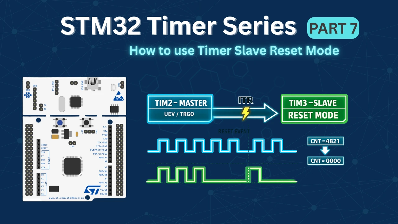
The diagram below shows how the master timer update event resets the slave timer counter through the internal trigger connection.
STM32CubeMX Configuration
Now that we understand how Slave Reset Mode works internally, let’s configure the timers using STM32CubeMX. In this section, we will set up one timer as the master to generate the update trigger event and configure the second timer as the slave in Reset Mode using the appropriate internal trigger (ITR) connection.
Clock Configuration
The image below shows the clock tree for this project.
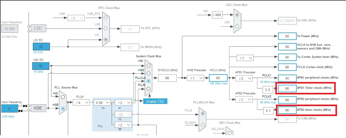
Here I have configured the external crystal, which is 8 MHz, to provide the clock, such that the system will run at 90 MHz. This is to make sure that both the APB timer clocks have the same speeds and so all the timers will wave the same base clock.
Master and Slave Timers’ Configuration
I am going to configure the TIM2 in the master mode and TIM2 the TIM3 will act as the slave timer.
Whenever the master counter (TIM2) overflows, it will generate an UEV signal which will reset the counter of the TIM3.
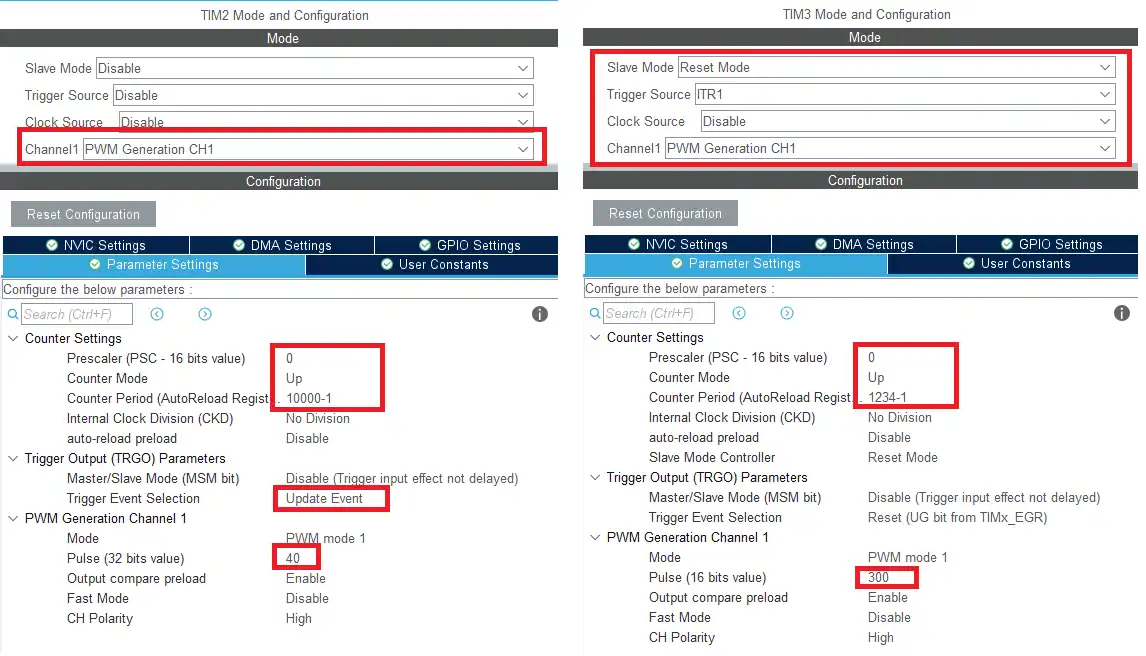
- Here I have enabled the PWM on channel 1 for both the timers so that we can see their output.
- Both the timers are clocked by the APB clock, so the base frequency is 90 MHz. This is further reduced by using the ARR.
- TIM2 will run at 90MHz/10000 = 9KHz with the duty cycle of 0.4%
- TIM3 will run at 90MHz/1234 = 73KHz with duty cycle of 24%
- TIM2 is the master timer, so the trigger event selection is set as Update Event (UEV). TIM2 will issue this UEV signal when the counter overflows.
- TIM3 is the slave to the TIM2 and is being used in the RESET Mode. The trigger source is ITR1.
Note:
Calculate the ARR and CCR values for the STM32F4 Timers using the STM32F4 PWM Tool:
https://controllerstech.com/tools/stm32f4-pwm-calculator/
Basically in the Slave Reset Mode, whenever the TIM3 receives the UEV signal from TIM2, the TIM3’s counter resets back to 0. We will see this happening in the working section.
STM32 HAL Code for Slave Reset Mode
The timer synchronization in Slave Reset Mode is handled mainly through the timer configuration structures created by HAL. Therefor, we do not need to write much in the code. Here I am only starting the PWM for both the timers, so we can see their behavior on the scope.
  /* USER CODE BEGIN 2 */

  HAL_TIM_PWM_Start(&htim2, TIM_CHANNEL_1);
  HAL_TIM_PWM_Start(&htim3, TIM_CHANNEL_1);

/* USER CODE END 2 */Result of the Timer Slave Reset Mode
The image below shows the PWM signals generated by both the timers.
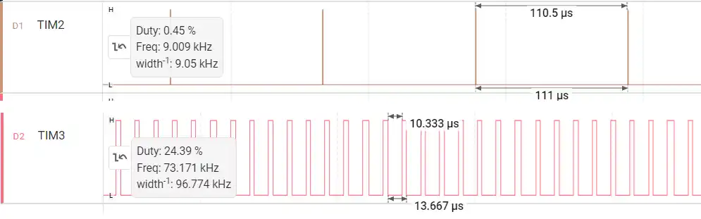
In the picture above you can see the TIM2 PWM signal have the frequency of 9KHz and the Duty of 0.4%. Similarly, the TIM3 PWM have the frequency of 73KHz and the Duty of 24%.
This is as per the setup we did for the Timers.
If we analyze the TIM3 PWM signal more closely, it can be seen that the signal remains HIGH for the period of 3.33us. This is always the case except at the point where the TIM2’s counter overflows. This is shown below.
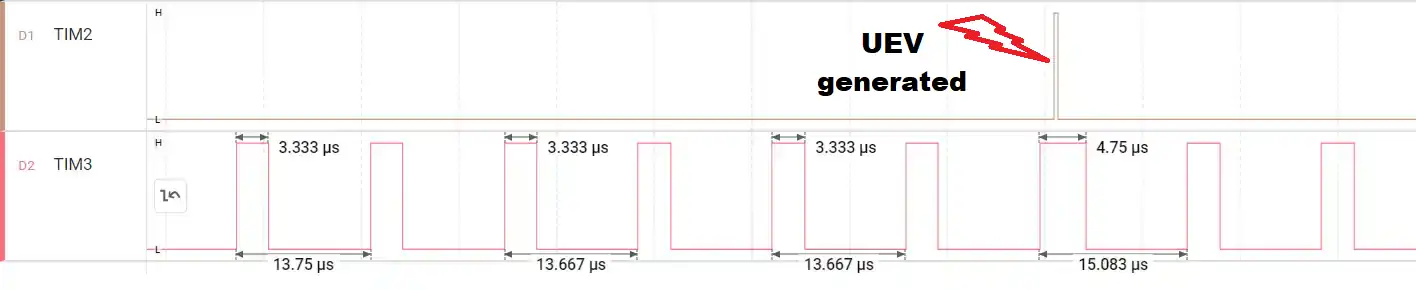
At the point where the TIM2’s counter overflows and generates the UEV, the TIM3’s signal remains high for 4.75us.
Let’s understand what exactly is happening at this point.
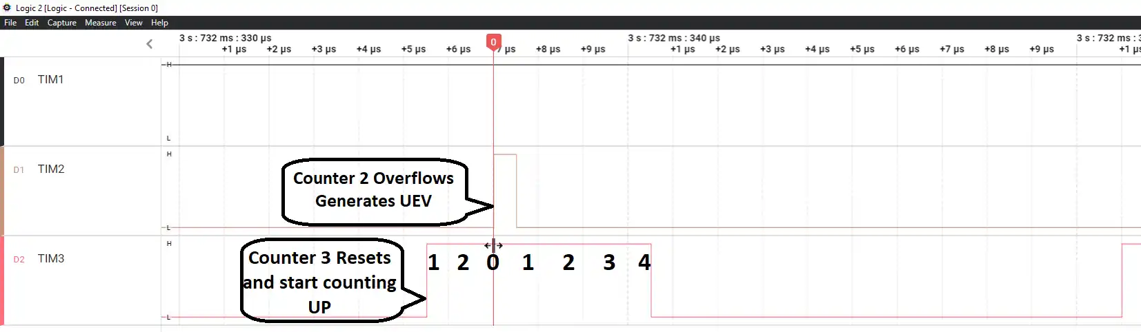
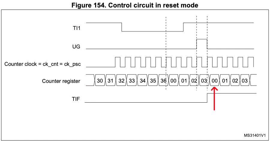
- Here you can see the TIM3 counter was counting UP from 0, and in between it received the trigger signal from the TIM2.
- At this point the counter resets back to 0 and again starting counting UP.
- That is why the signal remains HIGH for the additional time.
Note:
The above picture assumes the CCR(Pulse) value is set to 4, so the signal remains high till the counter reaches the value 4.
If we carefully observe the waveform on an oscilloscope and measure the time difference between the moment the Update Event (UEV) is generated by the master timer and the instant when the TIM3 output pulse transitions to LOW, we will notice that this duration is approximately equal to the configured pulse width (CCR value) of TIM3.
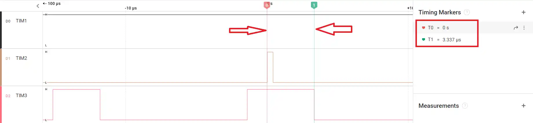
This happens because when the master issues the update event, the slave timer (TIM3) immediately resets its counter to zero. From that reset point onward, TIM3 starts counting again from 0 up to its compare value (CCR). The output remains HIGH until the counter reaches the CCR value, at which point it transitions to LOW. Therefore, the time between the reset trigger and the falling edge of the PWM signal directly represents the pulse width of TIM3.
In other words, the reset event defines a new timing reference point for the slave timer. Every time the master overflows, TIM3 restarts its counting cycle, and the HIGH duration of its PWM output begins from that reset instant. This is why the measured time difference aligns closely with the programmed pulse width.
Video Tutorial
STM32 Timer Synchronization – Slave Reset Mode Video Tutorial
This video explains how to configure STM32 Timer Synchronization in Slave Reset Mode, where the slave timer counter is reset on every master update event. You’ll learn how to set the master timer to generate TRGO on update, configure the slave timer in Reset Mode using the correct internal trigger (ITR), and observe how the counter restarts automatically. The step-by-step walkthrough covers CubeMX configuration, HAL setup, and oscilloscope verification to clearly demonstrate how reset-based synchronization works in hardware.
Watch the VideoConclusion
Slave Reset Mode provides a powerful way to tightly synchronize multiple timers in STM32. By configuring one timer as the master to generate an update trigger and setting the second timer in Reset Mode, the slave counter is forced to restart on every master overflow. This ensures precise alignment between timing cycles and makes the relationship between both timers deterministic and hardware-controlled.
Unlike Trigger Mode, where the slave simply starts counting when triggered, Reset Mode continuously realigns the slave timer with the master. This makes it especially useful in applications where exact timing relationships are critical, such as advanced PWM generation, waveform shaping, and coordinated timer-based control systems. By leveraging STM32’s internal trigger (ITR) connections, all of this synchronization happens internally without CPU overhead, resulting in efficient and reliable timing behavior.
Browse More STM32 Timer Tutorials
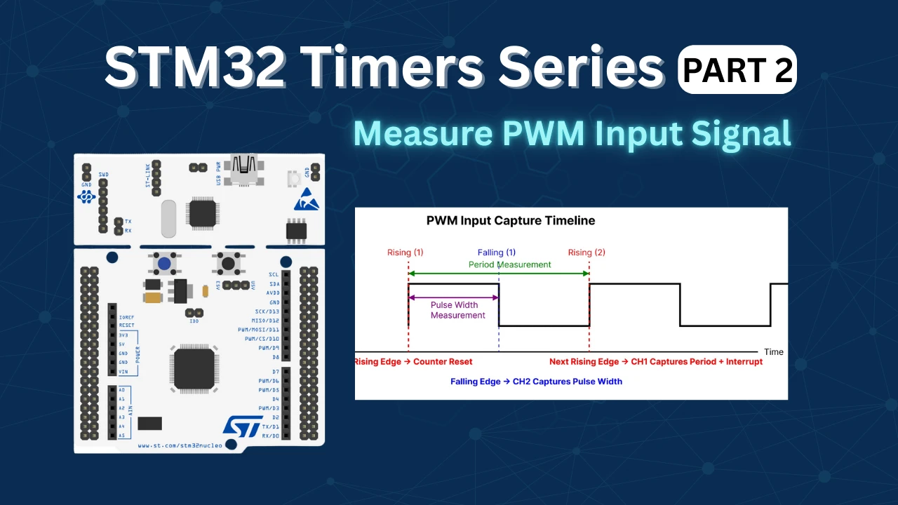
STM32 Timers (Part 2): How to Measure PWM Input Signal
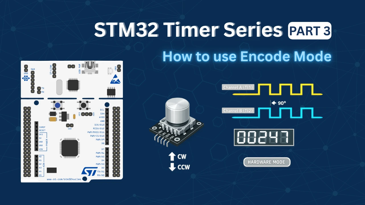
STM32 Timers (Part 3): How to use the Timer Encoder Mode
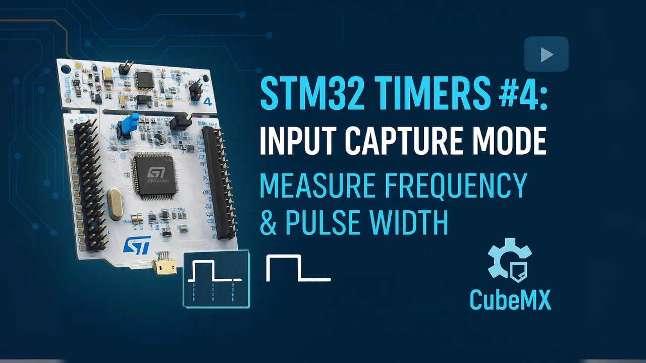
STM32 Input Capture: Measure Frequency & Pulse Width
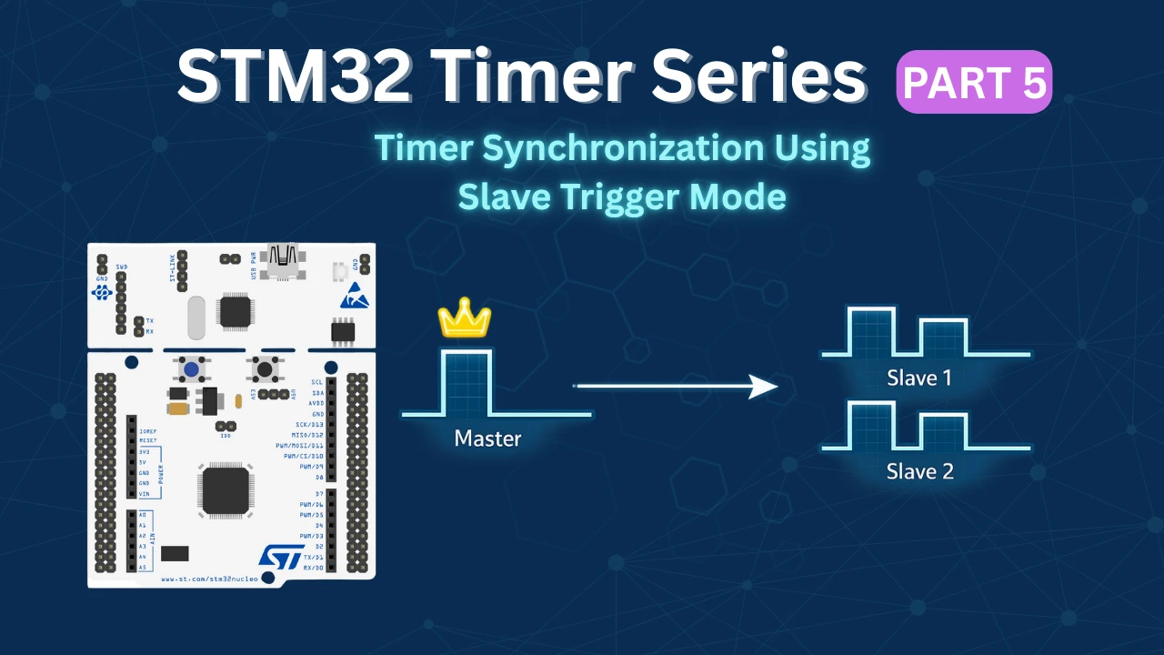
STM32 Timer Synchronization: Slave Trigger Mode with CubeMX & HAL
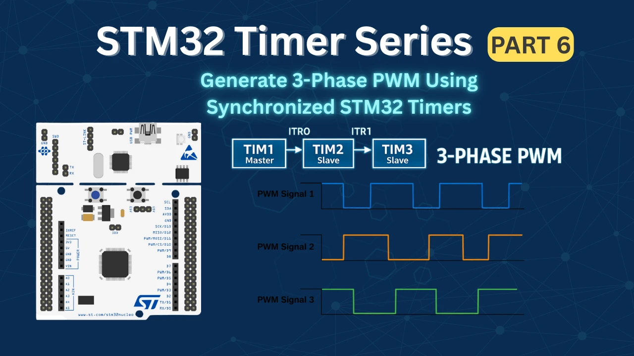
STM32 Timers (Part 6): Timer Synchronization for 3-Phase PWM Generation
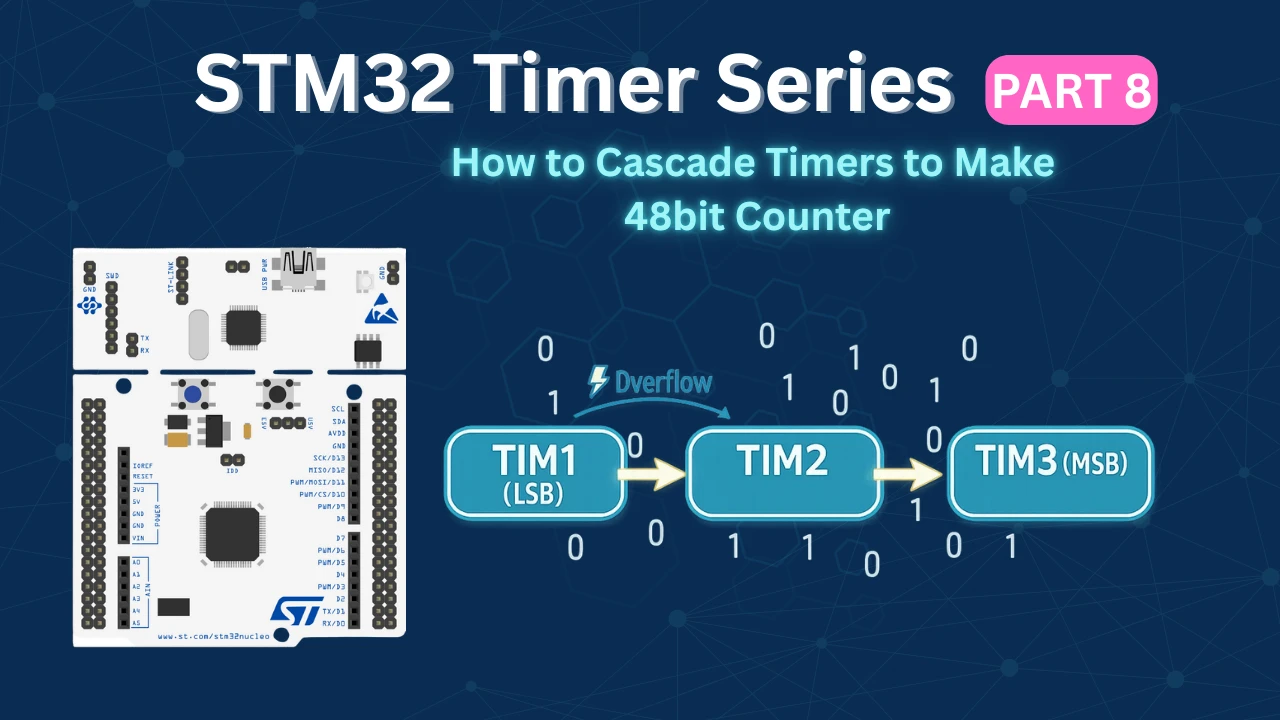
STM32 Timers (Part 8): How to Create a 48-Bit Counter by Cascading Timers
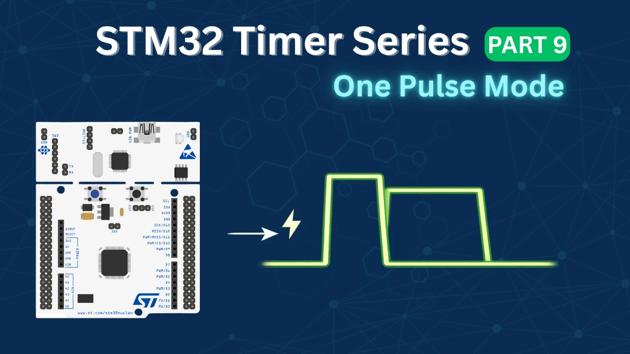
STM32 Timers (Part 9): One Pulse Mode (OPM) – Generate Precise Triggered Pulses with Delay and Width Control
STM32 Slave Reset Mode Project Download
STM32 Slave Reset Mode PWM FAQs


hello,
Thank you very much, Sir.