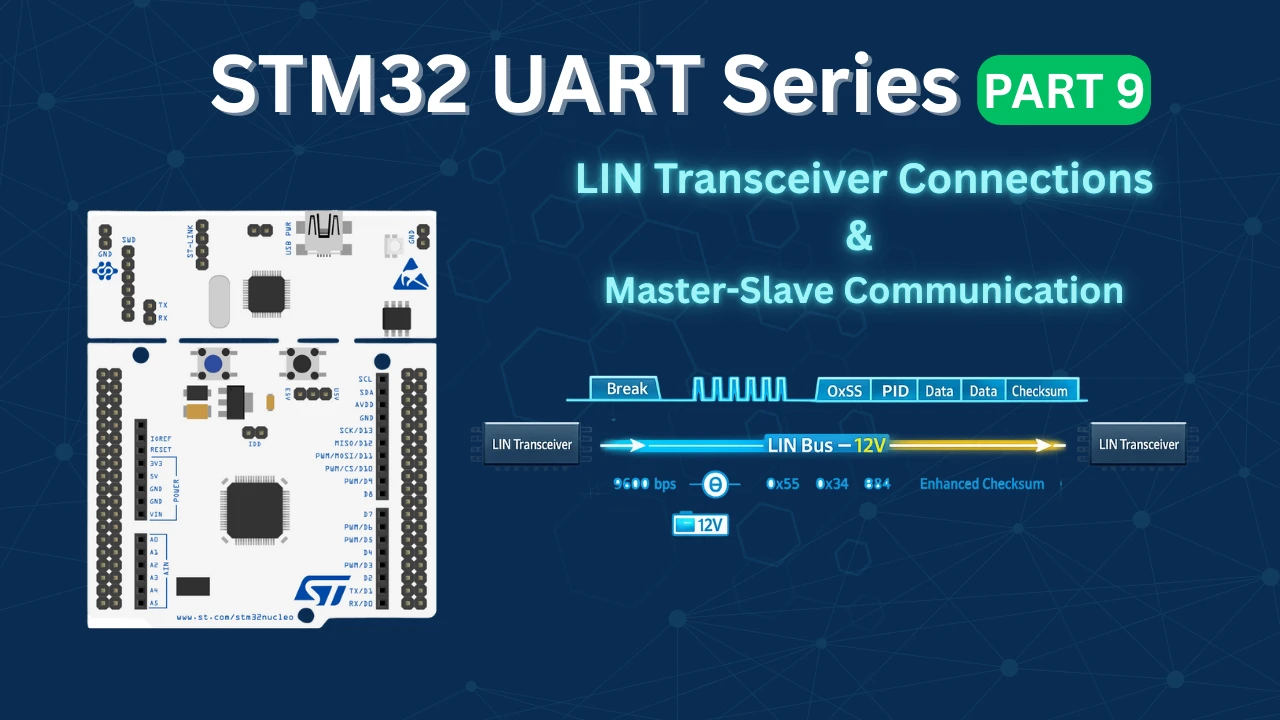
LIN Transceiver Connections & Master-Slave Communication
This is the 9th tutorial in the series on the UART peripheral of STM32 Microcontrollers. In this series we will cover different ways of transmitting and receiving data over the UART protocol. We will also see different UART modes available in the STM32 microcontrollers and how to use them.
In the previous tutorial, we generated a valid LIN 2.1 frame using STM32 configured as a LIN master. In this part, we will move beyond frame generation and establish real LIN communication between two STM32 boards using external LIN transceivers.
We will configure one STM32 as the master and another as the slave, connect both through LIN transceiver ICs, and build a complete LIN bus setup. The master will transmit LIN frames, and the slave will receive and validate them by checking the protected ID and checksum. By the end of this tutorial, you will have a fully working master–slave LIN communication system verified in real hardware.
MCP2004 – The LIN Transceiver
For this project, I am using Microchip’s MCP2004 as the LIN transceiver. There is no special technical reason for selecting this particular IC — it was simply easily available. You can also use the MCP2003, as it is very similar in functionality and pin configuration. Both devices are commonly used in LIN-based automotive applications and are well suited for interfacing a microcontroller UART with the LIN bus.
A LIN transceiver is required because the UART peripheral of the STM32 operates at standard logic voltage levels (3.3V or 5V), whereas the LIN bus operates at automotive voltage levels (typically 12V). The transceiver performs voltage level shifting, signal conditioning, and bus protection, making communication reliable and compliant with the LIN physical layer specification.
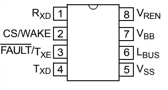
Below is a description of the important pins of the MCP2004 and how they are connected in our setup:
RXD (Receive Data Output)
RXD is an open-drain (OD) output pin. It provides the received LIN bus data to the microcontroller. Since it is open-drain, it requires a pull-up (usually internal or external, depending on configuration).
This pin must be connected to the RX pin of the STM32 UART, allowing the MCU to receive data coming from the LIN bus.
TXD (Transmit Data Input)
TXD is the transmit input pin of the transceiver and includes an internal pull-up resistor.
- When TXD is LOW, the LIN bus is driven to the dominant (LOW) state.
- When TXD is HIGH, the LIN bus goes to the recessive (HIGH) state.
This pin must be connected to the TX pin of the STM32 UART, so any data transmitted by the MCU is converted into proper LIN bus signaling.
CS (Chip Select)
The CS pin is used to enable or disable the transmitter section of the transceiver.
- Setting CS HIGH enables the transmitter.
- Setting CS LOW disables the transmitter.
In this tutorial, we will connect the CS pin to a GPIO pin of the STM32, allowing software control over when the node is allowed to transmit on the LIN bus.
FAULT/TXE
The FAULT/TXE pin is a bidirectional pin used for transmitter disable control and fault reporting. It can indicate error conditions related to the transmitter or allow additional shutdown control.
For simplicity, we will leave this pin unconnected, as fault monitoring is not required for this demonstration.
LBUS (LIN Bus)
LBUS is the bidirectional LIN bus pin of the transceiver. It is controlled internally based on the TXD input and bus conditions.
This pin will be connected to the LBUS pin of the other LIN transceiver, forming the actual LIN communication line between the master and slave nodes.
VBB (Battery Supply)
VBB is the battery positive supply pin, typically connected to a 12V automotive supply. This powers the LIN bus driver section of the transceiver.
We will connect this pin to the +12V supply.
VSS (Ground)
VSS is the ground reference pin of the transceiver. It must be connected to the ground of the 12V supply, and this ground must also be common with the STM32 ground to ensure proper communication.
VREN (Voltage Regulator Enable Output)
VREN is used to enable an external voltage regulator in automotive applications. Since we are powering the STM32 separately and not using this feature, we will leave this pin unconnected.
Wiring Connection between Master and Slave
Below is the image showing the connection between the MCUs and their respective transceivers.
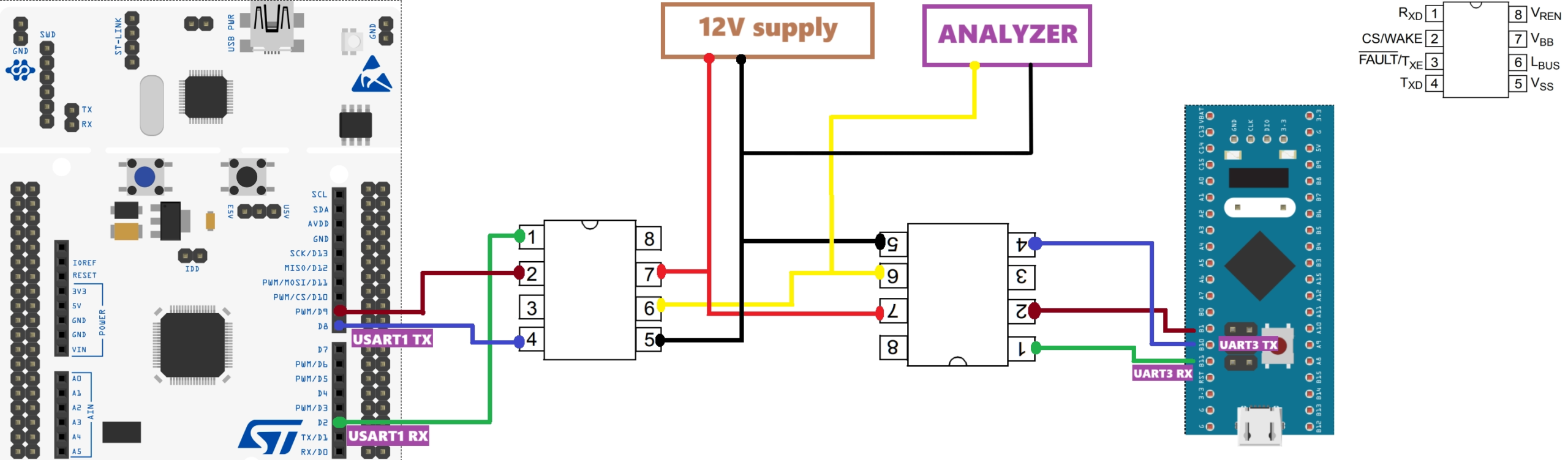
The UART TX pins are connected to the transceiver TX pins and the UART RX pins are connected to the transceiver RX pins. The pin 2 of the transceiver is the CS pin and it is connected to the respective GPIO on the MCU.
The Lin bus of the transceivers are connected together as it will transmit and receive the signal.
The transceivers are powered using 12V from the battery.
Configure STM32 as LIN Master
I am going to configure one STM32 as the master and another as the slave. Let’s tart with the CubeMX configuration first.
STM32 CubeMX Configuration
Below is the image showing the configuration of the UART in the Lin mode.
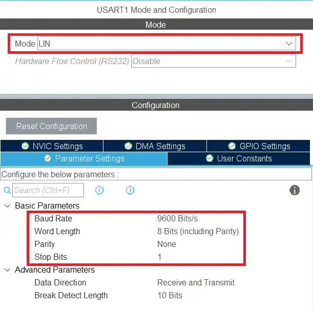
The USART1 is configured in the LIN mode. The LIN protocol supports the transfer up to the baud rate of 200 Kbps, but here I am using 9600 bps. The data size is set to 8 bits with no parity and 1 stop bit.
We also need to set a GPIO pin as the output. This will be used as the CS pin for the transceiver.
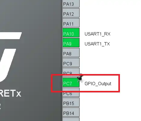
Here I am setting the pin PC7 as the output pin.
STM32 HAL Code for LIN Master
I have already explained the master code in the previous tutorial. Although I have made some changes in the data we are going to send and it is explained below.
Below is the code in the main function.
int indx = 0;

int main ()
{
  ...
  HAL_GPIO_WritePin(GPIOC, GPIO_PIN_7, 1);  // Pull the cs pin HIGH to enable transmitter
  while (1)
  {

	  TxData[0] = 0x55;  // sync field
	  TxData[1] = pid_Calc(0x34);
	  for (int i=0; i<8; i++)
	  {
		  TxData[i+2] = indx++;
                  if (indx>255) indx = 0;
	  }
	  TxData[10] = checksum_Calc(TxData[1], TxData+2, 8);   //lin 2.1 includes PID, for line v1 use PID =0

	  HAL_LIN_SendBreak(&huart1);
	  HAL_UART_Transmit(&huart1, TxData, 11, 1000);
	  HAL_Delay(1000);
  }
}Since the master will be transmitting the data continuously, we would want to keep the transmitter mode enabled. This is why the CS pin is set to HIGH.
We will send the TxData buffer via the UART, so we need to prepare it first.
- First store the sync bytes (0x55) to the buffer.
- The next element will contain the PID. Here I am using the ID 0x34, which will be then converted to the PID.
- Then copy the data bytes to the buffer. I am storing 8 data bytes with the values starting from 0 to 7. The data bytes are just the values of the indx variable, which will keep incrementing.
- The last element of the buffer will contain the checksum.
- I am using the Lin version 2.1, so the PID must be included in the checksum.
- For the lin version 1.x, the PID is not needed and hence you can just pass the value 0 for the PID.
After preparing the TxData buffer, we will send it via the UART. The function HAL_LIN_SendBreak is used to send the break field. After sending the break field, we will send the TxData buffer.
Configure STM32 as LIN Slave
I am going to use the STM32F103C8T6 as the slave MCU. Below is the configuration of the slave MCU.
STM32CubeMX Configuration
Below is the image showing the cubeMX configuration of the slave MCU.
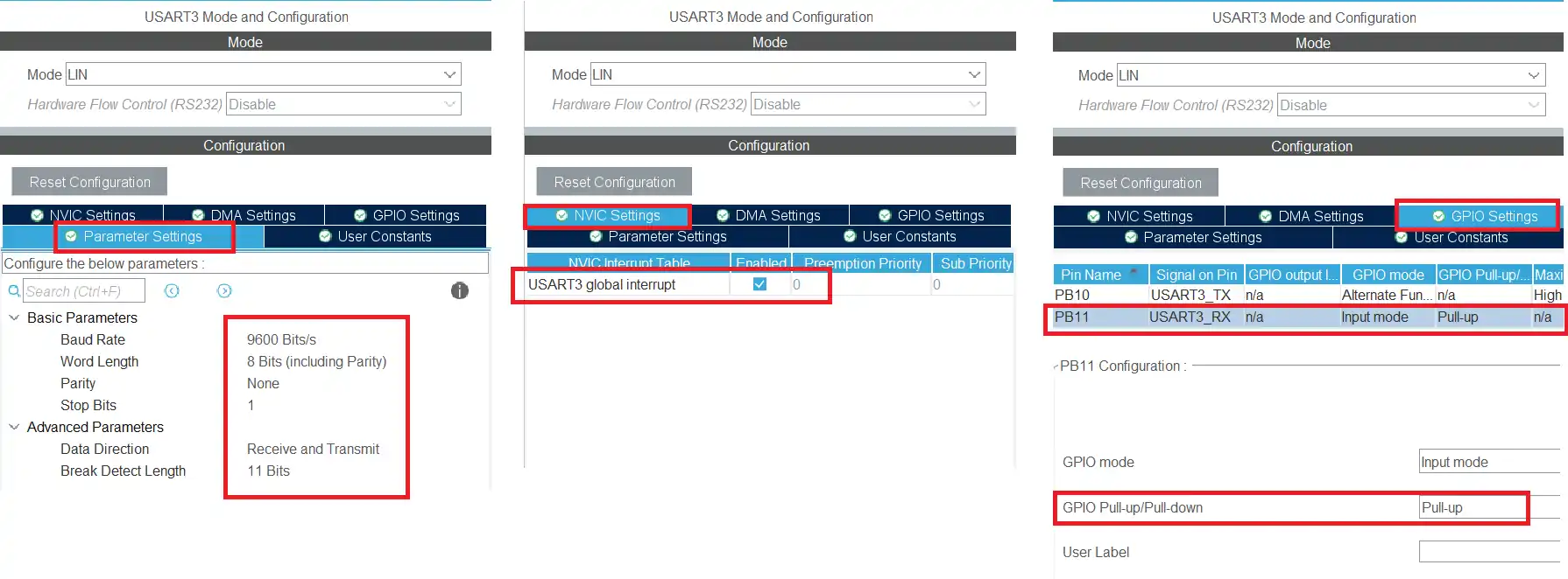
I am using the USART3 on the STM32F103C8T6. The USART is configured in the Lin Mode with the baud rate of 9600 bps, 8 data bits with 1 stop bit and no parity. This is basically the same configuration as we did in the master MCU.
I have also enabled the Global interrupt for the USART3 as I am going to receive the data in the interrupt mode.
Also make sure to enable the pull up for the RX pin in the GPIO setting. This is necessary or else the data will not be received. If your MCu does not support the internal pullup, connect an external pull up on this pin.
We also need to set a GPIO pin as the output. This will be used as the CS pin for the transceiver.
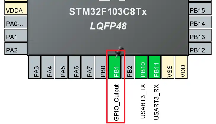
Here I am using the pin PB1 as the CS pin for the Transceiver IC.
STM32 HAL Code for LIN Master
We will start with receiving the data via the UART in the interrupt mode.
HAL_UARTEx_ReceiveToIdle_IT(&huart3, RxData, 20);Here I am using the function receive to idle in the interrupt mode. So when all the 20 bytes has been received, or an idle line is detected before that, an interrupt will trigger and the RX Event Callback will be called.
We will process the received data inside this callback. Below is the image showing the data received by the slave in a single Lin frame.
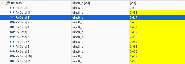
The received bytes contains the following:
- 1 byte of the break field (0x00).
- 1 byte of the Sync field (0x55).
- 1 byte of the protected ID.
- 1 – 8 bytes of actual data.
- 1 byte of the checksum.
Basically other than the actual data bytes, we have 4 extra bytes containing other information. Since the master can send any number of actual data bytes between 1 to 8 bytes, we must have some means in the slave device to figure out how many actual data bytes were sent by the master.
The variable numDataBytes will be used to track the actual number of data bytes received. The Size parameter of the callback contains the total bytes received and we have 4 additional bytes other than the data bytes. To extract the actual number of data bytes, we can simply use numDataBytes = Size – 4.
void HAL_UARTEx_RxEventCallback(UART_HandleTypeDef *huart, uint16_t Size)
{
numDataBytes = Size - 4;We can check the validity of the received data by calculating the checksum. The actual data starts from the offset of 3, and the total number of data bytes has already been calculated.
We will verify this checksum with the received checksum. If it is same, that means the received data is valid and we can process it. Here we will set the variable isDataValid to 1 so that we can later process the data in the while loop.
	uint8_t checksum = checksum_Calc(RxData[2], RxData+3, numDataBytes);
	if (checksum != RxData[Size-1])
	{
		isDataValid = 0;
		// call error handler
	}
else isDataValid = 1;We can also extract the actual ID from the protected ID. We know that the protected ID is made up of 6 bits of the actual ID and the 2 parity bits (P0 & P1). So to extract the actual ID from the PID, we can simply extract the first 6 bits from it.
ID = RxData[2]&0x3F;Finally call the receive to idle function again, so that we have the continuous reception of data.
	HAL_UARTEx_ReceiveToIdle_IT(&huart3, RxData, 20);
}We will process the data in the while loop.
  while (1)
  {
	  if (isDataValid == 1)
	  {
		  for (int i=0; i<numDataBytes; i++)
		  {
			  Data[i] = RxData[i+3];
		  }
		  isDataValid = 0;
	  }
}Here we will check if the isDataValid variable is set to 1. If it is, then we will copy the received data from the RX buffer to the Data buffer. We can process this data buffer in any way we want.
Also set the isDataValid variable to 0, so that this loop does not run again.
Result of LIN protocol communication
Below the images shows the data received by the slave MCU and the actual data extracted from the received data.
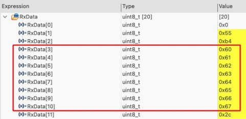
The slave received a total of 12 bytes of data. The received data contains the following:
- The break field 0x00.
- The sync field 0x55.
- The PID 0xB4.
- 8 Data bytes.
- The checksum byte.
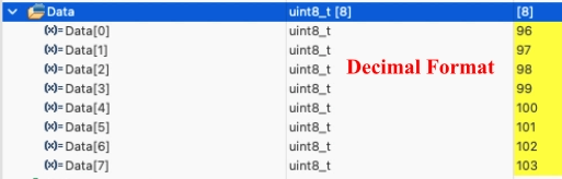
The Data buffer contains the 8 data bytes extracted from the RX buffer.
Video Tutorial
STM32 LIN Protocol – Master Slave Communication (Part 2)
This video demonstrates how to establish real LIN communication between two STM32 boards using MCP2004 LIN transceivers. It covers hardware connections, LIN bus setup, master frame transmission, slave reception using interrupts, checksum verification, and complete master–slave communication over the 12V LIN bus.
Watch the VideoConclusion
In this tutorial, we successfully established LIN communication between two STM32 boards using external LIN transceivers. The master node generated and transmitted a valid LIN frame, while the slave node received the frame, extracted the protected ID, and verified the checksum to ensure data integrity. By integrating the MCP2004 transceiver, we were able to interface the STM32 UART with the 12V LIN bus and create a proper physical layer connection.
With this setup, we now have a complete and functional LIN master–slave system operating in real hardware. This provides a strong foundation for building more advanced LIN-based applications such as automotive control modules or distributed embedded systems. In the next part, we can further enhance the implementation by adding structured data handling, multiple frame IDs, or diagnostic communication.
Browse More STM32 UART Tutorials
STM32 UART Part 3 – Receive Data in Blocking & Interrupt mode
STM32 UART DMA Receive: Normal & Circular Mode (HAL)
STM32 UART Idle Line: Receive Data via Interrupt & DMA
STM32 UART Part 6 – Half-Duplex Communication (Single-Wire Mode)
STM32 UART Part 7 – How to use one-Wire Protocol
STM32 UART Part 8 – LIN Communication Tutorial
STM32 UART PART 10 – Lin Protocol PART 3
STM32 UART LIN Project Download
STM32 UART LIN FAQs


I’m using TLIN2029EVM for the LIN Transceiver. The microcontroller which I’m using is STM32F072RB both the sides. But I’m not receiving the data. Can you please help me with that