Home ▸ STM32 Tutorials ▸
Updated On: March 23, 2026
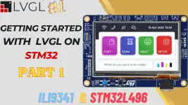
Integrate Touch interface on LVGL
This is the 2nd tutorial in the series covering LVGL on STM32. In today’s tutorial we will cover how to integrate the input driver (Touchpad in this case) to the LVGL.
You should have the drivers for your respective input device, as I will only show how to connect it to the LVGL input drivers. I am using the ILI9341 based SPI display which has the touchpad XPT2046.
VIDEO TUTORIAL
You can check the video to see the complete explanation and working of this project.
Connection & cubeMX Config
In the previous tutorial I showed the connection to the LCD, but it was such that we only get the output on the display. Now I have also connected the pins required by the touch interface to the controller. Below is the picture showing the connection.
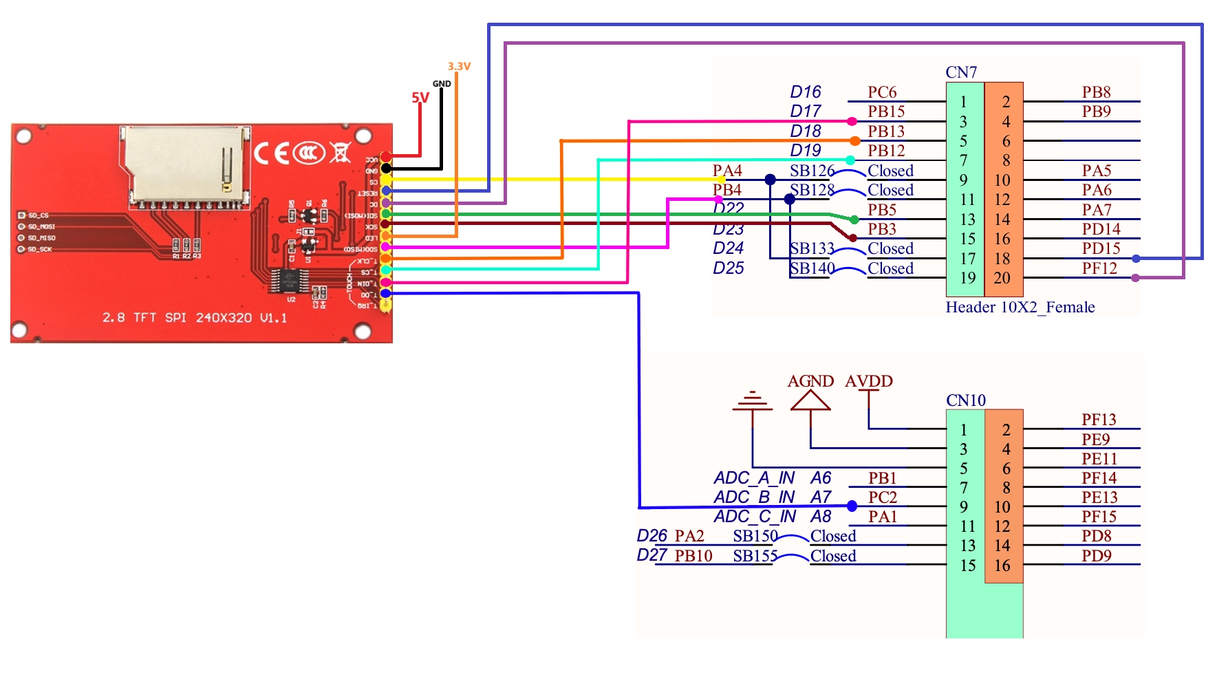
You can see the touch block is also connected to the controller now. I left the Interrupt (T_IRQ) pin unconnected for now. This is because the input interface LVGL can work without the interrupt, so I am not connecting that pin.
The touch interface also uses SPI, so we need to enable another SPI to connect the touch interface. Below is the picture showing the cubeMX configuration.
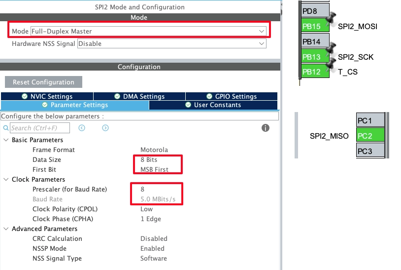
I have enabled the SPI2 in the full duplex mode. The data size is 8 bits and the baud rate is kept around 5Mbits/s.
Connect Input drivers to LVGL
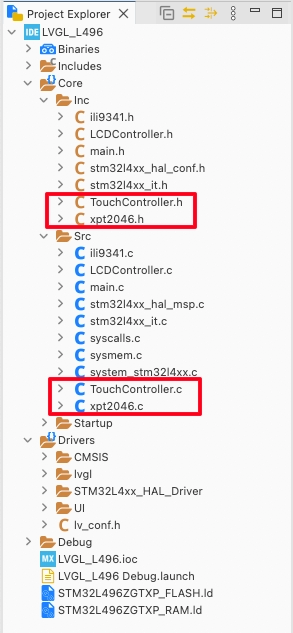
First copy the touch drivers to the project directory (src and inc folders). The create a new source file, TouchControler.c and a header file, TouchController.h. These are the files where we will write the code to connect the touch drivers to the LVGL input drivers.
The LVGL provides the template for the Input device. The template can be found at https://github.com/lvgl/lvgl/blob/release/v8.3/examples/porting/lv_port_indev_template.c. We can simply modify this template as per our need and availability of the MCU and the Display.
The lv_port_indev_init function is used to initialize the input driver.
void lv_port_indev_init(void)
{
    static lv_indev_drv_t indev_drv;

touchpad_init();Inside this function we will first define the input device driver. Then touchpad_init() function initializes the touchpad. This is where we will initialize our touch driver. This is shown below.
/*Initialize your touchpad*/
static void touchpad_init(void)
{
	XPT2046_Init();
}I have the XPT2046 touch interface, so I am initializing it inside the touchpad_init() function.
Then we register the input device.
	/*Register a touchpad input device*/
	lv_indev_drv_init(&indev_drv);
	indev_drv.type = LV_INDEV_TYPE_POINTER;
	indev_drv.read_cb = touchpad_read;
	indev_touchpad = lv_indev_drv_register(&indev_drv);
}- Here first we will initialize the input driver.
- The driver type is set to pointer, since we are using a touchpad.
- The read callback is set to touchpad_read, this will be called by LVGL at a regular interval to read the touch input.
- Finally register the input device driver.
The touchpad read function shown below.
static void touchpad_read(lv_indev_drv_t * indev_drv, lv_indev_data_t * data)
{
    static lv_coord_t last_x = 0;
    static lv_coord_t last_y = 0;

    /*Save the pressed coordinates and the state*/
    if(touchpad_is_pressed())
    {
//        touchpad_get_xy(last_x, last_y);
    	last_x = get_xy.x;
    	last_y = get_xy.y;
        data->state = LV_INDEV_STATE_PR;
    }
    else {
        data->state = LV_INDEV_STATE_REL;
    }

    /*Set the last pressed coordinates*/
    data->point.x = last_x;
    data->point.y = last_y;
}- Here we will first check if the touch is pressed and valid, using the function touchpad_is_read.
- If the touch is valid, then save the touch points in the variable last_x and last_y.
- The get_xy is the structure that stores the touchpoints when the function touchpad_is_read is called.
- At last we store the touch points inside the data structure.
This function is provided in the template itself. The only change I made is replace the touchpad_get_xy function, which is used to read the touch points, to directly providing the touch points using the structure get_xy.
The function touchpad_is_pressed is used to validate the touch. This is the main part of the input driver, where you need to write the code according to your touch driver.
Below is the code for the XPT2046 on the ILI9341.
static bool touchpad_is_pressed(void)
{
	/*Your code comes here*/
	static uint16_t prevx = GUI_WIDTH;
	static uint16_t prevy = GUI_HEIGHT;
	uint16_t intx, inty;
	XPT2046_Update(&intx, &inty);
	if (XPT2046_IsReasonable(intx, inty))
	{
		ConvXPTtoILI(&intx, &inty);
		if (intx != prevx || inty != prevy)
		{
			prevx = intx;
			prevy = inty;
			get_xy.x = (lv_coord_t )intx;
			get_xy.y = (lv_coord_t )inty;
			return true;
		}
	}
	return false;
}Initialise the Driver in the main file
Now we will add and initialise the touch driver in the main file.
#include "TouchController.h"
...
int main(void)
{
  ...
  lv_init();
  lv_port_disp_init();
  lv_port_indev_init();
  while (1)
  {
	  lv_timer_handler();
	  HAL_Delay(5);
  }
}Include the TouchController header file in side the main file. The after initialising the display driver, initialise the input device driver by calling lv_port_indev_init().
To test the touch driver, I am going to build the UI with a button on the screen. We will use the Squareline Studio to build our UI.
Create Project using Squareline Studio
Open the studio, and create a new project.
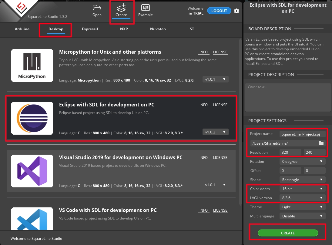
We will first generate the project for the Desktop environment, and then add it to the STM32 project.
- The Screen resolution is set to 320x240px
- Color depth is 16 bit.
- The LVGL version is 8.3.6, this should be same as what we download in the first tutorial.
- Click create to create the project.
Below is the UI design.
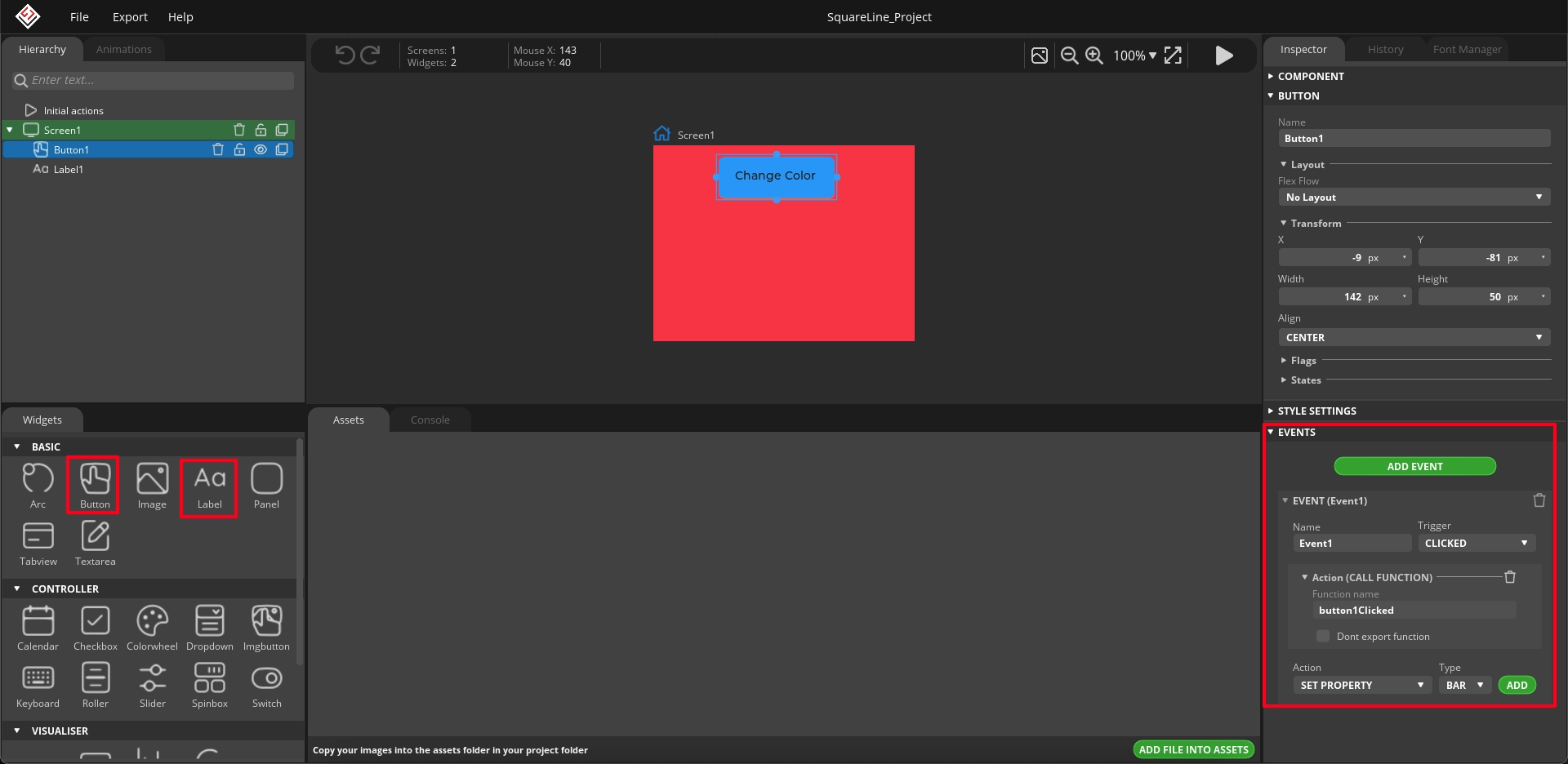
I have changed the background color to RED. The added a button and label on top of the button.
I have also added an event for the button. The event will be triggered when the button is clicked, which will eventually call a function, button1Clicked. We will write the code inside this function later in the IDE.
After the design is complete, save the project and then open the project setting to update few things.
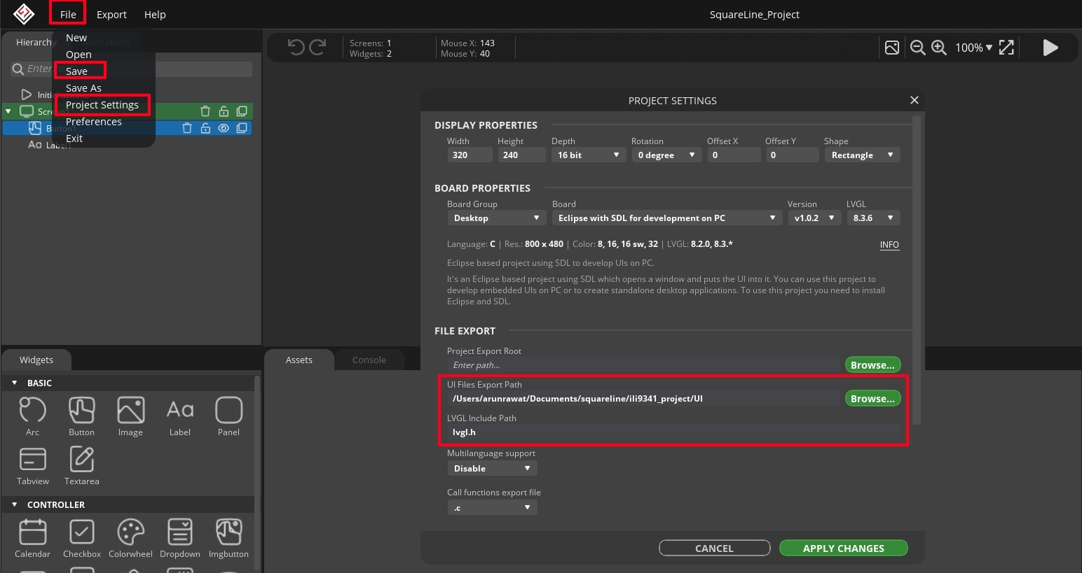
Here I have added the path for the UI file export. Also update the LVGL include path as shown in the image above.
After saving the project settings, we will export the UI files.
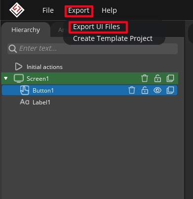
Click on Export, and then click Export UI Files. This will export the UI files in the path we set earlier. Below is the image showing the project folder.
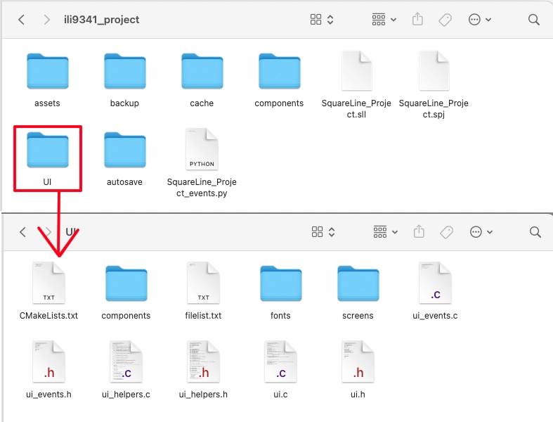
As you can see we have the UI files inside the project folder. This UI folder contains the files required by the LVGL to recreate the design on the display.
Add UI to the STM32 Project
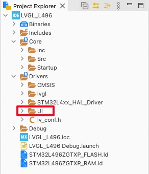
Copy the UI folder we just exported to the STM32 Project -> Drivers. Once you refresh the project in the IDE, the folder should be visible.
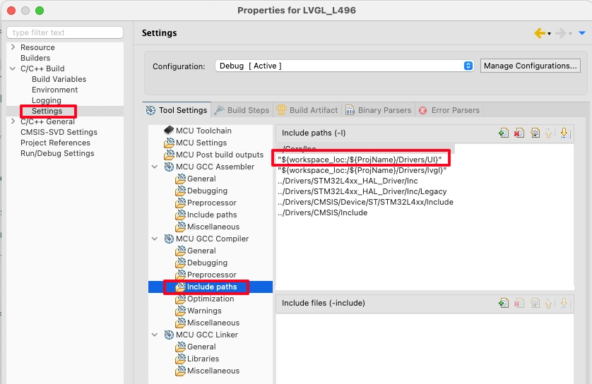
Right click on the project and open Properties.
open the c/c++ Build -> Settings -> MCU GCC Compiler -> Include Paths. Here click the add button to include the UI path to the project. This is same as how we added the LVGL to the path in the previous tutorial.
Now we will initialise the UI in the main file.
#include "ui.h"
...
int main(void)
{
  ...
  lv_init();
  lv_port_disp_init();
  lv_port_indev_init();
  ui_init();
  while (1)
  {
	  lv_timer_handler();
	  HAL_Delay(5);
  }
}Include the ui header file inside the main file. Then after initialising the LVGL display and input drivers, initialise the ui by calling ui_init().
While designing the UI, we created an event for the button clicked. When the button is clicked, the function button1Clicked will be called. This function is defined inside the UI->ui_event.c file. We will write some code which will execute on clicking the button.
int indx = 0;

void button1Clicked(lv_event_t * e)
{
	indx++;

	if (indx == 1)
	{
		lv_obj_set_style_bg_color(lv_scr_act(), lv_color_hex(0x003a57), LV_PART_MAIN);
	}

	else if (indx == 2)
	{
		lv_obj_set_style_bg_color(lv_scr_act(), lv_color_hex(0x00FF00), LV_PART_MAIN);
	}

	else if (indx == 3)
	{
		lv_obj_set_style_bg_color(lv_scr_act(), lv_color_hex(0xFF0000), LV_PART_MAIN);
	}

	else if (indx == 4)
	{
		lv_obj_set_style_bg_color(lv_scr_act(), lv_color_hex(0x123456), LV_PART_MAIN);
	}

	else if (indx == 5)
	{
		lv_obj_set_style_bg_color(lv_scr_act(), lv_color_hex(0x0000ff), LV_PART_MAIN);
		indx = 0;
	}
}
Here I am defining the variable indx, which will increment each time we click the button. For different values of this indx variable, I am setting the screen to have different background color.
Result
Below is the gif showing the display.

As you can see each time we click the button, the background color changes on the screen.
STM32 LVGL Tutorial Series
LVGL on Riverdi STM32-H7 Display
LVGL on STM32 || PART 4
LVGL ON STM32 || PART5
LVGL on STM32 || PART 6
LVGL on STM32 || PART7 || Load LVGL from Ext Flash
STM32 GC9A01 Round Display: SPI & LVGL Integration Guide
STM32 Analog Clock on GC9A01 — LVGL, SquareLine Studio & RTC


Dear Sir,
Following your instructions I have created projects described in Part 2, Part 4 and Part 5.
All projects I have successfully built and managed to upload to MCU (Nucleo L496ZG-P).
TFT is ILI9431 with 2.8 inch screen.
I have faced a problem – display doesn’t react for touch although graphic part works smoothly.
The mistake in connection is rather excluded. ALL touch pins are giving signal what I have checked in simple Led togglin application.
Have you any hint for me ?
ALL touch pins are giving signal what I have checked in simple Led toggling application.
To clarify that what I have written above – in another project I was sending signal to LED from MCU pins CS, RESET, DC, etc.
Hi,
Does stm32f767 development board supports lvgl?
Yes